Calibration and Linearity issues for an Adaptive Antenna System
George V. Tsoulos and Mark A. Beach Centre for Communications Research University of Bristol, Merchant and Venturers Building, Room 2.19, Woodland Road, Bristol, BS8 lUB, UK tel: +44 (1 17) 954 5203, fax: +44 (117) 954 5206, e-mail:
[email protected]
Abstract Adaptive Antennas are among the favourite techniques to help the current systems evolve towards third generation mobile communication systems. However, among the major concerns for adaptive antenna systems are the calibration process and the non-linearity effects of the RF-IF chains upon the pegormance of the beamforming network. This contribution investigates these issues based on experimental results pnoduced with the adaptive antenna testbed that was developed under the RACE TSUNAMI project. Results highlight the sensitivity of the system on both the linearisation and the calibration processes emplayed.
I. Introduction Both the UMTS and the FPLMTS systems that have been proposed to take the communications into the next information century introduce severe restrictions for any mobile communications system [l], and thus motivate the need for new technologies, e.g. the deployment of smaller radio cells, combination of different cell types in mixed cell architectures, advanced signal processing, fixed sector or multibeam and adaptive (or smart) antennas. In particular for the case of adaptive antennas, with efficient use of spatial processing at a cell site, optimum receive and transmit beams can be formed and hence the spatial dimension can be exploited in terms of another multiple access technique on top of these that the systems already employs (time-frequency-code). This approach is usually referred to as SDMA (Space Division Multiple Access), and enables multiple users within the same cell to be accommodated on the same frequency and time slot by exploiting the spatial filtering properties offered by the adaptive antenna.
0-7803-3659-3/97 $10.000 1 997 IEEE
Considerable research has been undertaken from researchers around the world [2-81, in order to fully assess the benefits of this technology to current and future mobile networks. In order to further research in this promising area the Commission of the European Community funded a two year (19941995) project with the code name TSUNAMI'. The program comprised of a combination of analysis, computer simulation, propagation measurements and technology/commercial analysis, in order to achieve the objective which was to identify, evaluate and develop adaptive antenna technologies applicable to third generation mobile systems. In the following, experimental results produced with the testbed developed under the RACE TSUNAMI project are presented in order to investigate the sensitivity of the adaptive antenna system on two of the most critical factors affecting its performance: the calibration process and the linearity of the transceiver chains.
11. Field Trial System One main objective of the TSUNAMI project was to setup a field trial system based on the DECT system, which supports adaptive beamforming for both receive and transmit directions. The system has 8 antenna elements with 8 independent upconverters and down-converters. The complex baseband signals are sampled and digitized as input to a digital beamforming network with two independent outputs. Each output corresponds to a beamformer and signal processing unit for weight computation and is demodulated and decoded by a separate DECT subsystem. The beamforming for transmit direction is performed vice versa. A calibration system with a generator, a set of 8 Technology in Smart antennas for UNiversal Advanced Mobile Infrastructure.
1597
couplers and switches and a special receiver for transmit direction is available for measurement of the actual gain and phase of each receiver and transmitter path. The achieved calibration data are used to normalize the different channels for proper beamformer operation. Two independent DSPs are running the beamforming algorithms for the different inputs and outputs to the DECT subsystems, enabling the trial system to establish two links within the same timeslot and frequency of DECT with independent antenna characteristics. The beamforming system has a 16 Mbytes DRAM for data logging during the trials. A controlling PC with VME-bus interface is used to load the beamforming algorithms, to start the measurements and to read the stored data out of the system. The DECT subsystem contains two digital basestation controllers assembled together with burst mode unit and speech codec. Both controllers are synchronized together as master and slave and are running in synchronism with the digital beamformers. Each basestation is controlled by the PC via a serial line for configuration, connection setup and data logging. The DECT system has one standard transmitter module, which can be used for reference connections during the trials. In order to get a quantitative performance measure, the instantaneous BER is computed. This is done after demodulation, where the signal is compared with a known reference sequence in order to calculate the errors that have occurred. The reference sequence is a 320 bit sequence in the B-field of the data field of the DECT burst.
For the SDMA tests the MUSIC algorithm is used as the spatial reference algorithm. Each iteration of the adaptive algorithm consists of three steps: 1. Estimate the number of signals and directions of arrival using the MUSIC algorithm. 2. Apply the DOAs to the tracking algorithm. 3. Synthesise beams for the users. To obtain acceptable results, it was necessary to improve the quality of the system in order to have very accurate and stable calibration values. Otherwise no clear separation of the mobiles is possible, because the computed and realized beams differ too much. To calibrate the receivers an external signal generator is used to produce a carrier tone which is split in eight ways and injected into the receiver channels with couplers behind each antenna element. Calibration is performed by dividing the digitised signal of each channel by the input signal. The absolute values of amplitude and phase for each channel do not need to be known as these have no effect on the beam pattern, it is only the amplitude and phase differences between the channels which have an effect. Since the receiver contains AGC, calibration must be repeated for each gain setting, because although the gain across the array is constant, the element mismatch varies at different gain settings. The gain is adjustable over 40dB range in 3dB steps, so at least 13 calibrations must be performed at each DECT carrier frequency.
RFlm.-im
Antenna
Tx I Rx
Dnwn-/up conversion
Dual Dirital
TI Transmitter Calibrator Figure 2: Transmitter Calibration Outline.
Cnnunl Cnmputer Embedded VMEbus PC
Figure 1 : RACE TSUNAMI test bed architecture
Calibration of the transmitters is more difficult and figure 2 shows a basic outline of the transmitter calibration scheme. The calibrator takes a sample from each transmission channel in turn and uses it
PI.
1598
Day I
to generate an error signal with which to compensate for the mismatches in the transmitters.
14OC
17'C
22'C
Day 2
24OC
27OC
- - .......................
Day 3
~ 2 4 ~ -u0c C
0
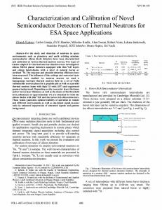
111. Experimental Results As it is shown in figure 3, measurements were taken for a temperature range from 14OC to 27OC. Also, for a room temperature of 24OC the tests were repeated during different days. Day 1 14%
17OC
__ __
22OC
Day2 24%
27%
............
Day3
4 4 % x24'C
0
0
elements
(4
2
1
3
4
5 elements
1
5
Day 1
14OC
I7'C
22%
- - ....................
27'C
8
It can be seen that the amplitude mismatch can be as high as k 1.5dB, or even higher (transmit path), while the phase varies over a much broader range of almost k 180'. It is worth noticing that even with the same room temperature the amplitude and phase mismatches can be very different from day to day. After calibration, the amplitude mismatch can be limited to k0.04dB and the phase mismatch to
Day3
Day?.
24%
7
Figure 3: Rx calibration as a function of temperature: a) amplitude mismatch before calibration, b) amplitude mismatch after calibration, c) phase mismatch before calibration, d) phase mismatch after calibration.
r24'C
rU0C 0
0
k 0.4'. acquir2 : CalibrationSnapshot dah (element 6)
1
2
3
4 5 elements
6
7
8
(b) Day:! 14Oc
17%
22k
24Oc
........................
Day3
nnc ..mac
-2aOc
-128
-100
-50
0
50
100
I 127
i (LSBs)
Figure 4: Eye diagram before and after calibration and with old calibration factors for the sixth antenna element. 2
3
4 5 elements
6
7
8
Figure 4 shows the eye diagram produced with results taken from the calibration experiments, for the sixth antenna element. No data is received and only the calibration process is considered. The
1599
noisy offset ellipse is the un-calibrated output, the noisy inner circle is the calibrated output but with calibration factors calculated in a previous day, and the outer centered to zero circle is the calibrated output. Obviously with the old calibration factors the ellipse is corrected and centered to zero but it still remains noisy. After the new calibration the system is almost perfect. The only problem that was noticed during the experiments was that although all the circles should have the same radius, there are small deviations. This is because the array elements can introduce small imbalances for which the calibration loop employed in this testbed can do nothing.
IV. Linearity requirements Because the weights for the beamformer are calculated at digital base-band, any distortion in the up and down conversion chains will alter the produced radiation pattern. In [lo] it was shown that with a non-linear system the sidelobe levels increase and the nulls shift and are increased. These effects not only limit the resolution of SDMA but also increase the amount of interference and limit the ability for interference cancellation. 8
,
,
,!!',I,',
I
I
I
I
,'
I
I
I
, ,
I
I
I
I
I
I
- 1 2 " " " " " " " " " " " " " " ' -70 -60 -50 -40 -30 -20 -10 0 10 20 30 40 50 60 70 Angle (degrees)
Figure 5 : Difference of the measured radiation patterns with and without linear power amplifiers. In figure 5 results from measurements for the radiation pattern with and without linear power amplifiers (a feedforward technique was employed here [9]), along with the ideal pattern, are shown. The scenario assumes that the desired user is at -30' and that there are interfering users at -3', -32', -37', -43', -45', and -50'. It can be seen that without linear power amplifiers the sidelobe level is generally increased and in particular for the nulls,
there is a decrease which ranges from 5dB to 12dB (figure 5).
V. Conclusions An experimental investigation of the sensitivity of an adaptive antenna system on the calibration and the non-linearity of the RF-IFchains was presented here. Results highlighted the susceptibility of the system on both the linearisation and the calibration processes employed.
Acknowledgments The authors wish to thank the CEC for funding both the RACE TSUNAMI (R2108) and the ACTS TSUNAMI (AC020) programs and also all our partners in these projects. Especially we would like to thank Rob Arnott of ERA Tech. and R.Wilkinson, R.Davies, H.Xue of the University of Bristol.
References [ l ] UMTS Task Force Report, "The Road to UMTS', Brussels, 1st May 1996. [2] J.S.Winters, "Signal acquisition and tracking with adaptive arrays in digital mobile radio system IS-54 with flat fading", IEEE Transactions on VT, Vol.VT-42, No.4, November 1993, pp.377-384. [3] A.F.Naguib and A.Paulraj, "Perfoimance of CDMA cellular networks with base station antenna arrays", in Lecture Notes in Computer Science, no. 783, pp. 87 - 100, Springer - Verlang. [4] J. Kennedy and M. Sullivan, "DirectionFinding and "Smart Antennas" using Sofware Radio Architectures", IEEE Communications Magazine, May 1995, vol. 33, No 5, pp. 6268. [SI S.C.Swales, M.A.Beach & J.P.McGeehan, "The pe~ormanceenhancement of multi-beam adaptive base station antennas for cellular land mobile radio systems", IEEE Transactions on VT, Vol. VT-39, No. 1, February 1990, pp. 5667. [6] G.V.Tsoulos, M.A.Beach, S.C.Swales, "DS-CDMAcapacity enhancement with Adaptive Antennas", IEE Electronics Letters, 3rd August 1995, ~01.31,No 16, pp.1319-1320. [7] G.V.Tsoulos, M.A.Beach, "Sensitivity study for the capacity enhancement of DCS1800 with Adaptive Multibeam Antennas", IEE Electronics Letters, 12 September 1996, vo1.32, No 19, pp. 1745-1746 [8] G.V.Tsoulos, M.A.Beach, P.Eggers, "TechnoZogy in Smart Antennas for Universal Advanced Mobile Infrastructure (TSUNAMI) - An Overview", TD (95) 116, COST 231, Pozan, Poland, 13-15 September 1995. [9] TSUNAMI project final report, R2108/ERAWP1.3/MR/P/ 096/b2,23 February 1996. [ 101 H.Xue, M.Beach, J.McGeehan, "Non linearity effects on adaptive antennas", 9th International Conference on Antennas and Propagation, 4-7 April, Eindhoven, Netherlands, vol. 1, pp. 352-355.
1600