ABSTRACT. In multi-user multiple-input multiple-output (MU-MIMO) systems, spatial multiplexing can be employed to increase the throughput without the need ...
CAPACITY OF LINEAR MULTI-USER MIMO PRECODING SCHEMES WITH MEASURED CHANNEL DATA Florian Kaltenberger1 , Marios Kountouris2 , Leonardo Cardoso3 , Raymond Knopp1 , David Gesbert1 1 2 3
Eurecom, 2229, Route des Cretes - B.P. 193, 06904 Sophia Antipolis, France Wireless Networking and Communications Group, The University of Texas at Austin, Austin, TX 78712, USA SUPELEC, Alcatel-Lucent Chair in Flexible Radio, 3, Rue Joliot-Curie, 91192 Gif Sur Yvette, France
ABSTRACT In multi-user multiple-input multiple-output (MU-MIMO) systems, spatial multiplexing can be employed to increase the throughput without the need for multiple antennas and expensive signal processing at the user equipments. In theory, MUMIMO is also more immune to most of propagation limitations plaguing single-user MIMO (SU-MIMO) systems, such as channel rank loss or antenna correlation. In this paper we compare the performance of different linear MU-MIMO precoding schemes using real channel measurement data. The measurement data has been acquired using Eurecom’s MIMO Openair Sounder (EMOS). The EMOS can perform real-time MIMO channel measurements synchronously over multiple users. The results show that MU-MIMO provides a higher throughput than SU-MIMO also in the measured channels. However, the throughput in the measured channels is by far worse than the one in channels without spatial correlation. Of all the evaluated linear precoding schemes, the MMSE precoder performs best in the measured channels. 1. INTRODUCTION We study the downlink (or broadcast) channel of a multi-user multiple-input multiple-output (MU-MIMO) system in which there are multiple antennas at the base-station (BS) and possibly multiple antennas at the user equipment (UE). Information theory reveals that if the channel is fully known at the transmitter and the receiver, the optimum transmit strategy for the MU-MIMO broadcast channel involves a theoretical pre-interference cancelation technique known as dirty paper coding (DPC) combined with an implicit user scheduling and power loading algorithm [1, 2]. Compared to a single-user MIMO (SU-MIMO) time division multiple access (TDMA) system, DPC can bring a theoretical performance gain of up to max(min(M/N, K), 1) in an independent and identically distributed (i.i.d.) Rayleigh fading channel, where M and N is the number of transmit antennas and receive antennas respectively and K is the number of users [3]. However, DPC is very computationally expensive and thus simpler, sub-optimal transmit strategies have been proposed. This research was partly supported by the project PACAM with SFR.
In this paper we confine ourselves to linear pre-coding schemes and we do not study the impact of user scheduling or power control. We compare the performance of zero forcing (ZF) precoder, regularized inversion precoder [4] (also called MMSE precoder), and block diagonalization (BD) [5] based on real channel measurements. Realistic MU-MIMO channel measurements have been obtained using Eurecom’s MIMO Openair Sounder (EMOS) [6]. To the best of our knowledge, no such comparison based on real MU channel measurements has been reported. Real indoor channel measurements have been used in [7, 8] for the evaluation of the proposed MUMIMO scheme. Real outdoor channel measurements have been used in [9] to study limited feedback. However, the channel measurements were obtained with one receiver at different times and not synchronously as in our measurements. Various comparisons based on synthetic MIMO channels with i.i.d. elements have been reported in [3, 10]. The main contribution of these works was to derive bounds on the gain of DPC over SU-MIMO TDMA as well as linear MU-MIMO precoding methods for high SNR, or a large number of antennas and users. The performance of BD in correlated MIMO channels has been studied in [5] and [4] provides simulation results for MU-MIMO with regularized channel inversion. The paper is organized as follows. We introduce the signal model and the different MU-MIMO precoding schemes in Sections 2 and 3 respectively. In Section 4 we describe the EMOS in some more detail and explain how the channel measurements are performed. In Section 5 the measurement campaign is described and results are discussed. We finally give conclusions in Section 6. 2. SYSTEM MODEL We consider a MU-MIMO downlink channel in which a BS equipped with M antennas communicates with K ≤ M UEs, each equipped with N antennas. The received signal yk,m,q ∈ CN ×1 of the k-th user at time m and frequency q is mathematically described as yk,m,q = Hk,m,q xm,q + nk,m,q
for k = 1, . . . , K
(1)
where Hk,m,q ∈ CN ×M represents the k-th user channel response at time m and frequency q, xm,q ∈ CM ×1 is the vec-
tor of transmitted symbols at time m and frequency q, and nk,m,q ∈ CN ×1 is i.i.d. circularly symmetric additive complex Gaussian noise with zero mean and variance σ 2 , ∀k. We assume that the BS has full and instantaneous knowledge of the channels of all users. The transmitter is subject to an average power constraint, i.e. E{xH m,q xm,q } ≤ P , which implies that the total transmit power is not dependent on the number of transmit antennas. For notation convenience, in the following sections we drop the time and frequency indices. 3. LINEAR PRECODING Let sk ∈ CN ×1 denote the k-th user transmit symbol vector. Under linear precoding, the transmitter multiplies the data symbol for each user k by a precoding matrix Wk ∈ CM ×N so that the transmitted signal is a linear function PK x = k=1 Wk sk . The resulting received signal vector for user k is given by X yk = Hk Wk sk + Hk Wj sj + nk , (2) j6=k
where the second-term in (2) represents the multi-user interference. We assume that each user will decode S ≤ N streams that constitute its data. The goal of linear precoding is to design {Wk }K k=1 based on the channel knowledge, so a given performance metric is maximized for each stream. 3.1. Zero-Forcing Precoding (Channel Inversion) For ease of exposition, we assume N = 1 and we define H = �T � T h1 . . . hTK . The unit-norm beamforming vector of user k is denoted as wk ∈ CM ×1 , k = 1, . . . , K. In ZF, the precoder is designed to achieve zero interference between the users, i.e., hk wj = 0 for j 6= k. The ZF precoding matrix is given by the Moore-Penrose pseudoinverse of H W = H† = HH (HHH )−1 ,
(3)
where wk is obtained by normalizing the k-th column of W. Assuming equal power allocation over the users and user codes drawn from an i.i.d. Gaussian distribution, the achievable sum rate is given by � � K X P 2 (4) |hk wk | . log2 1 + RZF = Kσ 2 k=1
3.2. MMSE Precoding (Regularized Channel Inversion) For rank-deficient channels, the performance of ZF precoding can be improved by a regularization of the pseudo-inverse, which can be expressed as: W = HH (HHH + βI)−1 ,
(5)
where β is a regularization factor. The above scheme is often referred to as Minimum Mean Square-Error (MMSE) precoding due to the analogous with MMSE beamforming weight
design criterion if the noise is spatially white. The achievable sum rate is given by ! K 2 X |hk wk | . log2 1 + P RMMSE = 2 2 j6=k |hk wj | + Kσ /P k=1 (6) where wk is the normalized k-th column of the precoder (5). Similarly to MMSE equalization, a non-zero β value results in a measured amount of multi-user interference. The amount of interference is determined by β > 0 and an optimal tradeoff between the condition of the channel matrix inverse and the amount of crosstalk ought to be found. In practice, the regularization factor is commonly chosen as β = M σ 2 /P motivated by the results in [4] that show that it approximately maximizes the SlNR at each receiver, and leads to linear capacity growth with M . The performance of MMSE is certainly significantly better at low SNR and converges to that of ZF precoding at high SNR. However, MMSE does not provide orthogonal channels and thus power allocation techniques cannot be performed in a straightforward manner. 3.3. Block Diagonalization Block diagonalization (BD) [5] is a generalization of channel inversion techniques when there are multiple antennas at each receiver. When BD is employed, the precoding matrices Wj , ∀j are chosen such that Hk Wj = 0, ∀k 6= j, thus eliminating the multi-user interference so that yk = Hk Wk sk + nk . This requires to determine an orthonormal basis for the left null space of the matrix formed by stacking ˜ k as all Hj , ∀j 6= k matrices together. Define H �T � T ˜ k = HT1 · · · HT HTK (7) H k−1 Hk+1 · · ·
˜ k . Let the then any suitable Wk lies in the null space of H ˜ singular value decomposition (SVD) of Hk be iH h ˜k = U ˜ kD ˜k V ˜ (1) V ˜ (0) (8) H k k ˜ k and D ˜ k are the left singular vector matrix and where U ˜ k , respectively, and V ˜ (1) the matrix of singular values of H k (0) ˜ and V k denote the right singular matrices each corresponding to non-zero singular values and zero singular values ˜ k )) singular vectors in the nullspace of H ˜ k )), ((M − rank(H respectively. Any precoder Wk that is a linear combination ˜ (0) will satisfy the null constraint, since of the columns of V k it will produce zero interference at the other users. Assuming ˜ k is full rank, the transmitter requires that the number that H of transmit antennas is at least the sum of all users’ receive antennas to satisfy the dimensionality constraint required to cancel interference for each user [5]. The sum rate of BD with equal power allocation is given by K X P H H log2 I + Hk Wk Wk Hk RBD = (9) K k=1
Parameter Center Frequency Bandwidth BS Transmit Power Number of Antennas at BS Number of UE Number of Antennas at UE Number of Subcarriers
Value 1917.6 MHz 4.8 MHz 30 dBm 4 (2 cross polarized) 4 2 160
Table 1. EMOS Parameters
(a) BS with RF boards
(b) Powerwave Antenna
SCH
Frame (64 OFDM Symbols)
BCH
Guard Interval (8 OFDM Symbols)
... 48 Pilot Symbols
Fig. 1. Frame structure of the OFDM Sounding Sequence. Note that the throughput can be further enhanced by perform˜ k. ing water-filling on each D 4. THE EMOS MULTI-USER PLATFORM
(c) UE with PCMCIA Card
(d) Panorama Antennas
Fig. 2. EMOS base-station and user equipment [6]
4.1. Hardware Description The Eurecom MIMO Openair Sounder (EMOS) is based on the OpenAir hardware/software development platform at Eurecom. The platform consists of a BS that continuously sends a signaling frame, and one or more UEs that receive the frames to estimate the channel. The BS consists of a workstation with four data acquisition cards, which are connected to four RF chains (see Fig. 2(a)). As an antenna, a Powerwave 3G broadband antenna (part no. 7760.00, see Fig. 2(b)) composed of four elements which are arranged in two crosspolarized pairs is used. The UEs consist of a laptop computer with Eurecom’s dual-RF CardBus/PCMCIA data acquisition card (see Fig. 2(c)) and two clip-on 3G Panorama Antennas (part no. TCLIP-DE3G, see Fig. 2(d)). The platform is designed for a full software-radio implementation, in the sense that all signal processing algorithms run on the host PCs under the control of a Linux real time operation system.
for synchronization among the UEs. The details of the modulation and coding scheme for the BCH can be found on the OpenAirInterface website1 . 4.3. Channel Estimation Procedure Each UE first synchronizes to the BS using the SCH. It then tries to decode the data in the BCH. For successful decoding, a SNR of approximately 10 dB or more is required. If the BCH can not be decoded successfully, the frame is dropped. Otherwise, the channel is estimated in two steps. Firstly, the pilot symbols are derotated with respect to the first pilot symbol to reduce the phase-shift noise generated by the dual-RF CardBus/PCMCIA card. Secondly, the 48 pilot symbols are averaged to increase the measurement SNR. Thus, the total measurement SNR is at least 10 + 10 log 48 ≈ 27 dB. The estimated MIMO channel is finally stored to disk. For a more detailed description of the channel estimation see [6].
4.2. Sounding Signal 4.4. Multi-user Measurement Procedure The EMOS is using an OFDM modulated sounding sequence. One transmit frame is 2.667 ms long and consists of a synchronization symbol (SCH), a broadcast data channel (BCH) comprising 7 OFDM symbols, a guard interval, and 48 pilot symbols used for channel estimation (see Fig. 1). The pilot symbols are taken from a pseudo-random QPSK sequence defined in the frequency domain. The subcarriers of the pilot symbols are multiplexed over the four transmit antennas to ensure orthogonality in the spatial domain. The BCH contains the frame number of the transmitted frame that is used
In order to conduct multi-user measurements, all the UEs need to be frame-synchronized to the BS. This is achieved by storing the frame number encoded in the BCH along with the measured channel at the UEs. This way, the measured channels can be aligned for later evaluations. The frame number is also used to synchronize the data acquisition between UEs. One measurement run (file) starts every 22.500 frames (60 sec) and is exactly 18.750 frames (50 sec) long. 1 http://www.openairinterface.org
Theoretical ideal models vs. measured channels
0
10
CDF
Base Station
−1
10
65° Opening Angle SU−MIMO TDMA iid MU−MIMO ZF 4U iid MU−MIMO MMSE 4U iid SU−MIMO TDMA measured MU−MIMO ZF 4U measured MU−MIMO MMSE 4U measured −2
10
0
2
4
6
8 10 bits/sec/Hz
12
14
16
18
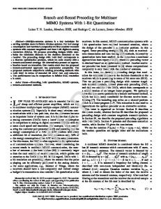
Fig. 3. Map showing the RSSI (in dBm) along the measurement routes. The position and the opening angle of the BS antenna are also indicated.
Fig. 4. CDF of the sum rate of SU-MIMO TDMA compared to MU-MIMO using a ZF and a MMSE precoder. The average SNR is fixed to 10dB for each user.
5. MEASUREMENTS AND RESULTS
and 1/σ 2 = 10 dB as the SNR at the receiver. Note, that this value is much less than the measurement SNR.
5.1. Scenario The measurements were conducted outdoors in the vicinity of the Eurecom institute. The scenario is characterized by a semi-urban hilly terrain, composed by short buildings and vegetation. Fig. 3 shows a map of the environment. The BS is located at the roof of one of the Eurecom buildings. The antenna is directed towards Garbejaire, a small nearby village. The UEs were placed inside standard passenger cars. The cars were only allowed to go to places with an RSSI > −90 dBm, so that they can still decode the BCH. This means that the UEs were in line of sight (LOS) of the BS most of the time. Otherwise, the cars had no fixed routes. For the presentation in this paper we selected one single measurement run of 50 sec duration. 5.2. Measurement Analysis The measurements result in the set of MIMO matrices {Hk,m,q , k = 0, . . . , 3, m = 0, . . . , 18749, q = 0, . . . , 39}. To ensure a constant average noise variance at the UEs, the channel of every user is normalized such that E{kHk k2F } = M N , where the expectation is taken over all m and q. The normalized MIMO channel matrices are then used to perform Monte-Carlo simulations of the sum rate of a ZF precoder, MMSE precoder and BD (cf. Equations (4), (6), and (9)). For SU-MIMO TDMA we simulate the average capacity of all the users, where the capacity of user k is calculated as (k)
RSU = log2 det(I +
P Hk HH k ). Nk σ 2
For all simulations we use P = 0 dB for the transmit power
5.3. Results and Discussion We compare the performance of a ZF precoder, MMSE precoder and BD (see Section 3) with that of a SU-MIMO TDMA scheme based on the empirical cumulative density function (CDF) of the sum rate. In Fig. 4 we compare the CDF of the sum rate of SUMIMO TDMA to MU-MIMO using a ZF and a MMSE precoder. There are four UEs with one receive antenna each (we ignore the second antenna). We show results for i.i.d. frequency-flat Rayleigh fading channel as well as the measured channel. The average SNR is fixed to 10dB for each user. It can be seen that the performance of all schemes is worse in the measured channel compared to the i.i.d. channels. This means that although the users have a large spatial separation, their channels are not i.i.d. Among all schemes, the ZF precoder has the worst performance (even worse than SU-MIMO TDMA). For the i.i.d. channel this fact has been observed and explained in [5] by looking at the condition number (ratio of largest to smallest eigenvalue) of HHH . For the measured channel, the condition number of HHH is even larger (see Fig. 5) and thus the performance of ZF in such channels is even worse. The MMSE precoder on the other hand overcomes this problem and performs twice as good than the SU-MIMO TDMA scheme. In Fig. 6 we compare the CDF of the sum rate of MUMIMO using a MMSE precoder and BD respectively. In the case of MMSE we serve four users simultaneously and we use the second receive antenna to perform antenna selection (AS): The wideband channel is grouped in chunks of 20 adjacent subcarriers and for every such chunk, the receive antenna
Empirical CDF of the condition number of H HH
MMSE vs. BD with maximum multiplexing gain
0
10
1
0.9
0.8
0.7
CDF
CDF
0.6
0.5
−1
10
0.4
0.3
0.2
MU−MIMO BD 2U iid MU−MIMO MMSE AS 4U iid MU−MIMO BD 2U measured MU−MIMO MMSE AS 4U measured
0.1 measured iid −2
10
0 0
100
200
300
400 500 600 condition number
700
800
900
1000
Fig. 5. CDF of the condition number (ratio smallest to largest eigenvalue) of the MU-MIMO channel HHH . with the higher receive energy (squared ℓ2 norm) is selected. In the case of BD, only two users are served, but the total number of streams stays the same (i.e., four). We show results for i.i.d. Rayleigh fading channel as well as for the measured channel. The average SNR is fixed to 10dB for each user. It can be seen that in the i.i.d. case, MMSE precoding with AS results in a higher sum rate that BD. However, this fact applies only partially for the measured channel. Here the median information rate (50% outage capacity) is larger for BD, but at a 1% outage capacity, MMSE with AS performs better. 6. CONCLUSIONS We have presented capacity analysis of linear MU-MIMO precoding schemes using real channel measurement data. The data was acquired using Eurecom’s MU-MIMO channel sounder EMOS. The results confirm the theory in the sense that MU-MIMO provides a higher throughput than SUMIMO TDMA without requiring multiple antennas at the receiver. The fact that the gains are not as large as predicted is due to the suboptimal linear precoder and the correlation in the measured channel. The increased throughput in MUMIMO comes at the cost of requiring full channel state information at the transmitter. It can be obtained by means of feedback in an FDD system or by exploiting channel reciprocity in a TDD system. Amongst all evaluated MU-MIMO precoding schemes, the MMSE precoder is the most favorable. Its performance is always superior to ZF, which suffers from the large eigenvalue spread of channel. When two receive antennas are available MMSE together with AS at the receiver also performs better than BD at 1% outage capacity. At the median information rate (50% outage capacity), BD performs slightly better. However, BD requires a more complex receiver design.
0
2
4
6
8 10 bits/sec/Hz
12
14
16
18
Fig. 6. CDF of the sum rate of MU-MIMO with 4 users using a MMSE precoder and AS compared to MU-MIMO with 2 users using BD. The average SNR is fixed to 10dB for each user. 7. REFERENCES [1] G. Caire and S. Shamai, “On the achievable throughput of a multiantenna gaussian broadcast channel,” IEEE Trans. Inf. Theory, vol. 49, no. 7, pp. 1691–1706, July 2003. [2] D. Gesbert, M. Kountouris, R. W. Heath Jr., C. B. Chae, and T. Salzer, “From single user to multiuser communications: Shifting the MIMO paradigm,” IEEE Signal Process. Mag., vol. 24, no. 5, pp. 36–46, Sept. 2007. [3] N. Jindal and A. Goldsmith, “Dirty-paper coding versus TDMA for MIMO broadcast channels,” IEEE Trans. Inf. Theory, vol. 51, no. 5, pp. 1783–1794, May 2005. [4] C. B. Peel, B. M. Hochwald, and A. L. Swindlehurst, “A vector-perturbation technique for near-capacity multiantenna multiuser communication-part I: channel inversion and regularization,” IEEE Trans. Commun., vol. 53, no. 1, pp. 195–202, Jan. 2005. [5] Q. H. Spencer, A. L. Swindlehurst, and M. Haardt, “Zero-forcing methods for downlink spatial multiplexing in multiuser MIMO channels,” IEEE Trans. Signal Process., vol. 52, no. 2, pp. 461–471, Feb. 2004. [6] R. de Lacerda, L. S. Cardoso, R. Knopp, M. Debbah, and D. Gesbert, “EMOS platform: real-time capacity estimation of MIMO channels in the UMTS-TDD band,” in Proc. International Symposium on Wireless Communication Systems (IWCS), Trondheim, Norway, Oct. 2007. [7] G. Bauch, J.B. Anderson, C. Guthy, M. Herdin, J. Nielsen, J. A. Nossek, P. Tejera, and W. Utschick, “Multiuser MIMO channel measurements and performance in a large office environment,” in Proc. IEEE Wireless Comm. and Net. Conf., Hong Kong, March 2007, pp. 1900–1905. [8] G. Bauch, P. Tejera, C. Guthy, W. Utschick, J. A. Nossek, M. Herdin, J. Nielsen, J. B. Andersen, E. Steinbach, and S. Khan, “Multiuser MIMO: Principle, performance in measured channels and applicable service,” in Proc. IEEE Veh. Technol. Conf. (VTC), Dublin, Ireland, Apr. 2007, pp. 2053–2057. [9] G. W. K. Colman and T. J. Willink, “Limited feedback precoding in realistic MIMO channel conditions limited feedback precoding in realistic MIMO channel conditions,” in Proc. IEEE Int. Conf. on Comm. (ICC), Glasgow, Scotland, June 2007, pp. 4363–4368. [10] M. Sharif and B. Hassibi, “A comparison of time-sharing, DPC, and beamforming for MIMO broadcast channels with many users,” IEEE Trans. Commun., vol. 55, no. 1, pp. 11–15, Jan. 2007.