ABSTRACT. We design an end-to-end linear transceiver in the downlink of a multi-user multiple-input multiple-output (MIMO) sys- tem with multiple data streams ...
LINEAR TRANSCEIVER DESIGN IN A MULTIUSER MIMO SYSTEM WITH QUANTIZED CHANNEL STATE INFORMATION Muhammad Nazmul Islam and Raviraj Adve Department of Electrical and Computer Engineering, University of Toronto 10 King’s College Road, Toronto, Ontario, M5S 3G4, Canada ABSTRACT We design an end-to-end linear transceiver in the downlink of a multi-user multiple-input multiple-output (MIMO) system with multiple data streams per user and quantized channel state information at the transmitter. We minimize the sum mean squared error (SMSE) under a sum power constraint with quantization based on the mean squared inner product. We make three contributions: (i) we remove dimensionality constraints on the MIMO configuration and the resulting feedback overhead scales linearly with the number of data streams; (ii) we use the combination of eigenmode combining and minimum mean square error receiver that makes user’s feedback mutually independent; (iii) we analyze SMSE at high signal-to-noise ratio and large number of transmit antennas and show the flooring effect of limited feedback systems in terms of SMSE. Index Terms: MU precoding, SMSE bounds, MSIP
data streams. Therefore, feedback overhead is spent only on the direction of those MISO channels and scales linearly with the number of transmit antennas and data streams. Grassmanian line packing [5], vector quantization (VQ) based on mean square error (MSE) [6] and random vector quantization (RVQ) [3, 7] have been the popular approaches for codebook generation in limited feedback. As an alternative, the authors in [8] propose maximizing MSIP as the codebook design criterion. We use this approach here. This paper makes the following contributions: we eliminate the dimensionality constraint and, using an eigenvector based combining, tie the feedback overhead to the number of data streams, which is necessarily smaller than the number of receiver antennas. This allows for the feedback scheme to be tied to an individual user. Finally we show the flooring effect of the SMSE for high SNR and large M ; previous work in this area has focused on the ceiling effect in terms of capacity [3, 9] and signal-to-interference-plus-noise ratio [6].
1. INTRODUCTION
2. SYSTEM MODEL
The benefits of multi-user (MU) multiple-input-multipleoutput(MIMO) systems are now well accepted [1–3]. These systems need to precode before transmitting the signals to combat receiver noise and MU interference; this in turn requires channel state information (CSI) at the transmitter. In both frequency division duplex and broadband time division duplex systems [4] the receiver can estimate, quantize and feedback the CSI to the transmitter. This paper deals with the feedback in a MU MIMO system with each user possibly receiving multiple data streams. Most of the relevant works in the literature deal with zero-forcing (ZF) beamforming [3] and therefore assume that the number of transmit antennas are greater than that of receive antennas (the dimensionality constraint) [3]. The authors in [2] use coordinated beamforming which avoid this constraint. However, �in [2], the feedback overhead is proportional to M 2 − 1 where M is the number of transmit antennas. Motivated by the need to minimize the overhead, in our work, each user projects its MIMO channel to its dominant eigenvectors and then quantizes the effective unit norm multiple-input-single-output (MISO) channel for the
We consider a single base station equipped with M transmit antennas and K independent users. User k has Nk P antennas and receives L data streams. We have L = k k Lk P th and N = N . The i data stream is processed by a k k unit norm linear precoding vector ui with the global precoder T U = [u1 , u2 , ..., uL ]. Let p = [p1 , p2 , .., pL ] be the allocated power to the data streams and define the downlink power matrix P = diag(p). ||p||1 ≤ Pmax . The overall � �T T data vector is x = [x1 , ...., xL ] = xT1 , xT2 , . . . , xTK . The Nk × M block fading channel, HH k , between the BS and the user is assumed to be flat. The global channel matrix is HH , with H = [H1 , ..., Hk ]. User k receives √ ykDL = HH (1) k U Px + nk , where nk represents the noise at the � � additive white Gaussian � � receiver with E nnH = σ 2 INk . Also, E xxH = IL . To estimate its own transmitted symbols, from ykDL , user k forms ˆ k = VkH ykDL . Let V be the N × L block diagonal global x decoder matrix, V = diag (V1 , ..., VK ). Overall √ √ ˆ = VH HH U Px + VH n = FH U Px + VH n (2) x
where, to facilitate our analysis, we define the M × L matrix F = HV with F = [f1 , . . . , fL ]. The vectors f1 , . . . , fL are the effective M × 1 channels for the individual data streams. In designing the precoder U, it is computationally efficient to use a virtual dual uplink [1]. Assume that in this T uplink the transmit powers are q = [q1 , .., qL ] for the L data streams. The global virtual uplink power allocation matrix Q is defined as, Q = diag(q). So, L X √ x ˆUL = uH fj qj xj + n (3) i i
BS, since we propose MMSE decoder while receiving data, the system performance remains invariant to this phase shift. e has M × L independent idenWe approximate that F tically distributed (i.i.d.) elements with zero mean and 2 2 σE /M variance. In [8] , σE is measured in terms of the angle spread between the original and the quantized vector, � � ��i h 2 2 ˆ e is inde. We also assume that F σE = E sin ∠ fk , fk b The use of MSIP ensures less angular pendent of x, n and F. 2 spread than than the use of MSE. This is mainly because σE −B for MSIP is upper bounded by 2 M −1 [8] whereas in VQ MSE, the average euclidean distance is lower bounded by −B 2 M [6]. MSIP therefore improves on the error exponent.
3. EIGENMODE BASED COMBINING AND MSIP
4. SMSE PRECODER DESIGN
We assume that the receivers have perfect channel knowledge. For the purposes of quantization only, each user uses, as Vk , the Lk singular vectors corresponding to the maximum singular values of Hk . This is unlike the MMSE solution in [1], but allows for the channel feedback to be independent of the other users’ actions. The channels are quantized after this eigenmode based combining (EBC). The quantization codebook is generated as a VQ problem using the MSIP optimality criterion [8]. Different quantization codebooks are generated for different data streams so that channels for multiple data streams are not quantized to the same codevector. Each codebook consists of 2B unit norm ˆ 1 , ..., w ˆ 2B and each user feeds back B bits for each vectors w of its data streams. The receivers individually normalize and then quantize the effective channels for the data streams as,
Let eDL be the MSE i h of the data streami i in the downlink where eDL = E (ˆ xi − xi ) (ˆ xi − xi )H . Then the SMSE i minimization problem can be formulated as,
j=1
To ensure resolvability, we assume L ≤ M and Lk ≤ Nk .
fi ||fi ||
b fi = arg
max
b {w b 1 ,..,w b 2B } w∈
H b |f i w|
(4)
where || · || denotes the euclidean norm. The quantization error e fi can be defined as, � � e fi = f i − b fiH f i b fi fi =
The channel model at the receiver takes the following form, fi
= ||fi ||f i �� � � = ||fi || b fiH f i b fi + e fi
(5)
Since we only send back the index of the unit norm b fi to the BS, we consider the following channel model at the BS, b +F e fi = b fi + e fi or F = F
(6)
ˆ Here F consists of L unit norm effective channel vectors. F e and F denote the quantized feedback and error � in feedback � respectively. Although there is a phase shift of b fiH f i between the original fi at the receiver and the assumed fi at the
min p,U
L X
eDL i
i=1
subject to : ||p||1 ≤ Pmax
(7)
It is computationally efficient to first solve the problem in the virtual uplink and then transfer the solution using duality. Using (3) for x ˆi the MSE in the virtual uplink is � �√ H FQFH + σ 2 I ui + 1 − uH eUL = uH qi i fi + fi ui i i ˆ + F, ˜ Using the fact that F = F eUL i
=
2 H Hˆ √ ˆ ˆH uH i FQF ui + σ ui ui + 1 − ui fi qi h i √ H e eH ˆ − qiˆ fi ui + E uH (8) i FQF ui |F
The last term in (8) can be written as,
h h ii PL q i 2 H H e ˜ ˜ ˆ EF˜ EFˆ uH FQ F u | F, F = i=1 σE ui ui (9) i i M 2 H Hˆ √ ˆ ˆH eUL = uH i i FQF ui + σ ui ui + 1 − ui fi qi √ σ2 − qi ˆfiH ui + E (q1 + .. + qL ) uH i ui M
(10)
√ The uplink MSE receiver is given by uMSE = J−1 ˆfi qi i J = eUL,MSE i
=
SM SE UL
=
2 ˆ H + σ 2 IM + σE (q1 + .. + qL ) IM (11) ˆ F FQ M √ √ 1 − qi ˆfiH J−1 ˆfi qi (12) L X
eUL,MSE = i
i=1
=
L−M +
L X i=1
2
σ +
1−
2 σE
L X √ ˆH −1ˆ √ qi fi J fi qi i=1
PL
i=1 qi
M
!
� � tr J−1 (13)
ˆ the SMSE where tr [·] denotes the trace operator. For fixed F, is a function of Q. Since, (13) remains a nonincreasing function of SNR with equal expected quantization error [10], power allocation becomes a convex optimization problem. A recent result shows that at the optimal solution and with the same power constraint, the same MSE can be achieved with p = q [11]. We use this in our work. Receiver Design: As mentioned earlier, the eigenbased combining is used for quantization purposes only. The base ˆ However, by sendstation determines p and U based on F. ing dedicated pilot symbol for each data stream, the receiver can implement the MMSE decoder through training and thus improve performance compared to the eigenbased decoder. Therefore, decoder for the ith stream is formed as, � √ H 2 −1 vi = HH HH (14) i UPU Hi + σ I i ui pi .
Here, ||vi || = 1. Hi is the channel of the user receiving ith stream. Overall Algorithm: The steps in the overall algorithm for MU MIMO SMSE minimization are: 1. BS sends common pilots to the users so that each user can estimate its own channel. 2. Each user converts its estimated MIMO channel to effective MISO channels using EBC. 3. Each user generates a codebook of 2B unit norm vectors using MSIP based VQ and then quantizes their effective channels and informs the BS. 4. Virtual uplink power � � allocation: PL σ2 q opt Q = minQ σ 2 + E Mi=1 i tr(J−1 ) s.t. tr[Q] = Pmax ; qk ≥ 0 is convex in Q √ 5. Uplink beamforming: ui = J−1 ˆfi qi , ||ui || = 1 6. Downlink power allocation p = q 7. BS sends dedicated pilot symbols for each of the data streams. Thereafter, each user finds vi using (14) and through training. The algorithm above results in a precoder, U, decoder, V and power allocation, p. Note that the solution is sub-optimal because U and p are designed based on the EBC receiver, not an SMSE criterion. 5. ASYMPTOTIC SMSE ANALYSIS In this section we analyze the estimated SMSE at the base station, at high SNR and for large M . To simplify the analysis we assume equal power allocation. Using (12) and (11) and the fact that qi = Pmax /L, � �−1 2 σ2 σE UL H H ˆ ˆfi , (15) ˆ ˆ ei = 1 − fi FF + IM + LIM qi M since Q = qi IL . At high SNR, the second term in the bracket is negligible. Let 2 ˆ H + σ IM = UDUH ˆF F qi
We have eUL,MSE i
= =
�−1 � 2 σE H ˆfi LIM UDU + M 1 − ˆf H U(D + C)−1 UH ˆfi (16)
1 − ˆfiH i
σ2
In (16) we assume that every diagonal element in C is ME L. All the ˆ f vectors fed back to the transmitter are unit norm and statistically independent with each other. Therefore, using the channel model at the base station (6), if we keep increasing M while keeping L fixed, then by the law of large ˆF ˆ H fˆi = 1 [6]. numbers,limM→∞ ˆfiH F This, in turn, leads to, limM→∞ ˆfiH UDUH ˆfi = 1. Without loss of generaility, we can assume that ˆfi constitutes one of the eigenvectors of U and the corresponding eigenvalue in D is 1. Therefore, eUL,MMSE i
= 1− =
1 1+
2 LσE M
2 LσE 2 M + LσE
(17)
Since, this finds the uplink MSE for one data stream, lim
SN R,M→∞
SM SE =
2 L2 σE 2 M + LσE
(18)
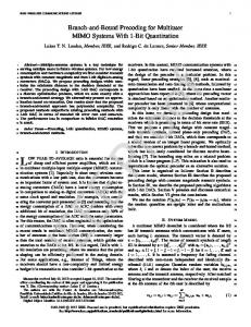
The estimated SMSE at the BS (18) leads to the following result. For a fixed quantization error, the SMSE of a multiuser system is lower bounded by a fixed value which does not depend on SNR. We call this the flooring effect of multiuser broadcast systems. This is similar to the ceiling effect, in terms of capacity and SINR, seen previously in limited feedback literature [3, 6]. 6. SIMULATION RESULTS In Fig. 1 the proposed algorithm’s performance is compared with that of coordinated beamforming [2]. Since [2] implements joint transceiver design, it performs better than the proposed algorithm with full CSIT. �However, coordinated beamforming needs at least M 2 − 1 bits for the feedback ˆ H . 15 bits per user means 1 bit per unique scalar ˆH of H entry of that matrix which is very low. On the other hand, the proposed algorithm projects the data into the most dominant eigenvector and quantizes that with an error of only −B 2 M −1 = 0.03125. Thus, the proposed algorithm performs very close to its full CSIT curve and outperforms [2] with limited feedback. In Fig. 2, the performance of the proposed algorithm is compared with that of ZF and random vector quantization (RVQ) based QBC algorithm which projects the data streams in the least quantization error directions [9]. Since, [9] does not require second phase training, we also show the proposed
M=4,N=[4 4],L=[1 1],15 bit per user
0
10
0
10
Coordinate beamforming limited feedback Proposed algo limited feedback Coordinate beamforming full CSIT Proposed algo full CSIT
−1
10
proposed algo(Ideal MMSE receiver) ZF QBC proposed algo(estimated MMSE receiver)
Average BER
−1
−2
Average BER
10
−3
10
10
−2
10
−4
10
−5
10
−3
10 −6
10 −10
−8
−6
−4
−2
0 2 SNR (in dB)
4
6
8
10
Fig. 1. Comparison with the co-ordinated beamforming M = 4, N = [4 4], L = [1 1], 15 bits per user, QPSK algorithm’s performance with an estimated MMSE receiver, implemented with 8 training symbols. By using SMSE precoder and MMSE receiver, coming at the cost of training symbols, the proposed algorithm performs better than [9]. 7. CONCLUSION In this work, we proposed linear transceiver design in a MU MIMO system to minimize SMSE under a sum power constraint with limited feedback. We used an eigenmode based combining scheme to reduce the MIMO problem to a MISO situation and use MSIP for effective channel quantization. However, this is done only for the feedback and the receiver improves performance by using a MMSE decoder while receiving data. We analyzed SMSE asymptotically under some simplifying conditions. Our future works will incorporate channel gain feedback along with the proposed limited shape feedback and analyze the overall scheme. 8. REFERENCES [1] A. M. Khachan, A. J. Tenenbaum, and R. S. Adve, “Linear processing for the downlink in multiuser MIMO systems with multiple data streams,” in Proc. IEEE ICC’2006, June 2006, vol. 9, pp. 4113–4118. [2] C. Chae, D. Mazzarese, N. Jindal, and R. W. Heath Jr, “Coordinated beamforming with limited feedback in the MIMO broadcast channel,” IEEE Journal of Selected Areas in Communications, vol. 26, pp. 1505–1515, Oct. 2008. [3] N. Jindal, “MIMO broadcast channels with finite-rate
0
5
10
15
20
SNR (in dB)
Fig. 2. Comparison with the ZF-QBC, M = 4, N = [3 3], L = [2 2], QPSK, 12 bit per user feedback,” IEEE Transactions on Communications, vol. 52, pp. 5045–5060, Nov. 2006. [4] J. C. Haartsen, “Impact of non-reciprocal channel conditions in broadband TDD systems,” in Proc. IEEE PIMRC’2008, Sept. 2008, pp. 1–5. [5] D. J. Love, R. W. Heath Jr., and T. Strohmer, “Grassmanian beam-forming for multiple-input multiple-output wireless systems,” IEEE Transactions on Information Theory, vol. 49, pp. 2735–2747, Oct. 2003. [6] A. D. Dabbagh and D. J. Love, “Multiple antenna MMSE based downlink precoding with quantized feedback or channel mismatch,” IEEE Transactions on Communications, vol. 7, pp. 1859–1868, Nov. 2008. [7] N. Ravindran and N. Jindal, “Limited feedback-based block diagonalization for the MIMO broadcast channel,” IEEE Journal on Selected Areas in Communications, vol. 26, pp. 1473–1482, Oct. 2008. [8] J. C. Roh and B. D. Rao, “Transmit beamforming in multiple-antenna system with finite rate feedback: A VQ-based approach,” IEEE Transactions on Information Theory, vol. 52, pp. 1101–1112, Mar. 2006. [9] N. Jindal, “Antenna combining for the MIMO downlink channel,” IEEE Transactions on Wireless Communications, vol. 7, pp. 3834–3844, Oct. 2008. [10] M. Ding, Multiple-input multiple-output system design with imperferct channel knowledge, Ph.D. thesis, Queen’s University, 2008. [11] A. Tenenbaum and R. S. Adve, “Minimizing sum-MSE implies identical downlink and dual uplink power allocations,” IT Archive, Dec. 2009.