Research Article www.acsami.org
Carbon Nanotube Synaptic Transistor Network for Pattern Recognition Sungho Kim,† Jinsu Yoon,‡ Hee-Dong Kim,† and Sung-Jin Choi*,‡ †
Department of Electrical Engineering, Sejong University, Seoul 05006, Korea School of Electrical Engineering, Kookmin University, Seoul 02707, Korea
‡
S Supporting Information *
ABSTRACT: Inspired by the human brain, a neuromorphic system combining complementary metal-oxide semiconductor (CMOS) and adjustable synaptic devices may offer new computing paradigms by enabling massive neural-network parallelism. In particular, synaptic devices, which are capable of emulating the functions of biological synapses, are used as the essential building blocks for an information storage and processing system. However, previous synaptic devices based on two-terminal resistive devices remain challenging because of their variability and specific physical mechanisms of resistance change, which lead to a bottleneck in the implementation of a high-density synaptic device network. Here we report that a three-terminal synaptic transistor based on carbon nanotubes can provide reliable synaptic functions that encode relative timing and regulate weight change. In addition, using system-level simulations, the developed synaptic transistor network associated with CMOS circuits can perform unsupervised learning for pattern recognition using a simplified spike-timing-dependent plasticity scheme. KEYWORDS: analog switching, carbon nanotube, neuromorphic system, pattern recognition, synaptic device, transistor
■
INTRODUCTION The human brain is an exceptionally energy-efficient computing system specialized in perception, recognition, learning, and decision making. Although modern computers can similarly execute such tasks, they require many more orders of magnitude energy and complex programming. Artificial neural networks are inspired by the human brain, and unlike conventional von Neumann type computers, these networks enable adaptable and high-efficiency computing because of the massive parallelism of neurons and synapses.1,2 For information processing in neural networks, spikes from the presynaptic neurons can be transmitted through the synapses and generate a membrane potential; thus, presynaptic spikes are based on the relative strengths of the synapses (i.e., the synaptic weights). These synaptic weights can be modulated by the spikes from pre- and postsynaptic neurons and can be maintained over the long-term; thus, the plasticity of the synaptic weights enables learning and memory operations in the system.3 To date, the functions of neurons and synapses have been emulated by circuits combining complementary metal-oxide semiconductor (CMOS) and adjustable two-terminal resistive devices (memristors). In particular, critical synaptic-learning rules (i.e., spike-timing-dependent plasticity (STDP)) have been demonstrated by memristors in a number of studies.4−9 Theoretical studies have suggested that STDP can be used for learning in spiking neural networks;10,11 therefore, memristors have been considered as promising candidates for electrical synapse devices. As discussed in previous studies, however, the © 2015 American Chemical Society
sustainability of memristors is still in doubt, particularly with regards to the device-to-device variability that is common to all memristor technologies.12 The specific physical mechanism of resistance change in most prospective metal-oxide-based memristors, which is a reversible atomic-scale modulation of oxygen vacancies,13 is responsible for the unwanted device-todevice reproducibility issue of relevant device parameters, which is the primary reason why the only demonstrations of memristor neuromorphic networks have been based on disconnecting each memristor14,15 or the use of low-density crossbar arrays.16 These approaches are incompatible with the goal of achieving extremely high-density neuromorphic networks. In this study, we demonstrate an electronic synapse device based on carbon nanotube (CNT) three-terminal transistors and show that by controlling the internal dynamics of CNT synaptic transistors reliable long-term synaptic functionality (i.e., STDP) can be achieved. To reduce the synaptic-device variability, we used a preseparated, semiconducting-enriched single-walled CNT matrix, which potentially enables a largescale neuromorphic circuit with a high uniformity. We used a system-level simulation based on a simplified STDP scheme for a CNT synaptic transistor network, which shows the potential for unsupervised learning and consequent pattern recognition Received: September 11, 2015 Accepted: October 29, 2015 Published: October 29, 2015 25479
DOI: 10.1021/acsami.5b08541 ACS Appl. Mater. Interfaces 2015, 7, 25479−25486
Research Article
ACS Applied Materials & Interfaces
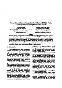
Figure 1. CNT synaptic transistor. (a) Schematic illustration showing a synapse connecting a pair of neurons, where the synaptic functions can be emulated by synaptic transistors. (b) Basic neuromorphic unit that comprises several synapses and a neuron. This unit mimics a biological neuron, where the synapse receives spikes from preneurons and converts them into currents on the basis of their synaptic strength. The postneuron performs a spatiotemporal integration of the spikes and generates output spikes (or action potentials). (c) Device schematic for the demonstrated CNT synaptic transistor and an atomic force microscopy image (5 μm × 2.5 μm, z scale is 10 nm) of the single-walled CNT matrix deposited onto Si/SiO2 substrates.
(I&F) circuit based on common Si transistors.17,18 However, the emulation of a synapse is relatively challenging because of its unique characteristics, which include being nonvolatile and having the ability to modulate its analogue state. In this study, the synaptic transistors based on a random matrix of singlewalled CNTs are shown to reproduce synaptic functions (Figure 1b,c). Preseparated, semiconducting CNTs (90%) enable high uniformity and sustainability of the synaptic transistors and reliable synaptic functions (Supporting Information Note 2). In principle, neurons transmit signals thorough the CNT synaptic transistor channel, where the transistor’s gate and source electrodes are connected to the preneuron (input neuron) and the postneuron (output neuron), respectively. The channel conductance of the CNT synaptic transistors can be controlled via the presynaptic spike (Vpre), which is applied to the gate, and postsynaptic spike (Vpost), which is applied to the source. Thus, the variable channel conductance of a CNT synaptic transistor will be used as a synaptic weight. In addition, each CNT synaptic transistor has a shared output channel to a given output neuron, as shown in Figure 1b. Presynaptic spikes from input neurons can trigger multiple CNT synaptic transistors simultaneously, and all postsynaptic currents generated from CNT synaptic transistors are collected and accumulated at an output neuron (by I&F circuits). In detail, input presynaptic spikes represent sensing signals from the external environment. The timing and rate of these spikes represent the analogue information on the sensing signals from the sensors. These input spikes lead to postsynaptic currents, which are determined on the basis of the channel conductance of each CNT synaptic transistor. Then, all postsynaptic currents are accumulated at an output neuron, which fires postsynaptic spikes back to the CNT synaptic transistor if the accumulated postsynaptic current level is above a given threshold value. On the basis of the relative timing of the pre- and postsynaptic spikes, the synaptic weight can be modulated to any analogue state and memorized over the longterm.
ability. These simulation results can provide guidelines for continued design and optimization of CNT synaptic transistors to produce a large-scale, neuromorphic computing system.
■
EXPERIMENTAL SECTION
A highly p-doped silicon substrate was used as the back gate with thermally grown, 55 nm thick, back-gate oxide (SiO2). The substrate was first functionalized with a poly(L-lysine) solution to form an amine-terminated layer, which acted as an effective adhesion layer for single-walled CNTs. The substrate was then rinsed with deionized (DI) water and isopropanol. To deposit a random matrix of CNTs, the substrate was immersed in a high-purity, semiconducting nanotube solution for 1 min, followed by a thorough rinse with DI water and then isopropanol and DI water; the substrate was then dried with flowing nitrogen. The 90% semiconducting nanotube solutions (IsoNanotubes-S) used in this study were provided by Nanointegris, Inc. The source/drain electrodes were inkjet-printed with silver (Ag) nanoparticle ink (InkTec Tec-IJ-060) using an inkjet printer (Unijet UJ200MF) integrated with a piezoelectric-type dispenser and 50 μm orifice nozzles. Prior to inkjet printing, Ag ink was filtered through a 5 μm polytetrafluoroethylene (PTFE) syringe filter to avoid aggregation of Ag nanoparticles. The typical inkjet droplet volume ranged from 40 to 50 pL. Subsequently, a 150 °C annealing process was employed. Finally, poly(4-vinylphenol) (PVP) was also printed onto the surface to designate the active channel area. A subsequent oxygen plasmaetching step was carried out to isolate the devices and remove undesirable leakage paths. The PVP was then sequentially removed with acetone, isopropanol, and flowing nitrogen. The channel lengths and widths of the fabricated device were 170−480 μm and 300−490 μm, respectively. (Microscopy image of the fabricated devices is shown in Supporting Information Note 1.) Electrical measurements were conducted using a low-noise Keithley 4200 semiconductor characterization system or a custom-built electrical measurement system in combination with a probe station. During all measurements, the bias voltage was always applied to the gate, the source, and the drain electrodes.
■
RESULTS AND DISCUSSION The base module of the neuromorphic system reproduces the interrelation of a presynaptic neuron connected with other postsynaptic neurons via synapses (Figure 1a). In general, neurons can be easily emulated using an integrate-and-fire 25480
DOI: 10.1021/acsami.5b08541 ACS Appl. Mater. Interfaces 2015, 7, 25479−25486
Research Article
ACS Applied Materials & Interfaces
Figure 2. Analogue conductance modulation behavior. (a) Hysteresis of the source current (IS) as a function of the gate voltage (VG) with a constant drain voltage (VD = −1 V). The hysteresis loop direction is anticlockwise, which indicates that a positive VG increases the channel conductance and a negative VG decreases the conductance. The channel conductance was measured at a specific read voltage (Vread = −3 V) because this Vread is insufficient to modulate the channel conductance. (b) Schematics of the applied pulse trains used to measure the analogue switching behavior. Each pulse train consists of 75 potentiation or depression pulses (5 and −5 V for 10 ms) followed by small, nonperturbative read voltage pulses (−3 V for 100 ms) within the intervals. The conductance was measured during the read pulse and plotted as a function of the applied pulse number.
Figure 3. Plots showing the ability to control the channel conductance with the gate/source terminals. (a) Schematics of the applied pulse trains used for the measurement. Each pulse train consists of 75 potentiation or depression pulses applied to the gate (6 and −6 V for 10 ms) along with a different source voltage pulse (0 or −1 V). (b) Measured analogue conductance-switching behaviors based on different VGS. (c) Implementing STDP using a CNT synaptic transistor. The prespike voltage (Vpre) and postspike voltage (Vpost) are applied to the gate and source of the synaptic transistor, respectively. The net programming voltage (Vpre − Vpost) applied across the device depends on the positive or negative moments Δt. The symbols in the figure indicate experimental data, and the lines are guides for the reader.
channel conductance-switching behavior, which is described in detail in Supporting Information Note 3. In fact, hysteresis has frequently been observed in CNT transistors and is difficult to eliminate. As reported in other studies,20,21 the modification of transistor structures and use of hydrophobic film may reduce the hysteresis; therefore, the additional charge trap layer might be necessary to allow electrons or holes to be trapped or detrapped reliably. However, we intentionally utilized the backgate transistor structure in this work, which is exposed to the ambient environment, and large hysteresis was obtained for neuromorphic network operation. To identify the analogue conductance-switching behavior in a synaptic transistor, Figure 2b shows the schematics of the pulse trains used for the measurement. Each pulse train consists of 75 pulses (+5 V for potentiation and −5 V for depression) followed by nonperturbative read voltage pulses at −3 V within the intervals.
First, as mentioned above, the synaptic weight can be reproduced by an intrinsic analogue state of channel conductance in the CNT synaptic transistor. When the gate voltage (VG) was swept from −7 to +5 V and back to −7 V, a hysteresis of the source current (IS) under a constant drain voltage (VD) was observed (Figure 2a); a positive VG increased the channel conductance, which is defined as the “potentiation” of the synaptic weight, and a negative VG decreased the conductance, which is defined as the “depression” of the synaptic weight. This hysteresis indicates an intrinsic characteristic of the variable channel conductance in the CNT synaptic transistor that is dependent on the control of VG. The hysteresis in the CNT transistor may stem from charge trapping in water molecules around the CNT, where the CNT is exposed to the ambient environment.19 The trapping/detrapping effect of carriers provides internal dynamics that drive the analogue25481
DOI: 10.1021/acsami.5b08541 ACS Appl. Mater. Interfaces 2015, 7, 25479−25486
Research Article
ACS Applied Materials & Interfaces
Figure 4. Pattern recognition simulation. (a) Learning and testing operation sequences of the CNT synaptic transistor network. The MNIST database consisting of handwritten numbers of 28 pixels × 28 pixels was used to verify the pattern recognition potential of this method. The full MNIST training database (60 000 digits) was input to the system, and input presynaptic spikes generate postsynaptic currents, which are then integrated by the output neurons. Then, one neuron fires postsynaptic spikes; thus, correlated pre- and postresynaptic spikes result in channelconductance potentiation or depression (i.e., the learning process). After finishing the learning process, the network is then tested on the MNIST test database, which consists of 10 000 digits that were not available during training. (b) Architecture of the CNT synaptic transistor network, consisting of 28 × 28 input neurons and 10 output neurons. Lateral inhibition between the output neurons is also implemented. (c) Pulses for simplified STDP (voltage pulses as functions of time). The net voltage difference (VGS = Vpre − Vpost) is applied to the device at the moments of a positive or negative time interval (Δt). The polarity of VGS is determined by Δt; VGS is positive when Δt > tpre for potentiation and negative when Δt < tpre for depression.
depression, respectively, while changing the source pulse amplitude from 0 to −1 V during repeated potentiation and depression processes, Figure 3b shows the evolution of the channel conductance as a function of the net voltage difference between the gate and source pulses (VGS). As shown in Figure 3b, distinctive analogue conductance-switching behaviors were observed to be dependent on VGS; a higher |VGS| was found to yield a larger conductance change. When VS = −1 V during the potentiation process, i.e., VGS = +7 V, a larger ΔG was obtained than that in the case of VGS = +6 V (i.e., VS = 0 V). Similarly, when VS = −1 V during the depression process, i.e., VGS = −5 V, a smaller ΔG was obtained than that in the case of VGS = −6 V (i.e., VS = 0 V). This phenomenon occurred because a higher VGS causes more trapping of carriers during the potentiation process, which results in a larger increase in conductance. Similarly, a higher |VGS| during the depression process enhances the detrapping process, thus leading to a larger decrease in conductance. As a result, the channel conductance of a CNT synaptic transistor can be controlled on the basis of the net voltage difference between the gate and source terminals, which enables the emulation of the STDP effect based on the temporally correlated pre- and postsynaptic spikes. In particular, the ability to control the channel conductance from the correlated VG and VS voltages is clearly distinct from
Note that the measured channel conductance (G) during the applied pulse trains show a gradual transition in both potentiation and depression responses. In particular, the range of the analogue conductance modulation (ΔG = maximum G − minimum G) is approximately 100%, which is clearly distinct from the previous memristor-based synaptic devices, whose modulation range of conductance is at most 30%.4,22 A larger ΔG margin enables more efficient learning and pattern recognition in neuromorphic network operation, which is discussed later; this is a notable merit of the demonstrated CNT synaptic transistor compared to previous memristors. Next, the synaptic learning rule (STDP) refers to the effect that the relative timing of pre- and postsynaptic spikes determines the sign and magnitude of the long-term synaptic weight change. The long-term modification of channel conductance in a CNT synaptic transistor should be reproducible by a pair of temporally correlated gate (VG) and source (VS) voltages. To study systematically how the channel conductance is affected by VG and VS, the potentiation and depression responses of the channel conductance in a CNT synaptic transistor were measured at different VG/VS pulse configurations, as shown in Figure 3a. By keeping the gate pulse amplitude constant at +6 and −6 V for potentiation and 25482
DOI: 10.1021/acsami.5b08541 ACS Appl. Mater. Interfaces 2015, 7, 25479−25486
Research Article
ACS Applied Materials & Interfaces previous CNT synaptic transistors;23,24 because channel conductance modulation was only possible through the gate terminal, either the STDP effect was not reproducible23 or two paired-transistors were used to implement the potentiation/ depression processes,24 which are inefficient methods to produce a large-scale neuromorphic system. Because of this distinctive controllability of channel conductance in our CNT synaptic transistors, the learning rule (STDP) was consequently explored using a designed spike paring protocol. The bipolar, saw-edged pulses shown in Figure 3c were used for both preand postsynaptic spikes (Vpre and Vpost), where Vpre and Vpost are applied to the gate and the source terminals, respectively. Then, the net voltage difference (VGS = Vpre − Vpost) is applied to the device at the moments of a positive or negative time interval (Δt). The polarity of VGS is determined by the sign of Δt; VGS is positive when Δt > 0 for potentiation and negative when Δt < 0 for depression. Figure 3c shows the measured rate of conductance change as a function of the relative timing of the pre- and postsynaptic spike applications, which is indeed consistent with the biological data measured in hippocampal glutamatergic synapses measured by Bi and Poo. (The longterm characteristic of STDP is verified in Supporting Information Note 4.)3 Significantly, the change in conductance is shown to depend on the voltage difference between the two terminals, which is a key factor in implementing a CNT synaptic transistor network, as discussed below. Here we present system-level simulation results using a simplified STDP scheme25 and show how the demonstrated CNT synaptic transistors associated with CMOS neuron circuits can perform unsupervised learning and pattern recognition (Figure 4a). The detailed simulation parameters and model used in this study are described in Supporting Information Note 5. In principle, sensors will sense the external environment and then convert the sensed information into the presynaptic spikes with timings. When an input neuron fires a presynaptic spike (Vpre), this spike is applied to the gate terminal of a synaptic transistor during tpre (Figure 4b,c). Vpre is sufficient to drive a postsynaptic current in a synaptic transistor but not sufficient to modulate the channel conductance for potentiation/depression. Next, the postsynaptic current is integrated by the output neurons through I&F circuits based on CMOS. Because many synaptic transistors connected to the same output neuron are active concurrently, their postsynaptic currents are summed. If the accumulated postsynaptic current level is above the threshold value, then the output neuron fires a postsynaptic spike (Vpost) back to the source terminal of the synaptic transistor. Thus, a time interval (Δt) between Vpre and Vpost exists. As shown in Figure 4c, if no Vpre pulse is applied to the device (Δt > tpre), then the net voltage difference applied to the gate/source terminals (VGS = Vpre − Vpost) is sufficient to initiate the potentiation process, which can increase the channel conductance. Conversely, if the input neuron has fired recently and Vpre is still being applied to the device, then VGS actually decreases the channel conductance. To model the modulation of the channel conductance on the basis of VGS in the proposed system simulations, we use the measured data shown in Figure 2b. An increase in the channel conductance is fitted by the equation δGp = γp + αp e−βp(G − Gmin)/(Gmax − Gmin)
δGd = γd + αd e−βd(Gmax − G)/(Gmax − Gmin)
(2)
In this simplified model, the change in channel conductance is only dependent on the present conductance value (G), which is not consistent with the STDP effect shown in Figure 3c. In a real biological system, an enhanced change in the synaptic weight (channel conductance) occurs as the time interval (Δt) between Vpre and Vpost is shortened. Therefore, for the purely bioinspired system simulation, the model should consider the effect of Δt. However, compared with the complex pulse waveform shown in Figure 3c that creates the STDP effect, no bipolar saw-edged pulse is necessary for the Vpre and Vpost waveforms in the simplified scheme, which should make the neuron circuitry much easier to design. In addition, the analogue conductance-switching data shown in Figure 2b are only required for the system simulation, which enables an efficient analysis of a neuromorphic system within a shorter simulation time. Therefore, we use a simplified STDP scheme that is easier to implement. Next, as mentioned earlier, the neuron functions can be emulated using an I&F circuit that allows neurons to generate spikes and integrate their input, which is meant to solve the simple following equation: τ
dX + X = Iinput dt
(3)
where we define the state variable (X) as an integrated postsynaptic current (Iinput) and τ as a leak-time constant. The neuron fires a postsynaptic spike if X reaches a given threshold, Xth. In addition, when an output neuron fires spikes, it sends inhibitory signals to the other output neurons that prevent them from firing during the specific inhibition time and resets their X values to zero, which is known as the “winner takes all” rule.26 Simple algorithms for the homeostasis27 effect were included in these simulations. A target activity (i.e., the number of times an output neuron should fire within the total simulation time) is defined for the neurons. Then, the threshold of the neuron (Xth) is increased if the average activity of the neuron is above the target and decreased if it is below the target: dX th = γ (A − T ) dt
(4)
where A is the mean firing rate of a neuron, T is the target activity, and γ is a constant. Accordingly, all thresholds of the output neurons are adjusted continuously, where Xth increases if the specific neuron fires more than others and Xth decreases if the specific neuron fires less than others. To demonstrate pattern recognition in a CNT synaptic transistor network, we use the widely studied case of handwritten number recognition using the MNIST database, which consists of handwritten number that are 28 pixels × 28 pixels from 250 writers.28 To guide the learning process, we input the full MNIST training database, which consists of 60 000 digits, into the system. Each input neuron is connected with 1 pixel of the image; thus, a total of 28 input neurons × 28 input neurons emit presynaptic spikes that are proportional to the pixel intensity, as shown in Figure 4a. On the basis of the synaptic weight of each synaptic transistor, input presynaptic spikes generate postsynaptic currents that are integrated by output neurons. Then, the one neuron whose integrated postsynaptic current is the highest fires postsynaptic spikes (Figure 4b); correlated pre- and post- resynaptic spikes result in
(1)
Similarly, a decrease in the channel conductance is described by 25483
DOI: 10.1021/acsami.5b08541 ACS Appl. Mater. Interfaces 2015, 7, 25479−25486
Research Article
ACS Applied Materials & Interfaces
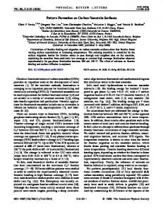
Figure 5. Simulation results. (a) Channel conductance (synaptic weights) learned in a simulation with ten output neurons (N1 to N10). Red indicates a minimum conductance, and blue indicates a maximum conductance. (b) Number of firings that each neuron creates in the case of the digit “1” and the digit “9” after 60 000 training instances. (c) Recognition rate from the test data set as a function of the training number. Each simulation was repeated five times, and the error bars describe the range of values observed from their minimum to their maximum values. (d) Measured and arbitrarily designed analogue conductance-switching behaviors to investigate the influence of the conductance modulation range on the recognition rate of the network. (e) Simulation results showing the recognition rate based on the different analogue conductance-switching behaviors.
channel-conductance potentiation or depression (i.e., the learning process). After completing the learning process, the network is then tested on the MNIST test database, which consists of 10 000 digits that were not available during training. Figure 5a plots the channel conductance learned by the synaptic transistor network in a configuration with ten output neurons (N1−N10). It is shown that without any supervision and using only a simplified STDP rule the network learns and memorizes 10 different numbers. To evaluate the capability of the system, we define the recognition rate (RR); for example, as shown in Figure 5b, when the digit “1” is input to the system during the testing process, the N4 neuron primarily fires, which indicates that the integrated postsynaptic current through the N4 neuron is larger than that of the other neurons. This occurs because input presynaptic spikes that convert the pixel intensity information on the digit “1” are well-matched to the trained synaptic weight of the synapses connected with the N4 neuron, which leads to the largest postsynaptic currents. However, the digit “1” also can cause other neurons to fire occasionally (i.e., a recognition error). This error is worse in the case of the digit “9”, as shown in Figure 5b because the digit “9” can be confused with the digits “4” or “7”. To quantitatively evaluate the network’s recognition rate, Figure 5c plots the average recognition rate of the ten numbers. With ten output neurons, the recognition rate reaches 60% after 60 000 training instances and can be increased as the number of training is increased. Additionally, to provide a guideline on how to improve the recognition rate, we investigate the influence of the conductance-switching margin in synaptic transistors on the recognition rate of the network. For this study, we arbitrarily design two different analogue conductance-switching behaviors,
as shown in Figure 5d. Case 1 has a larger range of conductance modulation (ΔG) compared with the measured data shown in Figure 2b. Conversely, case 2 has a smaller ΔG, so the recognition rate, which is dependent on ΔG, can be investigated by simulation. Figure 5e shows the simulation results with different ΔG cases and shows that the recognition rate is significantly affected by ΔG, where a larger ΔG produces a better recognition rate. This result indicates that ΔG is an important parameter in synaptic devices. The demonstrated CNT synaptic transistor is shown to have a larger ΔG margin than previous memristor-based synaptic devices, which enables more efficient pattern recognition in a neuromorphic network.
■
CONCLUSIONS In this study, we have experimentally demonstrated an electronic synapse device based on CNT transistors with reliable analogue conductance-modulation behavior. Specifically, the internal dynamics of a CNT transistor enables a native mechanism to encode the synaptic-weight plasticity through the gate/source terminals. These findings facilitate the potential development of a large-scale CNT synaptic transistor network without having to consider device-to-device variability. Additionally, a simplified STDP scheme was used to simulate the network at a system level, where CNT synaptic transistors associated with CMOS neuromorphic circuits could perform unsupervised learning and pattern recognition. The range of conductance modulation in CNT transistors is significantly larger than that of typical memristors, which enables a better recognition rate during pattern-recognition operations. This simulation result is an important step toward the effective analogue hardware implementation of more complex neuro25484
DOI: 10.1021/acsami.5b08541 ACS Appl. Mater. Interfaces 2015, 7, 25479−25486
Research Article
ACS Applied Materials & Interfaces
(7) Krzysteczko, P.; Munchenberger, J.; Schafers, M.; Reiss, G.; Thomas, A. The Memristive Magnetic Tunnel Junction as a Nanoscopic Synapse-Neuron System. Adv. Mater. 2012, 24, 762−766. (8) Wang, Z. Q.; Xu, H. Y.; Li, X. H.; Yu, H.; Liu, Y. C.; Zhu, X. J. Synaptic Learning and Memory Functions Achieved Using Oxygen Ion Migration/Diffusion in an Amorphous InGaZnO Memristor. Adv. Funct. Mater. 2012, 22, 2759−2765. (9) Zamarreno-Ramos, C.; Camunas-Mesa, L. A.; Perez-Carrasco, J. A.; Masquelier, T.; Serrano-Gotarredona, T.; Linares-Barranco, B. On Spike-Timing-Dependent-Plasticity, Memristive Devices, and Building a Self-Learning Visual Cortex. Front. Neurosci. 2011, 5, 26. (10) Masquelier, T.; Thorpe, S. J. Unsupervised Learning of Visual Features through Spike Timing Dependent Plasticity. PLoS Comput. Biol. 2007, 3, e31. (11) Nessler, B.; Pfeiffer, M.; Buesing, L.; Maass, W. Bayesian Computation Emerges in Generic Cortical Microcircuits through Spike-Timing-Dependent Plasticity. PLoS Comput. Biol. 2013, 9, e1003037. (12) Kim, K. H.; Gaba, S.; Wheeler, D.; Cruz-Albrecht, J. M.; Hussain, T.; Srinivasa, N.; Lu, W. A Functional Hybrid Memristor Crossbar-Array/CMOS System for Data Storage and Neuromorphic Applications. Nano Lett. 2012, 12, 389−395. (13) Wong, H. S. P.; Lee, H. − Y.; Yu, S.; Chen, Y. − S.; Wu, Y.; Chen, P. − S.; Lee, B.; Chen, F. T.; Tsai, M. − J. Metal-Oxide RRAM. Proc. IEEE 2012, 100, 1951−1970. (14) Alibart, F.; Zamanidoost, E.; Strukov, D. B. Pattern Classification by Memristive Crossbar Circuits with Ex-Situ and InSitu Training. Nat. Commun. 2013, 4, 2072. (15) Eryilmaz, S. B.; Kuzum, D.; Jeyasingh, R.; Kim, S. B.; BrightSky, M.; Lam, C.; Wong, H. S. P. Brain-Like Associative Learning Using a Nanoscale Non-Volatile Phase Change Synaptic Device Array. Front. Neurosci. 2014, 8, 205. (16) Prezioso, M.; Merrikh-Bayat, F.; Hoskins, B. D.; Adam, G. C.; Likharev, K. K.; Strukov, D. B. Training and Operation of an Integrated Neuromorphic Network Based on Metal-Oxide Memristors. Nature 2015, 521, 61−64. (17) Indiveri, G.; Chicca, E.; Douglas, R. A VLSI Array of Low-Power Spiking Neurons and Bistable Synapses with Spike-Timing Dependent Plasticity. IEEE Trans. Neural Netw. Learn. Syst. 2006, 17, 211−221. (18) Liu, S.-C.; Douglas, R. Temporal Coding in a Silicon Network of Integrate-and-Fire Neurons. IEEE Trans. Neural Netw. Learn. Syst. 2004, 15, 1305−1314. (19) Kim, W.; Javey, A.; Vermesh, O.; Wang, Q.; Li, Y.; Dai, J. Hysteresis Caused by Water Molecules in Carbon Nanotube FieldEffect Transistors. Nano Lett. 2003, 3, 193−198. (20) Yang, M. H.; Teo, J. B. J.; Gangloff, L.; Milne, W. I.; Hasko, D. G.; Robert, Y.; Legagneux, P. Advantages of Top-Gate, High-k Dielectric Carbon Nanotube Field-Effect Transistors. Appl. Phys. Lett. 2006, 88, 113507. (21) Franklin, A. D.; Koswatta, S. O.; Farmer, D. B.; Smith, J. T.; Gignac, L.; Breslin, C. M.; Han, S. − J.; Tulevski, G. S.; Miyazoe, H.; Haensch, W.; Tersoff, J. Carbon Nanotube Complementary WrapGate Transistors. Nano Lett. 2013, 13, 2490−2495. (22) Kim, S.; Choi, S.; Lee, J.; Lu, W. D. Tuning Resistive Switching Characteristics of Tantalum Oxide Memristors through Si Doping. ACS Nano 2014, 8, 10262−10269. (23) Shen, A. M.; Chen, C. − L.; Kim, K.; Cho, B.; Tudor, A.; Chen, Y. Analog Neuromorphic Module Based on Carbon Nanotube Synapses. ACS Nano 2013, 7, 6117−6122. (24) Kim, K.; Chen, C. − L.; Truong, Q.; Shen, A. M.; Chen, Y. A Carbon Nanotube Synapse with Dynamic Logic and Learning. Adv. Mater. 2013, 25, 1693−1698. (25) Querlioz, D.; Bichler, O.; Dollfus, P.; Gamrat, C. Immunity to Device Variation in a Spiking Neural Network with Memristive nanodevices. IEEE Trans. Nanotechnol. 2013, 12, 288−295. (26) Maass, W. On the Computational Power of Winner-Takes-All. Neural Computation 2000, 12, 2519−2535.
morphic networks. Future work should focus on the experimental demonstration of these concepts beyond a single device and a large-scale synaptic transistor network by using a scaled CNT transistor; a demonstration of the short-channel CNT transistor with a sufficient analogue conductancemodulation margin is required. On the basis of previous studies,29,30 we believe that the use of a higher-purity semiconducting-enriched CNT solution and/or a single semiconducting CNT in the device channel can provide a sufficient conductance-modulation margin even in scaled, shortchannel CNT transistors. Although we focused on the proof of concept in this study, i.e., the feasible application of CNT synaptic transistors, we expect that the platform and concept presented here will be beneficial for the development of highdensity neuromorphic systems.
■
ASSOCIATED CONTENT
S Supporting Information *
The Supporting Information is available free of charge on the ACS Publications website at DOI: 10.1021/acsami.5b08541. Additional discussions regarding the electrical properties of CNT synaptic transistors and their variability, details on the hysteresis mechanism in CNT synaptic transistors, and details on the pattern recognition simulation parameters and long-term effect of STDP. (PDF)
■
AUTHOR INFORMATION
Corresponding Author
*E-mail:
[email protected]. Author Contributions
S.K., J.Y., and H.-D.K. contributed equally this work. Notes
The authors declare no competing financial interest.
■
ACKNOWLEDGMENTS The work was supported by the National Research Foundation of Korea through the Ministry of Education, Science and Technology, Korean Government, under grant no. 2013R1A1A1057870.
■
REFERENCES
(1) Jain, A. K.; Mao, J.; Mohiuddin, K. M. Artificial Neural Networks: A Tutorial. Computer 1996, 29, 31−44. (2) Mead, C. Neuromorphic Electronic Systems. Proc. IEEE 1990, 78, 1629−1636. (3) Bi, G. Q.; Poo, M. M. Synaptic Modifications in Cultured Hippocampal Neurons: Dependence on Spike Timing, Synaptic Strength, and Postsynaptic Cell Type. J. Neurosci. 1998, 2, 10464− 10472. (4) Jo, S. H.; Chang, T.; Ebong, I.; Bhadviya, B. B.; Mazumder, P.; Lu, W. Nanoscale Memristor Device as Synapse in Neuromorphic Systems. Nano Lett. 2010, 10, 1297−1301. (5) Yu, S.; Wu, Y.; Jeyasingh, R.; Kuzum, D.; Wong, H. − S. P. An Electronic Synapse Device Based on Metal Oxide Resistive Switching Memory for Neuromorphic Computation. IEEE Trans. Electron Devices 2011, 58, 2729−2737. (6) Alibart, F.; Pleutin, S.; Bichler, O.; Gamrat, C.; SerranoGotarredona, T.; Linares-Barranco, B.; Vuillaume, D. A Memristive Nanoparticle/Organic Hybrid Synapstor for Neuroinspired Computing. Adv. Funct. Mater. 2012, 22, 609−616. 25485
DOI: 10.1021/acsami.5b08541 ACS Appl. Mater. Interfaces 2015, 7, 25479−25486
Research Article
ACS Applied Materials & Interfaces (27) Marder, E.; Goaillard, J. − M. Variability, Compensation, and Homeostasis in Neuron and Network Function. Nat. Rev. Neurosci. 2006, 7, 563−574. (28) Lecun, Y.; Bottou, L.; Bengio, Y.; Haffner, P. Gradient-Based Learning Applied to Document Recognition. Proc. IEEE 1998, 86, 2278−2324. (29) Choi, S. − J.; Bennett, P.; Takei, K.; Wang, C.; Lo, C. C.; Javey, A.; Bokor, J. Short-Channel Transistors Constructed with SolutionProcessed Carbon Nanotubes. ACS Nano 2013, 7, 798−803. (30) Choi, S. − J.; Bennett, P.; Lee, D.; Bokor, J. Highly Uniform Carbon Nanotube Nanomesh Network Transistors. Nano Res. 2015, 8, 1320−1326.
25486
DOI: 10.1021/acsami.5b08541 ACS Appl. Mater. Interfaces 2015, 7, 25479−25486