Case-Based Reuse of UML Diagrams Paulo Gomes, Francisco C. Pereira, Paulo Paiva, Nuno Seco, Paulo Carreiro, Jos´e L. Ferreira Carlos Bento CISUC - Centro de Inform´atica e Sistemas da Universidade de Coimbra. E-mail:
[email protected] Abstract
have on someone else’s code. It is needed to go a step further, that is, to reuse software design knowledge. The reuse of design knowledge is very different from code reuse. First, the formalization of design knowledge does not need to be so strict as in software code. When someone forgets to put a semicolon in the end of a C instruction, the compiler will give a compile-time error, provoking a revision in the code. But in a design formalization the syntactic rules are not so strict. Another different aspect is that software objects are specified at a more abstract level, which may lead to ambiguity and under-specification. These are two common events in natural language, which software designers can deal without problems most of the times. So, reuse of design knowledge is different from code reuse, is a more abstract activity, and has bigger repercussions in the software development process. In this paper we present an approach to the reuse of software designs in the form of UML (Unified Modelling Language [5]) class diagrams. Case-Based Reasoning (CBR, [3]) is a reasoning paradigm that uses experience as the basis of inference. Mainly, it reuses knowledge from previous situations, stored in the form of cases, to solve new situations, which are similar to the past one. Cases are stored in a case library, most of the times with an indexing memory that enables efficient retrieval.Each case represents a specific situation or entity, and is stored in a case library ready for reuse in new situations. Cases can be retrieved from the case library through a query defined by the user. This query describes the current situation which needs to be solved or completed. The retrieval output is a list of cases ranked by similarity to the query. A CBR system can go further and adapt one or more retrieved cases to generate a new solution for the query. This new solution can then be stored in the library as a new case, thus closing a reasoning cycle [1] and enabling the CBR system to learn and evolve in time. This paper presents an approach to software design knowledge based on CBR. We developed a CASE (Computer Aided Software Engineering) system named REBUILDER that uses the CBR framework to store, retrieve,
Software reuse has the potential of reducing development time and increasing software quality. There are several types of knowledge that can be reused, with code being the most common reused one. Code reuse is the most direct and easier type of reuse, but is not the most efficient one. Design reuse is more productive than code reuse, because changes at the design level can have big effects on the implementation level, thus compromising code reuse. This paper presents an approach to reuse of software designs, which are in the form of UML class diagrams. The presented approach is based on Case-Based Reasoning providing a framework for storing, retrieving, creating and revising class diagrams.
1. Introduction Software development is a complex task involving several knowledge types and reasoning processes. Nowadays, building a computational system involves great complexity, not only due to the high number of functionalities required by clients, but also due to the complexity of the system communication with other systems and modules (data bases, operating system, internet, just to name a few). Software development teams have to create the software faster and with better quality, which is not always the case. A common procedure in other engineering areas is to reuse previous development knowledge so that new situations benefit from this knowledge to develop the artefact faster and with better quality. This is what was suggested by the software engineering research community some decades ago [2]. Software reuse had promise to solve several development problems that had to do with complexity and modularity. But this promise has been hard to accomplish. The reuse of code is largely used, but it takes only a small change in the design specifications to sweep away part of the reused code. Moreover, programmers tend not to like to reuse code from other programmers, due to the lack of confidence they 1
Knowledge Base WordNet Server
WordNet
Designer Client CBR Engine
UML Editor
Manager Client
Design Cases
Data Type Taxonomy
+ address : String + phone : int
Case Indexes
File Server
School + name : String
CBR Engine
+ addDepartment(Dep: SchoolDepartment) : void
UML Editor
1..* SchoolDepartment
KB Manager Module
Teacher 1..* + name : String
+ name : String + addTeacher(prof: Teacher) : void + removeTeacher(name: String) : int
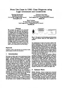
Figure 1. REBUILDER’s architecture.
Student
+ getTeacher(name: String) : Teacher
+ name : String
+ addStudent(name: String) : int + removeStudent(name: String) : int
adapt and revise software designs in the form of UML class diagrams. This system is briefly detailed in the next section. Section 3 describes what is a case in REBUILDER, and what the knowledge base used comprises. Section 4 describes the retrieval mechanism, showing how cases are retrieved and ranked. Two of the main reuse processes: analogy and design composition, are described in sections 5 and 6. Then section 7 describes the verification mechanisms responsible for detection of syntactic and semantic errors, section 8 presents some experimental results of diagram reuse, and section 9 concludes this paper.
2. REBUILDER The main goal of REBUILDER is to provide the software designer with a design environment capable of promoting software design reuse. CBR is used as the main reasoning process, and cases are the main knowledge source. It comprises four different modules: Knowledge Base (KB), UML Editor, KB Manager and CBR engine arranged in a client-server architecture (see figure 1). The KB used in REBUILDER comprises the WordNet server and the file server, while the clients comprise similar modules. The main difference between clients is that the manager client has an extra module allowing the KB maintenance. There can only be one server of each type, and only one manager client. Designer clients can be several depending on hardware resources. The UML editor is the front-end of REBUILDER for the software designer, and the environment where s/he develops the system’s designs. The KB Manager module is used by the administrator to manage the KB, keeping it consistent and updated. The CBR engine performs all the inference work in REBUILDER. It comprises five sub modules: retrieval, composition, analogy, verification, and learning.
1..*
+ studentID : int
+ getStudent(name: String) : Student
Figure 2. An example of a class diagram.
3. Knowledge Base The KB stores all the knowledge needed for REBUILDER’s reasoning mechanisms. It comprises a case library, the WordNet ontology, the case indexes and the data type taxonomy. We start this section with the case representation, and then with the description of the various sub modules of the KB. In REBUILDER a case describes a software design in UML, through the use of Class Diagrams (figure 2 presents a simple example). UML class diagram objects considered in REBUILDER are: packages, classes, interfaces and relations. A package is an UML object used to group other objects. A class describes an entity in UML and it corresponds to a concept described by attributes at a structural level, and by methods at a behavioral level. Interfaces only have method declarations, since they describe a protocol of communication for a specific class. Relations describes relationships between objects. WordNet [4] is used in REBUILDER as a common sense ontology. Symbols are words, and concept meanings are called synsets. A synset is a concept represented by one or more words. WordNet comprises a list of word synsets, and different semantic relations between synsets. The first part of WordNet is a list of words, each one with a list of synsets that the word can represent. The second part, is a set of semantic relations between synsets, like is-a relations, partof relations, and many other relations. In REBUILDER we use the word synset list and four semantic relation: is-a, part-of, substance-of, and member-of. REBUILDER uses synsets for categorization of software objects. Each object has a context synset which represents the object meaning. The object’s context synset can then be used for computing
object similarity (using the WordNet semantic relations), or it can be used as a case index, allowing the rapid access to objects with the same classification. Indexes provide a way to access the relevant case parts for retrieval without having to read all the case files from disk. Each object in a case is used as an index. REBUILDER uses the context synset of each object to index the case in WordNet. This way REBUILDER can retrieve a complete case, using the case root package, or it can retrieve only a subset of case objects, using the objects’ indexes. The data type taxonomy is a hierarchy of data types used in REBUILDER. Data types are used in the definition of attributes and methods. The data taxonomy is used to compute the conceptual distance between two data types.
4. Retrieval Retrieval in REBUILDER is a two stage process. First a set of relevant cases are retrieved from the case library using the indexing mechanism and WordNet. Then these cases are ranked by similarity degree with the target problem. The first phase is called case retrieval, the second one is called case selection or ranking. Case retrieval is based on the WordNet structure, which is used as an indexing structure. The retrieval algorithm uses the classifications of the target problem object as the initial search probe in WordNet. This algorithm is flexible enough to retrieve three different types of UML objects: packages, classes and interfaces, depending on the type of object selected as target problem. For example, if the designer selects a package as the target problem, the retrieval algorithm uses the package’s synset as the initial search probe. Then the algorithm checks if there are any packages indexes associated with the WordNet node of that synset. If there are enough indexes, the algorithm stops and returns them. Otherwise, it explores the synset nodes adjacent to the initial one, searching for package indexes until the number of found indexes reaches the number of objects that the user wants to be retrieved. We have defined three different versions of the retrieval algorithm. The first version is called the simple version, and is the one described before. The second version is called the extended version. The only difference is the initial search set of synsets, it comprises not only the package’s synset but also all the synsets of the objects in the package. The last version is called the ambiguous version, because it uses all the possible synsets of the package name (there is no disambiguation) as the initial search set. Section 8 describes some of the experimental results obtained with these algorithm versions. The second step of retrieval is ranking the retrieved objects by similarity with the target object. Since there are three types of target objects (packages, classes and inter-
faces) we have developed a specific similarity metric for each type of objects. The package similarity metric is based on four different aspects: the similarity between packages’ synsets, similarity between packages’ dependencies (dependencies are a type of UML relations that express object dependency), similarity between packages’ class diagrams, and similarity between the sub-packages (a recursive call to this metric). Basically this metric assesses structure similarity and semantic similarity of packages and its objects. The class similarity metric is based on three items: synset similarity of classes being compared, inter-class similarity comprising the assessment of relation similarity between classes, and intra-class similarity which evaluates the similarity between classes’ attribute and methods. The interface similarity metric is the same as the class similarity, except in the intra-class similarity, which is based only in method similarity, since interfaces do not have attributes.
5. Analogy Analogical reasoning is used in REBUILDER to suggest class diagrams to the designer, based on a query diagram. The analogy process has three steps: identifying candidate diagrams for analogy, which is done using the retrieval algorithm defined in the previous section; mapping the candidate diagrams; and creating new diagrams by knowledge transfer between the candidate diagram and the query. The second step of analogy is the mapping of each candidate to the query diagram, yielding an object list correspondence for each candidate. This phase relies on two alternative algorithms: one based on relation mapping, and the other on object mapping, but both return a list of mappings between objects. The relation-based algorithm uses the UML relations to establish the object mappings. It starts the mapping selecting a query relation based on an UML heuristic (independence measure), which selects the relation that connects the two most important diagram objects. The independence measure is an heuristic used to assign to each diagram object an independence value based on UML knowledge that reflects an object’s independence in relation to all the other diagram objects. Then it tries to find a matching relation on the candidate diagram. After it finds a match, it starts the mapping by the neighbor relations, spreading the mapping using the diagram relations. This algorithm maps objects in pairs corresponding to the relation’s objects. The object-based algorithm starts the mapping selecting the most independent query object, based on the UML independence heuristic. After finding the corresponding candidate object, it tries to map the neighbor objects of the query object, taking the object’s relations as constraints in the mapping.
The last step is the generation of new diagrams using the established mappings. For each mapping the analogy module creates a new diagram, which is a copy of the query diagram. Then, using the mappings between the query objects and the candidate objects, the algorithm transfers knowledge from the candidate diagram to the new diagram. This transfer has two steps: first there is an internal object transfer, and then an external object transfer. In the internal object transfer, the mapped query object gets all the attributes and methods from the candidate object that were not in the query object. This way, the query object is completed by the internal knowledge of the candidate object. The second step transfers neighbor objects and relations from the mapped candidate objects to the query objects, from the new diagram. This transfers new objects and relations to the new diagram, expanding it.
6. Design Composition The Design Composition module generates new diagrams by decomposition/composition of case diagrams. The input data used in the composition module is an UML class diagram, in the form of a package. This is the user’s query, which usually is a small class diagram in its early stage of development. The goal of the composition module is to generate new diagrams that have the query objects, thus providing an evolved version of the query diagram. Generation of a new UML design using case-based composition involves two main steps: retrieving cases from the case library to be used as knowledge sources, and using the retrieved cases (or parts of them) to build new UML diagrams. In the first phase, the selection of the cases to be used is performed using the retrieval algorithm described in section 4. The adaptation of the retrieved cases to the target problem is based on two different strategies: best case composition, and best complementary cases composition. In the best case composition, the adaptation module starts from the most similar case to the problem, mapping the case objects to the problem objects. The case mapped objects are copied to a new case. If this new case maps successfully all the problem objects, then the adaptation process ends. Otherwise it selects the retrieved case, which best complements the new case (in relation to the problem), and uses it to get the missing parts. This process continues while there are unmapped objects in the problem definition. Note that, if there are objects in the used case that are not in the problem, they can be transferred to the new case, generating new objects. The best complementary cases composition starts by matching each retrieved case to the problem, yielding a mapping between the case objects and the problem objects. This is used to determine the degree of problem coverage of each case, after which several sets of cases are constructed.
Table 1. Recall and precision values obtained for the retrieval algorithm configurations varying the retrieval set size. Recall
Precision
C1
C2
C3
C1
C2
C3
1
0.149
0.149
0.169
0.760
0.760
0.800
3
0.350
0.370
0.370
0.667
0.680
0.680
5
0.497
0.502
0.517
0.584
0.592
0.592
10
0.608
0.633
0.633
0.376
0.384
0.384
15
0.698
0.712
0.693
0.280
0.293
0.283
20
0.707
0.697
0.697
0.214
0.214
0.214
These sets are based on the combined coverage of the problem, with the goal of finding sets of cases that globally map all the problem objects. The best matching set is then used to generate a new case.
7. Verification The verification phase comprises checking the objects’ names, relations, attributes, and methods. It’s main purpose is to check the design coherence and correctness. The name checking is used whenever an object’s name is changed. The other verification procedures are used when a verify action is requested by the user. The verify action first checks the relations, attributes, methods, and sub-packages of the package being verified. The sub-package checking is a recursive call to the verify action. Name checking is based on WordNet. Basically it uses WordNet to see if the object’s name is one of the WordNet words. If the verification module finds no corresponding word, then the user is presented with two alternatives: the object’s name is changed by the user, or s/he can browse WordNet to find a suitable name. This way it is assured that the system can find a suitable set of synsets. Relation checking is based on WordNet, on the design cases, and on relation verification cases, which are cases describing successful and failure situations in checking a relation validity. Attribute checking and method checking are similar to relation checking.
8. Experiments This section describes some of the experimental work done with REBUILDER. The basic goal of the experiments was to evaluate three aspects of the reuse mechanism: retrieval, adaptation (analogy and design composition) and verification. The case library used comprises 60 cases describing software designs. These cases are from four different domains:
Table 2. Experimental results obtained from test users. Time
T.Objs
U.Cases
%M.Objs
%W.Objs
AN DC1
26.64 72.08
7.36 18.20
1 4.40
26.93 70.27
11.98 29.18
DC2
59.68
5.84
1.28
71.07
21.57
banking information systems, health information systems, educational institution information systems, and store information systems (grocery stores, video stores, and others). Each design comprises a package, with 5 to 20 classes (total number of classes in the knowledge base is 586). Each object has up to 20 attributes, and up to 20 methods. Twenty five problems were defined, each one having one package with several classes (between 3 and 5), which were related to each other by UML associations or generalizations. These problems are distributed by the four case domains. For each problem a relevant set of cases from the case library was defined. This is used in the comparison with the set of cases retrieved by REBUILDER, yielding the recall and precision of the retrieval and similarity mechanisms. For each problem REBUILDER retrieved a set of cases. The size of these sets was varied in order to study recall and precision values along different retrieval size sets. We have defined three configurations, one for each retrieval version: C1 - simple version, C2 - extended version, and C3 - ambiguous version. The retrieval set size values experimented are: 1, 3, 5, 10, 15, and 20. Table 1 presents the recall and precision values achieved for the 25 test problems. These experiments show that the versions of the retrieval algorithm do not have significant differences in performance. The best retrieval set size for this experiment is 5, this is the one that maximizes recall and precision values. To evaluate the adaptation performed on each problem, REBUILDER generated six solutions, one for each configuration. The problems and their respective solutions were then presented to the test users (software designers and software engineers) for evaluation. Six test users were inquired to evaluate the solutions, giving their evaluation about the number of objects that they considered inadequate or incorrectly defined, regarding the problem that it was supposed to solve. Most of the designers made this judgment based on what they would delete from the suggested solution in order to solve the presented problem. The results obtained are presented in table 2, where AN stands for analogy, DC1 for design composition best case composition, and DC2 for design composition best set of cases composition, values presented are the average values for the 25 problems. Time - is the average computation time (in seconds) for generating one solution. T.Objs - is the average number of trans-
ferred objects by solution. U.Cases - is the number of cases used for generating a solution. %M.Objs - is the percentage of objects mapped to problem objects. %W.Objs - is the number of objects in the solution considered wrong by users.
9. Conclusions One advantage of our approach is that it can learn new cases, thus it can evolve in time adapting to the designers needs. REBUILDER enables the reuse of knowledge within the software company, through the sharing of design knowledge. It offers different mechanisms for reuse and other cognitive abilities that are useful to the designer. Nevertheless, the designer has the decision of selecting which one to be used and when to be used. Another advantage is that it communicates with designers through a widespread software design language - UML - keeping the human designers from learning a new formalization language, more computer-like. Due to the prototype stage of our tool, some performance figures are not what is desirable for deployment in a operation environment, but this can be overcome by some optimization efforts of code and design of REBUILDER. One limitation of our approach is that it deals only with the design level. Future work will consist on integration of other software development levels in REBUILDER and thus in the reuse process, like system analysis and requirement elaboration, and code reuse also.
Acknowledgements This work was partially supported by POSI - Programa Operacional Sociedade de Informac¸a˜ o of Fundac¸a˜ o Portuguesa para a Ciˆencia e Tecnologia and European Union FEDER, under contract POSI/33399/SRI/2000, by program PRAXIS XXI.
References [1] A. Aamodt and E. Plaza. Case–based reasoning: Foundational issues, methodological variations, and system approaches. AI Communications, 7(1):39–59, 1994. [2] B. Coulange. Software Reuse. Springer Verlag, London, 1997. [3] J. Kolodner. Case-Based Reasoning. Morgan Kaufman, 1993. [4] G. Miller, R. Beckwith, C. Fellbaum, D. Gross, and K. J. Miller. Introduction to wordnet: an on-line lexical database. International Journal of Lexicography, 3(4):235 – 244, 1990. [5] J. Rumbaugh, I. Jacobson, and G. Booch. The Unified Modeling Language Reference Manual. Addison-Wesley, Reading, MA, 1998.