An ASM Semantics for UML Activity Diagrams Egon B¨orger1, Alessandra Cavarra2, and Elvinia Riccobene2 1
Dipartimento di Informatica - Universit` a di Pisa - C.so Italia, 40 - 50125 Pisa
[email protected] (currently visiting Microsoft Research, Redmond) 2 Dipartimento di Matematica e Informatica - Universit` a di Catania V.le A. Doria, 6 - 95125 Catania {cavarra, riccobene}@dmi.unict.it
Abstract. We provide a rigorous semantics for one of the central diagram types which are used in UML for the description of dynamical system behavior, namely activity diagrams. We resolve for these diagrams some of the ambiguities which arise from different interpretations of UML models. Since we phrase our definition in terms of Abstract State Machines, we define at the same time an interesting subclass of ASMs, offering the possibility to exploit the UML tool support for using these special ASMs in the practice of software design. We apply these Activity Diagram Machines for a succinct definition of the semantics of OCCAM.
1
Introduction
In [1] it is stated that “UML is more than just a graphical language. Rather, behind every part of its graphical notation there is a specification that provides a textual statement of the syntax and semantics of that building block”. Indeed the so called precise semantics of UML [14] gives an unambiguous textual definition of the syntax for UML notations, nevertheless it leaves the behavioral content of various UML constructs largely open. In this paper we concentrate upon one of the principal diagram types which are used in UML for the description of dynamical system behavior, namely activity diagrams, and provide a rigorous definition of their dynamics. Thereby we assign to such diagrams a precise meaning, i.e. semantical content in the traditional sense of the word. In doing this we resolve for activity diagrams some of the ambiguities which arise from possible different interpretation of UML models [6,5,7]. Through our definitions we also build a framework for rigorous description and analysis of other possible interpretations of the intuitions which underly UML concepts. We hope that this will contribute to their rational reconstruction and to the rational comparison of different implementations. Since we phrase our definition in terms of Abstract State Machines [8], we provide at the same time an interesting subclass of ASMs, namely Activity Diagram Machines, whose use in software design is supported by UML tools. T. Rus (Ed.): AMAST 2000, LNCS 1816, pp. 293–308, 2000. c Springer-Verlag Berlin Heidelberg 2000
294
2
Egon B¨ orger, Alessandra Cavarra, and Elvinia Riccobene
UML Notation for Activity Diagrams
An activity diagram is a flowchart which exhibits the flow of control between the sequential or concurrent activities of a computational process. UML activity diagrams commonly contain the following types of nodes (also called states) and arcs. Initial nodes, exactly one per diagram, for the default starting place. Final nodes indicate where the control flow terminates. Action nodes represent an atomic action to be performed in zero (“insignificant”) time. Atomic actions are considered not to be decomposable, their execution not to be interruptible. Multiple invocations of action nodes might be executed concurrently. Activity nodes represent a “nested state structure”, a flow of control made up of other activity and action states. Zooming into an activity state, one finds an entire activity diagram which is entered by entering its (unique) initial state. Activity states are decomposable, the computation associated to them is considered to take some time to complete and to be interruptible by the occurrence of (external or internal) events. Activity nodes can come with entry and exit actions to be performed on entering/leaving the node respectively. Transitions specify the path from one action or activity to the next. A transition can be labeled by an event (so called triggered transitions) and by a guard, indicating that the transition is supposed to fire only if the event occurs and the guard condition is met. In UML events are never associated to (arcs coming out from) action states. Branch nodes specify alternative paths and have one incoming transition and two or more outgoing ones. Each outgoing transition has an associated Boolean expression called guard. The guards are supposed to be mutually disjoint and to cover all the possible cases. Fork/Join bars split a single flow of control into two or more concurrent flows of control respectively synchronize two or more concurrent flows of control. In UML the coroutine condition is assumed whereby a) the number of flows that leave a fork must match the number of flows that enter its corresponding join (balancing property, see section 3.1), and b) parallel activities may communicate with each other by messages. These (pairs of) composite and concurrent fork/join bars in UML activity diagrams delimit the concurrent nodes, to be distinguished from the activity nodes which represent sequential composite nodes. Entering a concurrent node (state) means to activate all of its subdiagrams so that at each moment in each of these subdiagrams at least one state is active, until exiting the corresponding join becomes possible when and only if all subdiagram computations have been terminated. In this prose description of the principal UML activity diagram concepts we have deliberately left out the so called object flow facility in UML diagrams. This feature allows objects to appear as nodes which are connected by dependencies to activities or to transitions which may create, modify or destroy objects. The ASM definition in the next section for the behavioral meaning of UML activity diagrams captures this object flow facility automatically through the underlying notion of ASM state transformation. A similar remark applies to communication between concurrent agents.
An ASM Semantics for UML Activity Diagrams
3
295
ASM Models for UML Activity Diagrams
In this section we associate to each building block of the UML notation for activity diagrams an ASM which models the behavior of the UML construct. We first describe the node and subdiagram types occurring in UML activity diagrams and then assign execution rules to them. 3.1
Signature of ASM Activity Diagrams
The graphs of ASM activity diagrams are finite directed graphs whose nodes and arcs belong to abstract sets N ODE and ARC coming with auxiliary static functions which yield information on the components (nodes, arcs, subdiagrams). N ODE is partitioned into atomic and composite nodes. Atomic nodes are partitioned into action and branching nodes, composite nodes into (sequential) activity and concurrent nodes. Action nodes are of form node(in, A, out, isDynamic, dynArgs, dynM ult) (1) where the parameter in denotes the (unique) incoming arc, out the (unique) outgoing arc, A an atomic action (to be defined by a set of simultaneous ASM function updates), isDynamic if A may be executed dynMult times in parallel, each time with an argument Li from a set dynArgs of sequences of objects {L1 , . . . , Ln }. (1)
(2)
out1
(3)
cond1 in
A
entry
in
out
D exit
[event ] out
in cond
n
outn
Branching nodes are of form node(in, Cond, Out) (2) where in denotes the incoming arc, Cond a finite sequence of disjoint and exhaustive boolean expressions and Out a sequence (of same length as Cond) of outgoing arcs. J The initial node • and final nodes • are considered as special action nodes without parameter. For each type of node parameter we use a (static) function param which applied to nodes yields the parameter. For example in(node) yields the incoming arc of node, action(node) the atomic action A associated to an action node, etc. We often suppress parameters notationally. Activity nodes are of form node(in,entry,exit,D,out,[event],isDynamic,dynArgs, dynMult) (3) where in denotes the incoming arc, out the outgoing arc, entry, exit the entry/exit actions, D the associated activity (sub)diagram and [event] an [optional] event which serves to determine interrupts (if any) of executions of D; isDynamic, dynArgs and dynMult play the same role as for the action nodes. In accordance with [13] events are admitted to label the outgoing arc only of activity nodes and not of action nodes.
296
Egon B¨ orger, Alessandra Cavarra, and Elvinia Riccobene
DIAGRAM is an abstract set of activity diagrams, EV EN T an abstract set of diagram events. A monitored predicate occurred defined on EVENT indicates that and when an event happens. It is assumed that an occurring event is immediately taken into account and consumed. Since the computation in an activity node subdiagram can be interrupted at any moment by every event which is associated to a transition coming out from an enclosing diagram, we introduce a static function evQueue : DIAGRAM → EVENT∗ which yields for each diagram D the sequence of all highest (outermost) occurrences, in diagrams in which D is nested, of all events whose firing can cause the exit of D. If an event e occurs in the evQueue of different not nested diagrams, then only that occurrence of e will have effect that is associated to the diagram where the control lies. Apparently it is assumed in UML that at every moment for each active diagram at most one event in evQueue can occur. Concurrent nodes are of form node(in, D, out) (4) where the parameter in denotes the incoming arc, out the outgoing arc, D a sequence D1 , . . . , Dm of subdiagrams (not consisting of only initial or final nodes)1 . In (4) the upper synchronization bar is called fork, the lower one join. (4)
(5)
in
Dm
D1 out
In addition to the functions which yield node parameters we will use the following auxiliary functions on nodes, arcs and diagrams. The diagram to which an arc belongs is given by the function diagram : ARC → DIAGRAM. The arc outgoing from the initial node is given by initArc : DIAGRAM → ARC. The arcs incoming to a final node are provided by finalArc : DIAGRAM → ARC∗ . For an activity node subdiagram D the function event : DIAGRAM → EVENT ∪ {undef} yields the occurrence of an event (if it exists) which labels the transition coming out from that activity node. The arc which is labeled by such an event is provided by the function arc : EVENT ∪ {undef} → ARC. out(D) yields the outgoing arc of the activity node with subdiagram D. exit (D) yields the exit parameter defined on the activity node with subdiagram D. If D is the main diagram, exit (D) returns its exit action. The predicate exited (D) is true if the exit action associated to the diagram D has been performed. FinalNode(n,D) is true if n is a final node of D. The subdiagram associated to an activity node whose outgoing arc is labeled by the occurrence of an event is provided by diagram : EVENT → DIAGRAM. In connection with labeled transitions, we use the function guard, defined on ARC, which yields the guard condition labeling an arc. On “not labeled” arcs this guard has the constant value true (and is therefore notationally suppressed). 1
The initial (resp. final) node of the subdiagrams Di is considered to be represented by the fork (resp. join) bar.
An ASM Semantics for UML Activity Diagrams
297
The nesting structure of an ASM activity diagram is encoded in the following static functions: – upDgm : DIAGRAM −→ DIAGRAM ∪ {undef }, assigning to a diagram D1 its immediately enclosing diagram (if any). – chainDgm : DIAGRAM × DIAGRAM −→ DIAGRAM ∗ ∪ {undef } chainDgm(D1 , D2 ) = [T1 , . . . , Tn ] where n > 1∧ T1 = D1 ∧ Tn = D2 ∧ ∀i = 1 . . . n − 1, upDgm(Ti ) = Ti+1 chainDgm yields an empty sequence on each pair of diagrams D1 and D2 c2 ) to indicate the where D1 is not nested in D2 . We write chainDgm(D1 , D c right open sequence chainDgm(D1 , D2 ) = [T1 , . . . , Tn [, if it exists. We denote by ⊂ the transitive closure of upDgm, i.e. D ⊂ D0 iff upDgm(D) = D0 ∨ ∃D00 (upDgm(D) = D00 ∧ D00 ⊂ D0 ) Definition 1 (ASM Activity Diagrams). An activity diagram is defined recursively following its sequential depth, i.e. the maximum level of nesting of occurring activity nodes, and its concurrency depth, i.e. the maximum level of nesting of occurring concurrent nodes. – A sequential ASM activity diagram of sequential depth 0 is a finite directed graph containing only atomic nodes and exactly one initial node. – A sequential ASM activity diagram of sequential depth n + 1 is a finite directed graph containing besides atomic nodes only activity nodes whose associated subdiagram is an ASM activity diagram of sequential depth at most n. – Every sequential ASM activity diagram (i.e. of finite sequential depth) is an ASM activity diagram of concurrency depth 0. – An ASM activity diagram of concurrency depth n+1 is a finite directed graph D of atomic and composite nodes such that for each concurrent node which occurs in D or in a diagram of the D-subdiagram chain, its (immediate) subdiagrams are ASM activity diagrams of concurrency depth at most n. Any ASM activity diagram of arbitrary concurrency depth is called an ASM activity diagram. ASM activity diagrams of positive concurrency depth are called concurrent ASM activity diagrams. Remark 1. UML activity diagrams inherit through the metamodel in [14] all the features of state diagrams including synchronization nodes to synchronize concurrent subactivities. One transition connects the output of a fork in one flow to the input of the synch node, and another transition connects the output of the synch node to the input of a join in the other flow [12]. Synchronization nodes can be incorporated here by adapting the definitions given below for concurrent node synchronization.
298
3.2
Egon B¨ orger, Alessandra Cavarra, and Elvinia Riccobene
Rules of ASM Activity Diagrams
In this subsection we define the ASM rules which express the semantics of the control flow of sequential and concurrent activities as transformation of the configuration of the graphs of ASM activity diagrams. We use multi-agent ASMs [8] to model the concurrent subactivities in a UML activity diagram. ASMs are transition systems, their states are multi-sorted first-order structures, i.e. sets with relations and functions, where for technical convenience relations are considered as characteristic boolean-valued functions. The transition relation is specified by rules describing the modification of the functions from one state to the next, namely in the form of guarded updates (“rules”) if Condition then Updates where U pdates is a set of function updates f (t1 , . . . , tn ) := t, which are simultaneously executed when Condition is true. A multi-agent ASM is given by a set of (sequential) agents, each executing a program consisting of ASM transition rules. Distributed runs of multi-agent ASMs are defined in [8]. Let AGENT be the abstract set of agents a which move through their associated diagram diagram(active(a)) executing the activity required at the currently active arc of this diagram, i.e. the arc where the agent’s control lies. Thus active : AGENT → ARC is a dynamic function whose updates follow the control flow of the given activity diagram. The agents execute UML activity diagrams, i.e. they all use the ASM rules defined below. As a consequence we below use the 0-ary function Self which is interpreted by each agent a as a. We often notationally suppress Self, writing active for active(Self) and currDgm for diagram(active(Self)). Agents can be activated and deactivated during the execution. The current mode of an agent is recorded by a dynamic function mode : AGENT → {running, waiting, suspended, undef}. An agent can be running in normal mode, waiting for the end of concurrent subcomputations of his children—in these two cases we say that it is active—, suspended because exited from a sequence of nested diagrams when its computation has been stopped due to some event firing, or deleted (of mode undef ) when it has regularly finished its own computation. We formalize the data flow of activity diagrams by an env function representing the state of each agent. When an agent is created to perform a concurrent subcomputation (defined by one of the subdiagrams leaving from a fork synchronization bar of a concurrent node), he is linked to the parent agent by the dynamic function parent : AGENT → AGENT ∪ {undef}. We assume that this function yields undef for the main agent who is not part of any concurrent flow. The active subagents of an agent a are collected in the set SubAgent(a) = {a0 ∈ AGEN T | parent(a0 ) = a}. When an activity has to be performed several times in parallel, we “clone” the current running agent as often as required by the activity multiplicity. In order to distinguish the cloned agents from the original one, we introduce the predicate isClone on AGENT.
An ASM Semantics for UML Activity Diagrams
299
For the initial state it is required that there is a unique agent, in running mode with active arc positioned on the initial arc of the associated diagram DMain . In case the main diagram has an associated entry action we assume that this action has been executed as part of the initialization. 2 Typically a running agent, to determine the next action, has to look at the target of its currently active arc and to check that the associated guard is true and that no interrupt occurs. This is expressed by the following condition which appears as guard of most of the rules. currTarget is node ≡ mode(Self) = running ∧ noEventFor(Self) ∧ active(Self) = in(node) ∧ guard(active(Self)) where noEventFor(Self) ⇔ ∀e ∈ evQueue(currDgm) : ¬occurred(e). The semantics of atomic nodes is straightforward. By interpreting the UML concept of “atomic action” by “ASM rule”, we provide a rigorous semantical meaning to this concept which turned out to be general enough for contemporary system design [2]. If the control is on the arc in(node) and the associated guard is satisfied (in case of triggerless guarded actions or of transitions triggered by events which are classified as triggering internal transitions), then A is performed if the action node is not dynamic. Otherwise, if the number of the dynamic arguments dynArgs corresponds to the dynamic multiplicity dynMul, A is executed (by Self) concurrently on each argument list. The semantics of ASMs takes care of the consistency problem for the possibly conflicting concurrent updates of env, a problem which is hardly considered in [14]. In both cases, the control passes to the arc outgoing from the node. According to [14], if dynArgs is evaluated to the empty set, then no action is performed. If the dynArgs “evaluates to a set with fewer or more elements than the number allowed by the dynamic multiplicity . . . the behavior is not defined” [14]. This is reflected by the following rule Action Node. in
A
out
Rule Action Node if currTarget is node(in,A,out,isDynamic, dynArgs,dynMult) then if ¬ isDynamic then A elseif |dynArgs| = dynMult then forall Li ∈ dynArgs A(Li ) active := −→out
For action nodes without dynamic arguments standard ASMs guarantee A to be an atomic (indivisible) action. In the presence of dynamic arguments a concept of parameterized ASMs with atomic interpretation is needed as provided in [4] for structuring large machines. 2
The initialization could also be described by a rule which fires only in the initial state to perform the entry action of the main diagram DMain and to set the control of the unique running agent on the arc outgoing from the initial node.
300
Egon B¨ orger, Alessandra Cavarra, and Elvinia Riccobene
If the control is on the arc incoming to a branching node, the associated guard is satisfied and no interrupting event does occur, then the conditions are evaluated and the control passes to the arc associated to the true condition. out1 cond1 in cond
n
outn
Rule Branching Node if currTarget is node(in, (condi )i≤n , (outi )i≤n ) then if cond1 then active := −→out1 .. . elseif condn then active := −→outn
The way UML describes final nodes is ambiguous. One question is whether exit actions should be executed upon reaching final nodes (“normal” exit) or only when events occur which interrupt the subdiagram computation (“interrupt” exit). This is related to the question whether an arc is allowed to leave out of the subdiagram of an activity node(in, entry, exit, D, out, event) without passing through the out-arc of this node. The Normal Activity Exit rule defined below suggests one way of resolving this ambiguity, but others are possible. Semantics of an activity node. When an activity node is entered, its activity subdiagram is executed (once or multiple times in parallel, depending on the node dynamics) starting with the entry action and following the semantics of activity diagrams. The activity node is not exited unless a final node of the subdiagram is reached (normal exit) or trigger events occur on a transition coming out from it (interrupt exit). If the control is on the incoming arc of an activity node, the associated guard is satisfied and no interrupting event does occur, then the control passes to the initial arc of the nested diagram and the entry action3 is performed if the node is not dynamic. Otherwise, if the number of the dynamic arguments dynArgs corresponds to the dynamic multiplicity dynMult, D is executed in parallel on each argument list of the set dynArgs. The running agent Self is cloned dynArgs -1 many times. For each agent (a) the environment is extended by the corresponding dynamic list, (b) the control passes to the initial arc of the nested diagram and (c) the entry action is performed. (See the macro activate at the end of this section.) In [14] there is no mention what happens in case dynArgs is evaluated to the empty set. In our model no activity is performed and the agent waits on the incoming arc until a possible triggered event will put its control on the outgoing arc. If the value dynArgs differs from dynMult “the behavior is not defined” [14]. The rule Enter Activity does not fire in this case. If the control is on a final arc of the subdiagram of an activity node, two cases may occur, depending on whether the arc out outgoing from the activity node is labeled by an event or not. In the second case, the exit action must be performed. At the final arc of the main diagram the agent gets mode undef to stop the computation; otherwise, the control passes to the outgoing arc. All cloned agents end here their (concurrent sub)activities. (See the macro delete at 3
If not defined, entry stands for skip.
An ASM Semantics for UML Activity Diagrams
entry
in
D
[event ] out
exit
entry exit
[event ]
301
Rule Enter Activity if currTarget is node(in,entry,exit,D,out,[event], isDynamic,dynArgs,dynMult) then if ¬ isDynamic then active := initArc(D) entry else if |dynArgs| = dynMult then let dynArgs = {L0 , L1 , . . . , Ln } extend AGENT with a1 . . . an do forall 1 ≤ i ≤ n activate(ai , D, Li ) isClone(ai ) := true env := env ∪ L0 active := initArc(D) entry Rule Normal Activity Exit if currTarget is node & F inalN ode(node, currDgm) & event(currDgm) = undef then exit(currDgm) if currDgm = DM ain then mode(Self) := undef else if ¬ isClone(Self) then active := out(currDgm) else delete(Self)
the end of this section.) In the first case exit is possible only upon firing of the event. If an event ev occurs that is relevant for the current diagram, then first all exits from nested diagrams are performed, in the sequential order which is given by the subdiagram structure—this is achieved by iterating the ASM submachine exitDiagrams until its termination—and then the control passes to the arc labeled by ev. All cloned agents end here their own (concurrent sub)activities (rule Event Handling). Rule Event Handling if occurred(ev) & ev ∈ evQueue(currDgm) then seq InitializeExitDiagrams Iterate(exitDiagrams(ev)) if ¬ isClone(Self) then active := arc(ev) else delete(Self)
To perform the exit from nested diagrams in the order of the subdiagram structure one has to distinguish the following cases:
302
Egon B¨ orger, Alessandra Cavarra, and Elvinia Riccobene
1. The agent is inside a concurrent flow (i.e. parent(Self) 6= undef). The sequential execution order from children to parents for exiting subdiagrams is reflected by the check that all subagents have performed all their exit actions and that the agent’s current diagram is the next to be exited. If the event ev is significant only for this agent (i.e. it has no effect on the sibling agents participating in the concurrent computation), then all the exit actions from the current diagram to the diagram D = diagram(ev) associated to the event ev are performed. Otherwise, if the event has effect on all the sibling agents running in parallel, then all of them independently first perform all the exit actions from their own current diagram up to but excluding their 0 common ancestor diagram D = diagram(active(parent(Self))), and then set their mode to suspended whereby they stop their computation. 2. The agent is not inside a concurrent flow (i.e. parent(Self) = undef). If the agent is not parent of concurrent subagents and its current diagram is the next to be exited, then it performs in the correct order all the exit actions from its current diagram to the diagram D = diagram(ev) associated to ev. Otherwise, if the agent is parent of concurrent subagents, then it checks whether all subagents have concluded the exit actions of the diagrams under their control. In this case, the parent agent sequentially (a) performs in sequence all the exit actions from its current diagram to the diagram D = diagram(ev), and (b) gets mode running. To make this work we initialize the exiting submachine exitDiagrams by: InitializeExitDiagrams ≡ ∀D : exited(D) := f alse. The exiting submachine itself is defined as follows: exitDiagrams(ev) ≡ if parent(Self) 6=undef & ∀ a ∈ SubAgent(Self) : mode(a) = suspended & exited(currDgm) =false 0 then if upDgm(diagram(ev)) ⊂ D then exitFromTo(currDgm, D) 0 if upDgm(diagram(ev)) ⊇ D
c0 ) then seq exitFromTo(currDgm, D deactivate(Self) if parent(Self) = undef & exited(currDgm) =false then if mode( Self) = running then exitFromTo(currDgm, D) if mode(Self) = waiting & ∀ a ∈ SubAgent(Self) : mode(a) = suspended then seq exitFromTo(currDgm, D) mode(Self) := running where D = diagram(ev) 0 D = diagram(active(parent(Self)))
The macro exitFromTo(D1 , D2 ) performs sequentially the exit actions from the diagram D1 to the diagram D2 , following in this loop the subdiagram structure: exitFromTo(D1 , D2 ) ≡ loop through T ∈ chainDgm(D1 , D2 ) exit(T ) exited(T) := true
An ASM Semantics for UML Activity Diagrams
303
The macro deactivate(a) ≡ mode(a) := suspended stops an agent’s (sub)computation temporarily or permanently. The definition of sequential composition and of iteration of ASMs provided in [4] guarantees that the machine exitDiagrams starts in the state in which an event triggers the application of the Event Handling rule and terminates its execution before the next event may take effect, thus preventing nesting of calls of the exitDiagrams machine. Semantics of concurrent nodes. When the control is on an arc entering a fork synchronization bar, then the flow is split into two or more flows of control. The currently running agent creates the necessary new agents setting their mode to running. Each new subagent ai inherits the program for executing activity diagrams, its control is started on the first arc of its current diagram Di and its entry action (if present) is performed (see the macro activate below). The parent agent gets mode waiting and his control is moved to the arc outgoing from the join synchronization bar (see rule Fork below). When all the subagents running in a parallel flow reach their join synchronization bar, their parallel flows must be joined. The parent agent, who is positioned in waiting mode on the arc outgoing from the join bar, checks whether all his subagents have already finished their work. If yes, the parent agent gets mode running and deletes all the subagents (see rule Join below).
in
D1
Dm out
Rule Fork if currTarget is node(in, D1 , . . . , Dm , out) then extend AGENT with a1 . . . am do forall 1 ≤ i ≤ m activate(ai , Di ) parent(ai ) := Self mode(Self) := waiting active := out Rule Join if active = out(node(in, D1 , . . . , Dm , out))& mode(Self) = waiting & ∀ ai ∈ SubAgent(Self ) : mode(ai ) = running & active(ai ) = f inalArc(Di ) then do forall ai ∈ SubAgent(Self ) delete(ai ) mode(Self ) := running
304
Egon B¨ orger, Alessandra Cavarra, and Elvinia Riccobene activate(a,D,[S]) ≡ mode(a) := running Mod(a) := Mod(Self) env(a) := env(Self) [∪ S] active(a) := initArc(D) entry(D)
4
delete(a) ≡ mode(a) := undef Mod(a) := undef parent(a) := undef isClone(a) := false env(a) := undef active(a) := undef
Discussion
The activity diagram metamodel in [14] is a class diagram and thus provides only a structural, static definition without describing the control-flow semantics. Essentially it comes as a particular case of the state diagram metamodel although some state diagram features are meaningless for activities. For example stub states can never occur within an activity diagram due to the requirement [14] that an activity is always entered through its initial node and exited through a final node or by triggering of an event. Some features which appear in [14] but are not mentioned here are automatically covered by our definition. Namely call states are special action states and therefore require no separate formalization, similarly for synchronization nodes, which are variants of concurrent nodes, and for actions or activities which label transitions reflected by action and activity nodes targeted by the transition. The UML object and communication flow states are automatically captured in our model by the underlying notion of ASM state. We have resolved the ambiguity between admitting triggerless transitions within activity diagrams (as in [1]) and the requirement that a transition guard must be evaluated only after triggering the transition event, namely by assuming transitions to be optionally labeled by events and by interpreting empty transition guards as true. We have completed the definition of actions or activities where the list of dynArgs is empty. Our model provides a clear semantics of the object and communication flow within parallel and concurrent activities, although we did not commit to any specific reporting mechanism of subagents to their parents since [14] leaves this question open. On the basis of the ASM composition principles defined in [4] our model also resolves the issue of atomicity of exit actions, a problem which seems not to be addressed in [1,14].
5
Activity Diagrams for the Semantics of Occam
In this section we apply the ASM semantics of UML activity diagrams to give a rigorous but succinct formulation of the semantics of the programming language Occam [3], where the combination of rigor and succinctness is achieved by associating to the graphical UML notation a semantical ASM definition. The description starts from the usual graphical layout of a program as flowchart— we define below such a graph generation from programs—whereby the standard sequential and syntax directed part of control is already incorporated into the
An ASM Semantics for UML Activity Diagrams
305
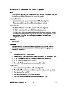
underlying graph structure (flattening the structured program) and thus semantically defined by the ASM rules for activity diagrams with atomic and concurrent nodes. It only remains to define the semantical meaning of the atomic actions—basic Occam instructions— which are executed by the agents when passing through the action nodes of the diagram. Figure 1 thus provides the complete definition of the semantics of Occam, where the atomic actions and the guards are specific for Occam and defined as follows. We use the function e to express the environment (i.e. the association of values to local variables) of each agent a and the function eval for expression evaluation under a given environment. s[v/t] denotes the result of substituting v in s by t (see Appendix for flowcharts generation from OCCAM programs).
stop:
skip:
bool: eval(b,e)
stop
skip
not eval(b,e)
com:
assign: assign(v,t)
c?v
writerAvailable(c)/
d!t
readerAvailable(d)/
alt:
par:
c 1? v 1 pass e
pass e
Dk
Dk
b: c 1? v 1
b: c k? vk c k? vk
collect e
Fig. 1. ASM Activity Diagrams for the Semantics of Occam writerAvailable(c) ≡ ∃ writer ∈ AGENT ∃n ∈ NODE: active(writer) = in(n) & action(n) = d!t & eval(c,e(a)) = eval(d,e(writer)) assign(v,t) ≡ e := e[v/eval(t, e)] pass e ≡ e(a) := e(parent(a)) collect e ≡ e(Self) := ∪1≤i≤k e(ai )
readerAvailable(d) ≡ ∃ reader ∈ AGENT ∃n ∈ NODE: active(reader) = in(n) & action(n) = c?v & eval(d,e(a)) = eval(c,e(reader))
c?v ≡ e(a) := e(a)[v/eval(t, e(writer for c))] d!t ≡ skip b:c?v ≡ writerAvailable(c)& eval(b,e(a))
In the Fork rule we add pass e to the updates of activate(a, D), in the Join rule collect e to the updates of Self. Occam syntax conditions guarantee that our definition of reader and writer for a channel is consistent, since for each channel at each moment at most one pair of reader/writer exists which are available for each other. Remark 2. The description in Figure 1 uses no composite activity nodes because we have assumed that in the initially given flowchart the structured
306
Egon B¨ orger, Alessandra Cavarra, and Elvinia Riccobene
parts of the underlying Occam program has been flattened. One can use activity nodes to describe such structural pieces of code directly, without flattening. Remark 3. The description of the ALT construct in Figure 1 really provides the deterministic Transputer implementation of this construct, due to the underlying UML assumption that the guards of branching nodes have to be evaluated in sequential order and to be disjoint and complete. One can reflect the non deterministic Occam interpretation of this construct by interpreting the guards gi as driven by monitored choice functions which directly reflect the non determinism, but outside the run. From the above definition of the semantics of Occam one can derive its implementation to Transputer code by a series of stepwise refinements of ASMs, see [3] where the correctness of such a transformation has been proved.
6
Conclusion
We have used ASMs to a transparent yet rigorous definition of the semantics of UML activity diagrams. Where the UML texts do not provide enough information to decide between different possible meanings, we have presented a formalization which seems to be in the main stream of the ideas surrounding UML. Exploiting the abstract nature of ASMs it is easy to adapt these definitions to changing requirements. We have applied Activity Diagram machines to provide a rigorous succinct definition of the semantics of OCCAM. We intend to use our notion of Activity Diagram Machines as a preparatory step for an ASM definition of UML state machines, declared in [10,9] to provide the official meaning of their implementation in Statemate.
References 1. G. Booch, J. Rumbaugh, I. Jacobson, The Unified Modeling Language User Guide, Addison Wesley, 1999. 2. E. B¨ orger, High Level System Design and Analysis using Abstract State Machines; in D. Hutter, W. Stephan, P. Traverso, M. Ullmann (eds): Current Trends in Applied Formal Methods (FM-Trends 98), Springer LNCS 1641, pp. 1–43, 1999. 3. B¨ orger E., Durdanovic I., Correctness of Compiling Occam to Transputer Code; in: The Computer Journal, Vol. 39, No.1, pp.52-92, 1996. 4. E. B¨ orger, J. Schmid, Composition and Submachine Concepts for Sequential ASMs. Gurevich Festschrift, Proc. CSL’2000 (to appear). 5. A. Evans, J-M. Bruel, R. France, K. Lano, B. Rumpe, Making UML Precise, OOPSLA’98 Workshop on “Formalizing UML. Why and How?” October 1998. 6. A. Evans, R. France, K. Lano, B. Rumpe, The UML as a formal modeling notation, UML98 - Beyond the notation, Springer LNCS, 1998. 7. R.B. France, A.S. Evans, K.C. Lano, and B. Rumpe, Developing the UML as a formal modeling notation; in Computer Standards and Interfaces: Special Issues on Formal Development Techniques, 1998. 8. Y. Gurevich, Evolving Algebras 1993: Lipari Guide; in E. B¨ orger (Ed.): Specification and Validation Methods, Oxford University Press, 1995.
An ASM Semantics for UML Activity Diagrams
307
9. D. Harel, A. Naamad, The STATEMATE Semantics of Statecharts, ACM Trans.Soft.Eng. method 5(4), 1996, 293-333. 10. D. Harel, M. Politi, Modeling Reactive Systems with Statecharts, McGraw-Hill, 1998. 11. Rational Software Corporation, Unified Modeling Language (UML), version 1.3, http://www.rational.com, 1999. 12. J. Rumbaugh, I. Jacobson, G. Booch, The Unified Modeling Language Reference Manual, Addison Wesley, 1999. 13. UML Notation Guide, 1999. (Published as part of [11]). 14. UML 1.3 Semantics, 1999. (Published as part of [11]).
7
Appendix
We here give a recursive definition for the generation of flowcharts from OCCAM programs. In this definition we make use of the following auxiliary functions: new(Domain) yields a fresh element from Domain makeLink(node,node0 ) yields node −→ node0 connect(−→,node) yields node label connect(node,−→) yields node makeLink(node,label) yields node g label connect(node,−→,g) yields node makeLink(label,node) yields node
−→ −→ −→
−→
−→
Definition 2. We define the function mkGraph(P,in,out) = cursion on the structure of the program P . Basis (Atomic program statements): - mkGraph(atomic,in,out) = mkGraph(c?v,in,out) = - mkGraph(d!t,in,out) =
atomic
in
in
c?v
in
d!t
out
in −→
P −→out by re-
atomic ∈ {assign(v, t), skip, stop}
readerAvailable(c)/ out
writerAvailable(d)/
Induction Step 1- mkGraph(P1 SEQ P2 ,in,out) = mkGraph(P1 ,in,mid) mkGraph(P2 ,mid,out) where mid = new(LINK)
3- mkGraph(WHILE b DO P,in,out) = let β = new(BRANCHNODE) yes = makeLink(β, b) return = makeLink(0 0 , b) connect(in,β) connect(β,out,¬b) mkGraph(P ,yes,return)
out
2- mkGraph(IF b THEN P ELSE Q,in,out) = let β = new(BRANCHNODE) yes = makeLink(β, b) no = makeLink(¬β, b) connect(in,β) mkGraph(P ,yes,out) mkGraph(Q,no,out) 4- mkGraph(PAR(P1 , . . . , Pk ),in,out) = let α = new(FORKNODE) αi = makeLink(α,0 0 ), i = 1,..,k β = new(JOINNODE) βi = new(ARC) connect(in,α) mkGraph(Pi ,αi ,βi ) connect(βi , β) connect(β,out)
308
Egon B¨ orger, Alessandra Cavarra, and Elvinia Riccobene
5- mkGraph(ALT(b1 : c1 ?v1 , . . . , bk : ck ?vk ),in,out1 , . . . , outk ) = let β = new(BRANCHNODE) li = makeLink(β, bi : ci ?vi ), i = 1,..,k connect(in,β) mkGraph(bi : ci ?vi , li ,outi ), i = 1,..,k 1-
2-
3-
4-
5out 1
in
c1? v1 b: c1? v1
b in
P1
mid
P2
P b
out
in
out ~b
Q
in
P
P1
Pk
~b out
in b:ck? vk ck? vk
out
out k