concern in integrated circuit (IC) chip manufacturing. The. Charge Oevice Model (COM) ESO stress is receiving increasingly more attention than the well-known ...
CDM ESD Failure Modes and VFTLP Testing for Protection Evaluation Yuanzhong (Paul) Zhou and Jean-Jacques Hajjar Analog Devices, 804 Woburn S1., Wilmington, MA 01887, USA Paul.Zhou @ analog.com
Abstract Most integrated circuit ESO damages are caused by COM stresses. This paper discusses COM failure modes. The most common such failure is damage to the gate oxide in the MOS device. A new methodology that uses a gate oxide damage monitor and modified VFfLP testing is proposed for assessing COM protection effectiveness and robustness in I/O circuits. A test structure for such an evaluation is also introduced.
1. INTRODUCTION Electrostatic discharge (ESO) is a major reliability concern in integrated circuit (IC) chip manufacturing. The Charge Oevice Model (COM) ESO stress is receiving increasingly more attention than the well-known and better controlled Human Body Model (HBM) stress in ESO design and testing. According to a recent survey [1], 99.9% ESO damages originate from COM mode failures. Two main factors contribute to this trend. One is the increased usage of automation in manufacturing and testing. The other one is the scaling of process feature sizes toward sub 100nm range. This makes modem devices more susceptible to the COM stress. COM simulates an ESO event that a charged IC part discharges when a pin contacts a grounded object or a conductive surface. The charge built-up in the IC die and package occurs through direct contact charging or field induced charging [2]. Current pulses in such an ESO event can reach several Amperes in magnitude in a few tenth of nano second. On the other hand, HBM simulates a discharge procedure where electrostatic charges transfer from a charged human body into a device directly through contact. The typical rise time is 5 to IOns and the pulse width is about lOOns. HBM has been the industry focus for a long period of time. A testing technique called Transmission Line Pulse (TLP) is a very effective tool to evaluate ESO robustness of a circuit or a single element for HBM stresses. A TLP tester applies a sequence of rectangular pulses between two terminals. Stablized voltage and current are recorded to represent the response of the device to ESO stress. A simple OC leakage between the two terminals is measured after each pulse to monitor the inception of device failure.
978-1-4244-2186-2/08/$25.00 ©2008 IEEE
TLP technology has been modified to target COM protection. It is called Very Fast TLP (VFfLP). It is consists of a shortened pulse . The pulse width is reduced from 75-200ns in standard TLP to I-IOns in VFfLP. However, due to different failure modes in COM and HBM, VFfLP for COM is not as effective as the TLP for HBM. In this paper, we will discuss the most common COM failure modes. A new evaluation methodology, as well as test structures, for CDM robustness assesment will then be proposed. In this new methodology, in addition to the leakage current monitor, threshold voltage and saturation current of MOS devices, which are more sensitive to gate oxide damages, will be used as device failure indicator.
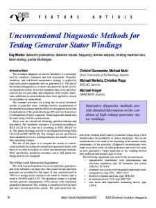
2. CDM FAILURE MODES The COM failure signature is damage to the gate oxide in MOS devices. This include oxide breakdown as well as latent oxide damage. Orain or source damages can also happen under COM ESO stress conditions. A pinhole in the gate oxide of an input receiver is a classic COM failure mode [3]. The damage is caused by the voltage across the gate oxide when a positive voltage is applied to the gate. The damage normally happens at the gate oxide over the source or the bulk. Gate oxide damage to output MOSFETs and grounded gate NMOS (ggNMOS) ESO devices have been reported [3,4]. The damage is caused by the voltage across the gate oxide when a positive voltage is applied to the drain. The damage normally happens at location where the gate oxide overlaps with the drain. The third type of COM failure occurs at the interface between power supply domains[5,6]. These are internal nodes that cross one power supply domain to another (see Fig. I below). These devices are not connected to any I/O pads. If the domains are resistively isolated from each other and low impedance ESO protection circuitry between them is missing or too resistive, the voltage differential may develop between the said two domains that exceeds the gate oxide breakdown and consequently damage core circuitry that is connected between the two domains in question. When power/supply domain areas are significantly different, COM damage is more likely happen in the smaller domains.
VDDI
Dnv~J
\lDD2
Rct>iver
~ ;i~IMe I I
VSSI
VSS2
Fig. 1 CDM failure at power domain interface Besides the three types mentioned above, CDM failures can also occur at internal circuit nodes inside a single power supply domain under certain special cases. One example is failure of internal gates driven by active circuits [7,8]. The internal gates can be damaged by the high voltage that develops at the output of the previous stage during a CDM event. For example, a receiver can get damaged when the driver circuit with a cascaded structure is activated during a CDM event. The power bus metal resistance was correlated to the failures. It was found that internal damages started to occur when the resistance reached a value greater than 1.5 Q [7]. Huh et al. [9] reported different internal damages from the one described by Brennan et al. [7]. The damage in a scan chain occurred in SOC designs with flip-chip package but not wire-bond packages. It was neither a power bus metal resistance induced failure nor a driver/receiver configuration related failure. It was found that the damaged internal circuits are always close to an I/O cell, which is called proximity effect. Long metal routing (> 1,200flm) between receiver and driver was found responsible for the failed nets. It is called long wire net effect. Another example is drain-source failures in PMOSINMOS stacks when the NMOS must be made larger than the PMOS. This is due to power supply overvoltage. When the power supply voltage reaches the combined snapback voltage of two devices, power density in PMOS is greater than in the NMOS since the PMOS has higher holding voltage and smaller size. Such CDM failures were observed in voltage level shifter circuits [7]. Gates tied to power supplies are exposed to the maximum VDD to ground voltage and may rupture in the case of over voltage [7]. MOS devices used as pull-up or pulldown resistors often have their gates connected to I/O power supplies: NMOS devices have gates connected to VDD and PMOS devices have gates connected to VSS. In CDM events, power supply network resistance has significant impact on ESD robustness, especially resistance associated with the VSS bus. There are also other damages to devices connected to chip pads, such as second breakdown in ggNMOS and
drain-source shorting in silicided output NMOS devices. Such damages are similar to the damages caused by HBM stress. The method commonly used to prevent CDM ESD damage on the gate oxide of an input receiver is a primary ESD protection element connected to the input pad, a secondary protection connected to the input receiver, and one resistor between the two ESD elements. To reduce failures on internal nodes, excessive wiring resistance should be avoided. ESD protection circuits are needed between power supply domains.
3. CDM PROTECTION EVALUATION 3.1 VFTLP for CDM Evaluation A CDM protection circuit should have the following two characteristics. First, it must be able to clamp the voltages between pads and within the internal nodes to a safe level. Second, it must respond to a given stress pulse fast enough to clamp the voltage in a timely manner. VFTLP can be a very useful tool for CDM protection evaluation if it is used properly. Unlike the CDM stress which stresses one termianl of the device after having charged it, VFTLP is a two terminal test. Nontheless it has adjustable (i.e. rise time, stress level, and pulse width) and relatively well defined wave forms. Moroever, it is very repeatable. This makes it an ideal tool to evaluate the effectiveness of CDM protection circuits. In standard VFTLP measuremnet a DC leakage measurement is performed after each pulse. This is used as a device failure monitor. Since ESD CDM damages are more likely to happen on the gate oxide of the protected device, this method is not effective in probing such device failures. The evaluation of CDM protection efficiency should focus on the protected devices and gate oxide damage. In light of this a new test methodology should be used.
3.2 Evaluation Structures with Fuses Staler et al. [10] developed three types of test structures for CDM effectiveness evaluation. Each structure consists of a protection element with a monitor element in parallel. NMOSFETs were used as gate monitors. Fig. 2 shows one example. The structures were tested by standard CDM testing in packages or using a package emulator. VFTLP stress was also used in this evaluation. The gate leakage current of the gate monitor was used as indicator of ESD failure. Staler et al. found the measurement of the gate leakage current challenging as it was usually smaller than the drain leakage of the ESD protection circuit. Consequently a fuse had to be introduced in the test circuit. The gate leakage current of the gate monitor was subsequently measured with fuse blown. On the other hand, comparing the gate
leakage before and after COM stress could not be performed. This was due to the existance of the fuse. --+-./+-I-....,------!L
~ /7 ~ fuse
II
pad
/,1
C v:
,
u..;
~
~ gate monitor
T
I
~_----,I
\tSS
Fig. 2 COM test structure with a fuse using MOSCAP as oxide monitor
3.3 New Evaluation Method and Structures Structures for COM evaluation should be consistent with the COM ESO failure modes described in previous sections. The impact of COM ESO stress must be easy to measure. The structures proposed by Staler et al. [10] are appropriate for such an evaluation since the stress effects were measured through the gate oxide monitor, instead of the whole OUT. Its shortcomings were that the leakage could not be record as a function of stress level on a single device. This significantly ·limits the efficiency of this method. We have developed a new method to improve COM ESO evaluation. It consists of making the following modifications to the existing techniques: 1) Add a third terminal to the VFfLP tester; 2) Use MOS transistors or CMOS inverters without fuses as the gate monitors; 3) Measure threshold voltage (Vth) or saturation current (Idd) of the monitor MOS transistors as the failure monitor. This method allows us to conveniently monitor device characteristics as function of ESO stress levels. Leakage current can be used as one supplemental failure indicator.
Fig. 3(b) shows another basic test structure that uses an inverter as the gate monitor. VFfLP pulses are applied between the terminals PAD and VSS or between PAO and VOO. Inverters are fundamental building blocks in IC circuits. Using inverters as the gate monitor can offer advantages that are convenient in characterization and better represent real world circuits.
4. EXAMPLES OF NEW METHOD Test structures were edesigned on an advanced 65nm CMOS process technology. The above described VFfLP testing has been carried out on different ESO protections. Figure 4 depicts the quasi-static I-V of an ESO protection using VFfLP test with rise time of lOOps and pulse width of 5ns. The protection consists of a ggNMOS as the primary element, a smaller off NMOS as a secondary protection and one resistor between the two ESO elements. A MOS device was used as the monitor. The data shows a failure at It2=8A. However, this point only indicated the failure of the protection device. 9,-----,-----.----.---.-------.-----.----.------,
8 7 6 __ 5 ~4
~
3 2 1
o -1 0
2
4
6
8 Vdut (V)
10
12
16
Fig. 4 I-V plot of a ggNMOS ESO protection with secondary protection by VFfLP 1
0.01 1e-04 1e-06
n
1e-08 1e-10
mowtor
g
j
m
-I
1----------------I1e-12 9 8 0.75
pad
Vth -----...--_.
~ 0.7
pad
> vss
Idd - -
(b)
Fig. 3 COM test structures using a MOS transistor (a) or an inverter (a) as oxide monitor The basic structure using MOS transistor as the gate monitor is shown in Fig. 3(a). No fuses are needed in the structures. VFfLP pulses are applied between the terminals PAO and VSS. The stress effects are evaluated through the gate oxide monitor by measuring the Vth and Idd of the monitor device using all three terminals.
7_ 6 ~
5:; 4:2
0.65 50
(a)
14
100
150
200
Vpulse (V)
Fig. 5 Vth, Idd, Ileak and Vdut vs. Vpulse for ESO protection with secondary protection The Vth and Idd of the monitor NMOS device measured at different stress voltages are shown in Fig. 5. The Vth and Idd indicate that the protected device failed at a much lower stress level than the breakdown shown in the I-V plot. Fig. 5 also shows the leakage current Ileak and the pad voltage Vdut as functions of stress voltages. Ileak varied over a wide range. Three major changes in
leakage may be observed in the figure. The last one at Vpulse=.215V is corresponding to the failure shown in the I-V plot in Fig. 4. Vth and Idd were almost constant before the monitor device was damaged. The damage of monitor was at the same stress voltage as the second major change in leakage. Fig. 6 shows the VFTLP snapback data of an LVSCR ESD protection device without secondary protection. Figure 7 gives the Vth and Idd of the NMOS monitor and the Ileak and Vdut of the whole DUT measured at different stress voltages. Though a major change in leakage was observed at Vpulse=.30V, Vth and Idd demonstrates that the failure of the ESD protection happened before the LVSCR entered snapback.
3r---------r--------r-----
2.5
2
'5
1
0.5
o -0.5 """--~-------------------J
o
2
4
6
8
10 12 14 16 18 20 Vdut (V)
Fig. 6 I-V plot of an LVSCR protection by VFTLP
............ ...... ......,
15
.;
.... ~""ff"""'~"
".
Pad Voltage
..••.•.•.•.
Leakage Current _ -
9
0.75
Vth
8
.
7 6 ~
Idd - -
~ 0.7 ~
:>
0.65 0.6
The most common CDM failure mode is damage to the gate oxide in MOS devices. A new methodology, as well as corresponding test structures, have been proposed to assess effectiveness of CDM protection circuits and CDM robustness of I/O circuits. The test structure consists of a protection circuit with a MOS transistor or an inverter in parallel as a gate oxide monitor. A modified VFTLP, with a third bias terminal added, is used to apply ESD stresses to the test structures and to allow DC chracterization on the monitor device. Threshold voltage Vth and saturation current Idd of the monitor device are used to evaluate the stress impact. Data measured on above structures showed the new method can overcome fundamental shortcoming in existing methods and provide effective assessment of ESD protection for CDM stresses.
REFERENCE
~1.5
!2
5. CONCLUSION
_ _--,-----J
~----=:::--~-----:,:,,--~
10
20
30
40
50
60
70
80
5
g
4
~
3 2
Vpulse (V)
Fig. 7 Vth, Idd, Ileak and Vdut vs. Vpulse for ESD protection of LVSCR Threshold voltage Vth of MOS devices is very sensitive to gate oxide degradation. Vth is a standard electrical test which is easy to measure. Saturation current Idd is another standard electrical test and is also easy to measure. As shown in the above two examples, measuring Vth and Idd of the monitor devices can catch the failures that may not be revealed by the leakage current. More significantly, the new method can trace the impact of ESD stresses as a function of stress level on a single device. Combining Vth, Idd and Ileak can provide a full picture of ESD failure, including both protected and protection parts. Threshold voltage shifts occur before actual oxide rupture. So it can detect latent oxide damages. Threshold voltage shift itself has significant impact to performance of analog circuits.
[1] R. J. Peirce, "The most common Causes of ESD damage", Evaluation Engineering, June 21,2004 [2] Steven Voldman., ESD: Circuits and Devices John Wiley and Sons, Ltd, 2006. ' [3] T. Maloney, "Designing MOS Inputs and Outputs to Avoid Oxide Failure in the Charged Device Model", Proc. EOS/ESD Symp., 1988, p220-227 [4] T. Brodbeck, H. Bauch, X. Guggenmos, R. Wagner, "Reproduccibility of Field Failures by ESD Models Comparison of HBM, Socketed CDM and Nonsocketed CDM", Microelectron. Reliability, Vol. 36, No. 11/12, 1996,pI719-1722 [5] E. Worley, "Distributed gate ESD network architecture for inter-power domain signals", Proc. EOS/ESD Symp., 2004, p239-247 [6] J. Lee, K. Kim, Y. Huh, P. Bendix, S. Kang, "ChipLevel Charged Device Modeling and Simulation in CMOS Integrated Circuits", IEEE Trans. Comput. Aided Design Integrat. Circuit Syst, Vol. 22, No.1, p67-80, (2003) [7] C. J. Brennan, J. Sloan, D. Picozzi, "CDM failure modes in a 130nm ASIC technology", Proc. EOS/ESD Symp., 2004, p182-186 [8] C. J. Brennan, J. Kozhaya, R. Proctor, J. Sloan, S. Chang, J. Sundquist, T. Lowe, D. Picozzi, "ESD Design Automation & Methodology to Prevent CDM Failures in 130 & 90nm ASIC Design Systems", J. of Electrostatics, Vo1.64, p 112-127 (2006) [9] Y. Huh, P. Bendix, K. Min, J-W Chen, R. Narayan, L. Johnson, S. Voldman, "ESD-induced Internal Core Device Failure: New Failure Models in System-onChip Designs", Proc. IDEAS'05 [10] W. Staler, et aI., "Test Circuits for Fast and Reliable Assessment of CDM Robustness of I/O Stages", Microelectronics Reliability, Vol. 45, No.2, p269-277 (2005)