Characteristic Modes Optimization Approach to Design a Wideband Electrically Small Antenna Hussein Jaafar, Sylvain Collardey, Dominique Lemur, Abdullah Haskou, Ala Sharaiha IETR UMR CNRS 6164- Université de Rennes 1, Rennes, France
[email protected],
[email protected],
[email protected],
[email protected],
[email protected] Abstract—A design methodology based on the combination of the Theory of Characteristic Modes (TCM) with an Optimization Algorithm, to design a wideband Electrically Small Antenna (ESA) is presented. Unlike other design techniques, loads or matching networks are not needed at the input of the antenna. A design example of an Inverted-L Antenna (ILA) is presented to validate the effectiveness of this technique. Index Terms—Antennas, characteristic modes, Differentrial Evolution (DE), Electrically Small Antenna (ESA), wide band antennas.
I.
be represented. The method is then verified on an Inverted L Antenna (ILA). II.
DESIGN METHODOLOGY
As stated in the introduction, the design procedure is based on the combination of the TCM, or more specifically the Network Characteristic Modes (NCM) with the DE algorithm. The aim is to find the optimal load value(s) at specified position(s) in order to match the antenna in a desired frequency range, while maintaining the simplicity of the design in terms of port numbers and the loading topology.
INTRODUCTION
The recent excessive need for miniaturization in wireless systems, implies the need for more compact electrically small antennas. Unfortunately, such antennas are limited in bandwidth as shown by Chu limit [1]. Several research works have then been focused on enhancing the bandwidth of Electrically Small Antennas (ESAs) through the use of wideband matching networks. However, these matching networks are constrained to the gain-bandwidth theory of Bode, Fano [2, 3]. To overcome such limitation and for a better performance, non-foster matching networks have been used as they are not imposed by the gain-bandwidth theory [4, 5]. More recent techniques have focused on using the aid of the Theory of Characteristic Modes (TCM) to obtain wideband ESAs, either by shape modification in order to control the resonance frequencies and the input impedance of specific modes [6], or by multiport loading in order to have a better control on the antenna’s current distribution over the desired frequency band [7, 8]. In [7] and [8], it was shown that the loads needed at each port to obtain a wideband antenna is a combination of Foster and Non-Foster reactive loads. However, the increased number of loaded ports in an antenna increases the complexity of the system, added to the complexity in the design of the required Non-Foster loads at each port. To eliminate these complexities, in this paper, we present a design methodology based on TCM combined with the Differential Evolution (DE) optimization algorithm, in order to design a multiport wideband antenna with the minimal number of required ports and simplest loading topology, without needing any loads at the input port. Hence, the design of a wideband ESA without an input matching network will
A. The Theory of Network Characteristic Modes Characteristic modes can be defined for multiport networks. These modes are expressed in terms of the N-port impedance matrix of the network, and can be computed from the generalized eigenvalue problem [9]: [𝑋𝑎 (𝜔)]Ῑ𝑛 (𝜔) = 𝜆𝑛 (𝜔)[𝑅𝑎 (𝜔)]Ῑ𝑛 (𝜔) (1) Where Ra(ω) and Xa(ω) are respectively the real and imaginary part of the N-port Z matrix at the radial frequency ω. Ῑn is the nth eigenvector (characteristic current) and λn is the corresponding eigenvalue. The total current at the radial frequency ω is then represented as a weighted summation of the characteristic currents given by the following equation [9]: Ῑ(ω) = ∑𝑁 𝑛=1 𝛼𝑛 (ω) Ῑ𝑛 (ω)
(2)
In a similar manner, the input admittance can be represented as a summation of the input admittances of each mode. The input admittance at a voltage gap located at the mth wire segment is given as follows [10]: 𝑌𝑖𝑛 [𝑚] = ∑𝑁 𝑛=1
Ῑ𝑛 [𝑚]2 1+𝜆𝑛 2
(1 − 𝑗𝜆𝑛 )
(3)
When adding loads to an N-port antenna, (1) becomes: [𝑋𝑎 (ω) + 𝑋𝐿 (ω)]Ῑ𝑛 (ω) = λ𝑛 (ω)[𝑅𝑎 (ω)]
(4)
Hence adding loads to the antenna will alter the eigenvalue problem, which implies altering the characteristic currents, their corresponding eigenvalues, and input admittances. The aim is to find a set of load(s) that can alter the input admittance in a way to match the antenna in a desired frequency range, this can be achieved by implementing the above equations in an optimization algorithm. B. Differential Evolution Algorithm DE have been widely used to solve electromagnetic problems [11, 12]. In [11], the authors combined NCM with DE algorithm, however this technique was applied on reactively controlled antenna array to find the optimal loading values on the parasitic elements at a single frequency, in order to control the radiation pattern at this frequency. In our case, we combine NCM with DE for a single multiport antenna, and try to find the optimal loading value(s) and topology, that can match the antenna in a wideband frequency range. Defining the objective function is a critical step to ensure the convergence of the algorithm towards our desired goals, here our objective function is very simple: (𝑘)
𝐹 = 𝐶𝑜𝑚𝑝𝑎𝑟𝑒𝑅𝑒𝑓𝑙𝑒𝑐𝑡𝑖𝑜𝑛(𝑆11 , 𝑆11𝑑𝑒𝑠𝑖𝑟𝑒𝑑 )
(5)
Where (𝑘) is the evolution generation index, 𝑆11 is a column vector containing the antenna’s reflection coefficient at each frequency point in the desired frequency range, 𝑆11𝑑𝑒𝑠𝑖𝑟𝑒𝑑 is the desired reflection coefficient for which 𝑆11 should be less than or equal, here it is considered -10 dB, CompareReflection is a function that compares each (𝑘) frequency point of 𝑆11 to 𝑆11𝑑𝑒𝑠𝑖𝑟𝑒𝑑 , and returns the number (𝑘)
of frequency points for which 𝑆11 is greater than 𝑆11𝑑𝑒𝑠𝑖𝑟𝑒𝑑 . (𝑘)
The algorithm converges when 𝑆11 ≤ 𝑆11𝑑𝑒𝑠𝑖𝑟𝑒𝑑 over the (𝑘)
whole frequency range i.e. all the elements of the vector 𝑆11 are less than −10𝑑𝐵 . Note that each element of the vector (𝑘) 𝑆11 is directly calculated from (3). (k)
S11 = 20log10 |
Y0 −Yin Y0 +Yin
|
eigenvectors. The behavior of the eigenvalues and eigenvectors is then optimized through loading using (4). Loads are optimized to manipulate the input admittances of the modes, such that the overall input admittance calculated from (3) yields a wideband antenna. However, before optimizing the loads, the loading topology should be initially specified. Specifying the loading topology offers simplicity in the design contrary to [7] and [8], where the loads are synthesized based on the behavior of the reactance as a function of frequency, which mostly results in a complex topology. III.
EXAMPLE: INVERTED L ANTENNA
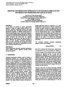
The method presented above can be applied on any antenna. Therefore, to verify this method we consider an ILA of dimensions 9.5 × 20.5 𝑚𝑚2 , integrated on a Printed Circuit Board (PCB) 90 × 35 𝑚𝑚2 , and printed on a 0.8mm Roger Duroid 5880 substrate (Fig.1). This antenna is excited at port 1, has a natural resonance frequency at 2.25 GHz, and a bandwidth of 175 MHz which is 6.5% of the center resonance frequency (Fig.2), in this paper, 𝑆11 < −10𝑑𝐵 is the criterion considered to define the antenna’s bandwidth. The goal is to match this antenna in a lower frequency band using just one loaded port, and hence obtain a wide band antenna with a reduced size factor. The desired frequency band is defined between 900MHz and 1.4GHz. After observing the surface current distribution of the first mode at 1GHz (Fig.3), we notice that the maximal current is mainly located in the first arm of the monopole, so the location of the loaded port is chosen as shown in (Fig.4). Note that in an N-port network, N characteristic modes are obtained from (1), hence in our case we have 2 characteristic modes, however, choosing the position of the load is more related to the first mode considering it is dominant in the desired range. 1
(6)
After briefly presenting the NCM and DE, in the next section we will explain the design methodology based on these two techniques. C. Optimisation process After specifying the antenna’s geometry and the desired frequency range in which the antenna should be matched, the positions of the input port and the loaded port(s) should be specified, note that the input port will not be loaded, hence the antenna will be matched without an input matching network. The position of the loaded port(s) is chosen where the antenna’s dominant mode exhibits a high surface current distribution, in the case of electrically small antennas, the dominant mode is the first mode. The Z matrices of the Nport network are then extracted over the desired frequency range using FEKO [13], to calculate the eigenvalues and
Fig. 1. Original ILA excited at port 1.
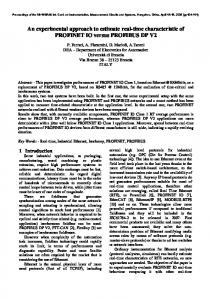
As shown in [7] and [8], the types of loads required to obtain a wideband antenna are mainly non-Foster loads, so to make the design as simple as possible, we chose the loading topology to be a simple capacitance. After running the optimization, the optimal load found to match the antenna in the required frequency band is a negative capacitance with value 𝐶 = −0.64 𝑝𝐹, which represents a non-Foster load. With this load, we were able to obtain a wideband antenna of bandwidth 582MHz, [947MHz-1529MHz], which represents 47% of the center frequency (Fig.5). Fig. 6 gives a more physical insight towards the obtained results, given the variation of the eigenvalue magnitudes of the antenna before and after loading, where the resonance frequency of the first
mode is shifted from 2.3GHz to a lower wideband frequency [947MHz-1529MHz], on the other hand, mode 2 is slightly affected by the loading.
Eigenvalue Magnitude(dB)
IV.
150
CONCLUSION
A design methodology based on the combination of NCM with DE is presented to widen an antenna’s bandwidth and reduce its size factor, without the need of an input matching network. This method offers a good trade-off between antenna’s performance and design simplicity. To demonstrate its effectiveness, this technique was applied on an ILA, resulting in a wideband electrically small antenna with a 47% bandwidth and size factor reduction of 44%. A prototype and its measurements will be submitted in the final version.
S11(dB)
-10
[5] 1.5 2 Frequency(GHz)
2.5
3
Fig. 2. Simulated reflection coefficient (dB).
[6]
1 [7]
[8]
Fig. 3. Surface current distribution of mode 1 at 1GHz.
1
[9]
2 [10]
[11]
[12]
Fig. 4. Unloaded 2-port ILA excited at port1. [13] [14]
0
S11(dB)
-5
-10
-15
-20 0
0.5
1
1.5 2 Frequency(GHz)
2.5
3
Fig. 5. Reflection coefficient of Loaded antenna (𝐶 = −0.64𝑝𝐹) at port 2.
0.5
1
1.5
2
2.5
3
REFERENCES [1]
[4]
1
0
Fig. 6. Eigen value spectrum before and after loading
[3]
0.5
50
Frequency(GHz)
-5
-15 0
100
-50 0
[2]
0
Mode1 Unloaded ILA Mode2 Unloaded ILA Mode1 Loaded ILA Mode2 Loaded ILA
L. J. Chu, "Physical limitations of omni-directional antennas," J. Appl.Phys., vol. 19, no. 12, pp. 1163–1175, Dec. 1948 H. W. Bode, Network Analysis and Feedback Amplifier Design. New York, NY, USA: Van Nostrand, 1945. R. M. Fano, "Theoretical limitations on the broadband matching of arbitrary impedances," J. Franklin Inst., vol. 249, pp. 139–154, 1950. James T. Aberle; Robert Loepsinger-Romak, "Antennas with NonFoster Matching Networks," in Antennas with Non-Foster Matching Networks , 1, Morgan & Claypool, 2007. A. Haskou, D. Lemur, S. Collardey and A. Sharaiha, "Miniature and wide-Band ILA Antenna with non-Foster matching," 2016 10th European Conference on Antennas and Propagation (EuCAP), Davos, 2016, pp. 1-3. J. J. Adams and J. T. Bernhard, "A Modal Approach to Tuning and Bandwidth Enhancement of an Electrically Small Antenna," in IEEE Transactions on Antennas and Propagation, vol. 59, no. 4, pp. 10851092, April 2011. K. A. Obeidat, B. D. Raines and R. G. Rojas, "Application of Characteristic Modes and Non-Foster Multiport Loading to the Design of Broadband Antennas," in IEEE Transactions on Antennas and Propagation, vol. 58, no. 1, pp. 203-207, Jan. 2010. E. A. Elghannai, B. D. Raines and R. G. Rojas, "Multiport Reactive Loading Matching Technique for Wide Band Antenna Applications Using the Theory of Characteristic Modes," in IEEE Transactions on Antennas and Propagation, vol. 63, no. 1, pp. 261-268, Jan. 2015. J. Mautz and R. Harrington, "Modal analysis of loaded N-port scatterers," in IEEE Transactions on Antennas and Propagation, vol. 21, no. 2, pp. 188-199, Mar 1973. A. Yee and R. Garbacz, "Self- and mutual-admittances of wire antennas in terms of characteristic modes," in IEEE Transactions on Antennas and Propagation, vol. 21, no. 6, pp. 868-871, Nov 1973. Y. Chen and C. F. Wang, "Synthesis of Reactively Controlled Antenna Arrays Using Characteristic Modes and DE Algorithm," in IEEE Antennas and Wireless Propagation Letters, vol. 11, no. , pp. 385-388, 2012. P. Rocca, G. Oliveri and A. Massa, "Differential Evolution as Applied to Electromagnetics," in IEEE Antennas and Propagation Magazine, vol. 53, no. 1, pp. 38-49, Feb. 2011. FEKO,Altair (www.feko.info) http://www1.icsi.berkeley.edu/~storn/code.html