can generate an Action Potential propagated throughout the axon till the axon terminal button, where the synapse, i.e. a junction, allows signal propagation to ...
1st IEEE International Workshop on Molecular and Nano Scale Communication (MoNaCom)
Characterization of signal propagation in neuronal systems for nanomachine-to-neurons communications Laura Galluccio, Sergio Palazzo, Giuseppe E. Santagati Dipartimento di Ingegneria Elettrica, Elettronica e Informatica (DIEEI) University of Catania (Italy) Email: {name.surname}@diit.unict.it Abstract— In the next decade nanocommunications will have great impact on biomedical engineering applications, for example in the view of allowing rehabilitation of patients which suffer for irreversible damage to the vertebral column. In such a case, the impossibility to move caused by an interruption in the propagation of nervous impulses, could be solved by exploiting nanomachines that employ the same communication paradigm of neurons to interact with them, thus allowing signal propagation across the body critical area. Accordingly, in this paper we perform a characterization and provide a model of the signal propagation between two entities which use a neuronal paradigm of communication, e.g. two neurons or a neuron and a nanomachine, so as to derive expressions of the transfer function, gain and delay incurred during the transmission. This could allow to design nanomachines compatible with the biological structures and able to integrate and substitute them when needed.
I. I NTRODUCTION Nanocommunications have been envisaged as a very pioneering communication paradigm which is deemed to provide significant advances to health care, biomedical as well as environmental and military applications [1]. However, whatever will be the system where nanomachines will be integrated, signal propagation should be characterized with high detail. In nanonetworks this task is difficult to be achieved since various communication paradigms have been discussed in the last years. Essentially, two classes of paradigms have been introduced: purely molecular and electromagnetic. Molecular communications [6] exploit chemical diffusion of particles and molecules as in living organisms while also performing coding and information transmission through chemical features. Different molecular communication ranges can be considered, as proposed in [1], [5]: short range communications (few nm to µm), where calcium signaling [12] or molecular motors [11] can be used to propagate information; medium range communications (µm to mm), where flagellated bacteria and catalytic nanomotors have been proposed as carriers [5]; long range communications (few mm) where pheromones, pollens and spores, as well as neurons, have been considered but no specific physical models have been proposed yet [13]. Electromagnetic communications, on the other hand, rely on use of appropriate transmitters and receivers [7], [16] as well as exploitation of carbon nanotube antennas [8], [10], [2] which are currently at an initial design stage. Also in this
978-1-4244-9920-5/11/$26.00 ©2011 IEEE
case much attention has been devoted to design RF circuitry to support such kind of communications and explore channel capacity [9]. In this paper we investigate a hybrid (molecular and electromagnetic) communication paradigm to characterize signal propagation in neuronal systems. To this purpose, molecular emissions, transduction and diffusion in a neuronto-neuron scenario are modeled. The system is decomposed into blocks, and delay and gains for each block are given as a function of the operating frequency. Moreover, frequencies at which the signal propagation could be effective are identified in the perspective of supporting the communication between nanomachines and neurons. The potentialities of this study are numerous especially in biomedical applications since in the next future nanomachines could allow the propagation of nervous impulses across body regions irreversibly damaged as a consequence of an accident or a disease (for example, an interruption along the vertebral column, Alzheimer, etc.). The rest of this paper is organized as follows. In Section II we describe the neuron structure. In Section III we provide a mathematical characterization of signal propagation in neuronal systems which is then used in Section IV to investigate on the neuronal system frequency behavior. Finally, in Section V, concluding remarks are drawn. II. N EURON STRUCTURE FOR EC ENGINEERS Target of this section is to describe how signals are transmitted in a biological nervous communication system with a language which can be easily understood by electrical and computer engineers. The nervous system is organized as a network of neurons. Each neuron receives inputs by a certain number N of other neurons and provides output to other M neurons1 . To this purpose, it is composed of dendrites which can be identified with the input interface, an axon used as the output interface, and a cell body, called soma, which implements the system logic2 . 1 Observe that, in general, neurons can receive input from and provide output to other cells besides neurons. We here do not consider this to keep our discussion easier. 2 There are different specialized types of neurons which can have slightly different structures but, in the rest of this paper, we will refer to the generic structure mentioned above.
437
A. Cellular membrane
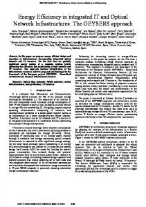
Fig. 1.
Neuron model.
The axon arises from the cell soma at the axon hillock characterized by a high concentration of ions channels. External signals reach the dendrites, propagate through the soma, and, once in the axon hillock, depending on the strength, can generate an Action Potential propagated throughout the axon till the axon terminal button, where the synapse, i.e. a junction, allows signal propagation to other cells.3 The axon can be up to one meter long (e.g. in the ischiatic nerve of human beings) and can be wrapped up by a myelin sheath used to shield the signal and allow propagation on a longer range; alternatively, the axon could be also unshielded and not wrapped by the myelin sheath. In case of nerve fibers, axon is always myelined to guarantee higher propagation speed and lower energy consumption. Observe that, due to the possible significant axon length, a high attenuation of the action potential while traveling along it could be met. To decrease the impact of channel attenuation in the axon, the myelin sheath is interrupted at some gap locations along the axon called Ranvier nodes. The typical size of these interruptions is around 1µm. Ranvier nodes are locations where electrical signals can be regenerated due to the high concentration of voltage-gated ion channels. Action potential is regenerated at these sites so that it finally comes at the axon terminal button. The result of the regeneration of the action potential at the Ranvier nodes is the, so called, saltatory conduction. Once the action potential reaches the axon button terminal it leads to neurotransmitters’ emission across the synapse that is the junction between a pair of neurons. At the postsynaptic element, binding between neurotransmitters and receptors implies generation of a synaptic current and, again, propagation of the action potential through a different neuron. The scheme of a generic neuron is shown in Fig. 1. In this paper we characterize how signals propagate from dendrites (i.e. input interface of the neuron) to the axon terminal button (output interface of the neuron); however, before describing such a system, we need to introduce some basics on general cellular structure. 3 Observe that two types of synapses exist: electrical (rarely) and chemical (more commonly). In the rest of this paper we will focus only on chemical synapses since they are the most widespread in biological creatures.
The cellular membrane is a fundamental element of all cells, including neurons. The membrane separates the internal cytoplasm from the extracellular medium. Distribution of ions4 in a cell is not at an equilibrium; in fact, there always exists a ion gradient which causes a diffusion process across the cellular membrane; this is fundamental for cells’ activity. As an example consider that typically there is an excess of sodium and chlorine ions Na+ and Cl− outside, and potassium ions K+ inside. This difference in ions’ concentration induces a voltage difference also when the cell is not hit by any stimula. This voltage difference is called resting potential. The ion gradient is maintained through an active transport system which continuously contrasts passive diffusion due to chemical equilibrium. Existence of stable ion gradient between the internal and external parts of a cell leads to a variation in membrane electrical potential. Membrane potential is the triggering element during nervous excitement since it allows the generation of electrical signals needed by neuronal communication. It is possible to efficiently modulate the membrane potential amplitude simply varying the membrane permeability to specific ions. Cell membrane consists of a phospholipid bilayer with embedded proteins able to perform basic functionalities for cell activity. The main membrane proteins can be classified as Membrane receptors, Ion channels and Ion pumps. Membrane receptors can bind only to certain molecules (called ligands), thus causing the activation of a specific biological or chemical effect. The membrane receptors involved in neuronal communications are placed in the dendrites and bind to certain proteins called neurotransmitters which are released in the synapse by the axon terminal button of a previous neuron. Ion channels form aqueous pores in the phospholipid bilayer that allow ions’ exchange through membrane. Obviously the voltage difference at the cellular membrane can be modulated by varying the number of open ion channels on the following of the binding between the receptors and the neurotransmitters due to the propagation of an action potential. Ion pumps carry ions against their concentration gradient using energy from ATP (Adenosine Triphosphate) hydrolysis and allow membrane active transport to maintain voltage difference at the cellular membrane. B. Action Potential When neurons are stimulated by external sources (e.g. during neuronal excitation), basically two types of responses take place: passive and active. Experimental tests show that, if electrical current flows through cell membrane, this reacts passively like a RC parallel circuit where R is the resistive component of ions’ transportation through ion channels at the membrane, and C represents the membrane capacitive component associated to the dielectric properties of the phospholipid bilayer.
438
4 Ions
are electrically charged particles.
In addition to a passive response, an excitable cell also exhibits an active response, called Action Potential or spike. If external stimulus is strong enough to make the membrane potential rise up to a threshold value, a depolarization occurs, and the response activates an all-or-none event in which the electrical membrane potential of a cell rapidly rises and then falls. The reason for this behavior is that when the sodium channels are open, they allow an incoming flow of sodium ions, which changes the electrochemical gradient; this in turn leads to a depolarization in the membrane potential which causes more sodium channels to open, producing a greater electric current. The process goes on until all the available sodium channels are open, causing a rise in the membrane potential. Due to the incoming flux of sodium ions, the membrane reverses its polarity and the ion channels then rapidly inactivate. When the sodium channels close, ions can no longer enter the neuron and are transported out the plasma membrane. Potassium channels are then activated so reporting the electrochemical gradient to the initial resting state. The Action Potential cannot be reinvoked immediately but there is an Absolute Refractory Period (ARP) that must elapse before a new Action Potential can be invoked due to the reactivation time in the ion channels. C. Synaptic transmission Transmission of electrical signals between excitable cells (e.g. neurons) takes place in specialized sites called synapses. Transmitter and receiver cells are defined as presynaptic and postsynaptic cells. Space between the two parts is called synaptic cleft. According to the communication strategy being used, we can classify synapse into electrical and chemical. The former allows direct communication between presynaptic and postsynaptic cells using electrical signals. The latter leads to a double signal transduction during transmission. Action potential generated by a presynaptic cell is transduced into a chemical signal, i.e. neurotransmitter concentration, which once reaches the postsynaptic cell, is re-transduced into a membrane potential. Neurotransmitters’ release in the synaptic cleft is caused by the Action Potential generated at the presynaptic cell, which forces neurotransmitter exocytosis from special containers called synaptic vesicles (see Fig. 1).
Fig. 2.
System building blocks.
it works and how it is characterized in term of input/output relationship, gain and delay. A. Presynaptic element The first block represents the presynaptic element of a chemical synapse. An information transduction is required in order to obtain a chemical signal from an electrical one. In detail, this block accepts as input a voltage value v and returns as output the concentration of neurotransmitters currently released T . We assume that the input/output relationship follows a Boltzmann distribution as in [4] T (v) = TM /[1 + e
−
v−Vp kp
]
(1)
where TM is the maximum neurotransmitters concentration that can be released, v is the presynaptic voltage or action potential at TX (i.e. input signal), Vp is called the half activation potential and kp is a slope factor. Observe that, due to the action potential mechanism, the neurotransmitters concentration in the time domain typically exhibits an impulsive rectangular behavior and can be modeled as [4] T (t) = TM · [u(t − t0 ) − u(t − t1 )]
(2)
where u(·) is the step function and t0 and t1 are the time instants when the neurotransmitters release starts and ends. Observe that, in the frequency domain, by using the Fourier transform [3], the normalized variation in the neurotransmitters concentration can be modeled as
III. M ODEL Our objective is to model signal propagation between two neurons. This communication system can be represented as shown in Fig. 2. In this figure two entities are depicted, TX and RX. In the rest of this paper we will model the blocks inside the dotted line which correspond to the condition when the signal enters the presynaptic element of the TX and then leaves the axon of the RX. As depicted in the scheme, this communication system can be considered as composed of different blocks; each of them properly models a phase in neuronal communication. In the following we will analyze in detail each block, describing how
H1 (f ) = sinc(f (t1 − t0 ))e−j2πf (t1 −t0 )
(3)
and the delay introduced is D1 (f ) = −dφH1 /df = 2π(t1 − t0 )
(4)
This output concentration is propagated through the synaptic cleft. Accordingly, a variation in the neurotransmitters concentration occurs as a function of the distance traveled in the cleft. In the following section, this diffusion through the synaptic cleft will be characterized.
439
B. Channel Usually the diffusion of the neurotransmitters across the synaptic cleft is not modeled [4] and the synaptic cleft is considered as a reliable channel which does neither attenuate nor introduce any delay in the signal propagation. Instead, an accurate characterization of signal propagation requires to consider also the neurotransmitters diffusion in the cleft. Accordingly, in this section, we recall the main aspects of the particle diffusion process described in [14] to model through a diffusive approach this propagation of neurotransmitters. Let us consider a concentration T of neurotransmitters which travel through the synaptic cleft, which size is dClef t . By using the diffusion theory [15], and, in particular, the second Fick’s law and the Telegraph equation [15], the concentration variation inside the cleft can be modeled using a normalized gain function as [14] R +∞ g(dClef t , t)e−j2πf t dt −∞ (5) H2 (f ) = R +∞ maxf ( −∞ g(dClef t , t)e−j2πf t dt) where g(·) is the impulse response of the system and can be written as [14] p 2 2 −t/(2τ ) cosh( t − (||x||/c) ) p g(dClef t , t) = e · u(t − ||x||/c) 2 2 t − (||x||/c) (6) being ||x|| the distance from the presynaptic terminal, c = p D/τ the wavefront speed, τ the relaxation time, D the diffusion coefficient, and u(·) the step function. The delay introduced by this block can be written as D2 (f ) = −dφH2 /df = −d(atan(
=(H2 (f )) ))/df