International Journal of Applied Information Systems (IJAIS) – ISSN : 2249-0868 Foundation of Computer Science FCS, New York, USA Volume 6– No. 7, January 2014 – www.ijais.org
Chef Alerting System using Wireless Zigbee Technology Sheifali Gupta1, Ph.D, Shivam Gupta2, Sourav Garg3, Nitin Goyal4,Sukhbeer Singh5 Department: Electronics and Communication, Chitkara University Chandigarh-Patiala National Highway, Dist.: Patiala, Punjab (India)
ABSTRACT
2. SOLUTION PROPOSED
This paper elucidates the concept and development of Zigbee technology which is IEEE standard 802.15.4 in dish ordering systems in hotels. This paper has shown the concept of an automatic self ordering system directly given to the chefs by the customer. The real time ordered data is send wirelessly using Zigbee technology. Chef can get the information simply on a display screen regarding dish name to be prepare and on which table it is ordered.
This paper presents with a solution to the hotel management for providing the fastest services to the customers. Since then we have two major problems. Firstly we have to increase range so we use Zigbee technology for the transmission purpose. Second is reducing the service time. This paper aims to show that managing queuing strategy that can solve this problem. This paper can help in making a restaurant fully automated. The waiter will take the orders from the customers table and ask for the confirmation of the order when the order is confirmed the order will be send to the concerned chef automatically through the wireless transmission by using Zigbee module. On the advancement this paper can became more reliable by using digital touchable screens given to the waiter or hardware is embedded over the table on which customer is sitting for giving the orders to the chef. The whole of the ordering, billing information can be send to the internet using LAN cable on the chef receiver side. This will help the higher management to get noticed about billing and each dish ordered. This will really help them during their auditing, and knowing there strength and weaknesses and also improvising on it.
Keywords Zigbee technology, chef Alerting System, advancements in hotel management, technology solutions for reducing service cycle timings in hotels, improving hotel management at low cost, wireless transmission using Zigbee, technology transfer in hotels
1. INTRODUCTION Today in this fast developing world hotels play a vital role in getting the tourist attraction. Today the customers in the hotels want hygienic food but above all a ‘quick service’. Time is important for all. Today numerous types of technologies are emerging for the different section of society but there are limited solutions being provided to the hotel industry. Restaurants would avoid losing their customers due to a long wait on the line. Some restaurants initially provide more waiting chairs than they actually need to put them in the safe side, and reducing the chairs as the time goes on safe space. However, waiting chairs alone would not solve a problem when customers withdraw and go to the competitor’s door; the service time may need to be improved. This shows a need of a model for the restaurant management to understand the situation better. Till now only manual waiters were there who take the order and forward that order to the inner kitchens of the hotel and then these orders were distributed to the chefs, which takes a lot of time, since the order given and reached to the chef and also when the chef prepared the order he then informs to the kitchen advisor and he informs back to the waiter. So in this whole process it takes a lot of time of the customer till the order given, to the order received. And today time is money. So this paper has come up with such a strong solution that maximum time of the customer can be saved and also the quality of service of the hotels is improved.
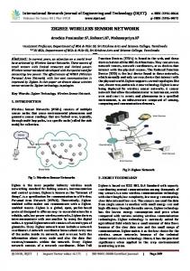
3. SYSTEM ARCHITECTURE AND DESIGN This paper is a whole automated system designed to get orders from the customers, make them ready and the delivered to them. The project has a system that is given to every waiter to take the orders. As the person takes the order and finalizes the dishes, the order number with dish codes are sent to the main chef automatically in the form of packets using a Zigbee wireless technology. The chef makes the dishes according to the order. When the dish will be ready the chef sends a ready command back to the waiter. There will be MCU (microcontroller unit) section to perform all the controlling of taking orders, sending it and receiving back the ready command. Order will be taken by using a matrix pad or by using digital touchable screen. Transmission is done by using Zigbee transceiver. The confirmed order is send to the internet by using LAN cable attached to the PC server.
Till now solutions proposed are only based on RF transmission which has the transmission range of that of only 4-5 meters that is why hotel authorities do not think this as a reliable solution to the problem. So we have to increase the range as well as reliability.
1
International Journal of Applied Information Systems (IJAIS) – ISSN : 2249-0868 Foundation of Computer Science FCS, New York, USA Volume 6– No. 7, January 2014 – www.ijais.org
Figure 1 :- chef alerting system transmitter(customer) This project can be used as a self service system which is working without the waiter. This project will be attached to the table on which the user is sitting he will give the order according to the need. This order will automatically send to the chef. When the chef will makes the order he will send ‘ready’ confirmation back to customer section that the order is ready and he can pick the order from the counter. This project eliminates the waiter that used to take the order and give it to the chef and takes order from the counter to the user.
Figure 3: Pin diagram(left) and Architecture(right) of 8051 Microcontroller 8051 has the following features: 1. 2. 3.
It has 4 Kb of ROM. It has 128bytes of RAM (including SFRs), satisfies the user's basic needs. It has 4 ports having in total of 32 input/output lines are in most cases sufficient to make all necessary connections to peripheral environment.
3.1.2 Zigbee RF Transmitter Receiver
Figure 2:- chef alerting system receiver
3.1 Hardware system design The proposed system hardware includes the following blocks:
3.1.1 Microcontroller: A microcontroller has a CPU (a microprocessor) in addition to the fixed amount of RAM, ROM, I/O ports, and timers are all embedded together on the same chip therefore, the designer cannot add any external memory, I/O, or timer to it. Microcontroller Unit is the heart of our project. It controls all the major activities of project. The Microcontroller unit used in the paper is AT89S52. Microcontroller is used for receiving input from switch pad, interpreting those signal, converting signal into packets and send it over the wireless connection through Zigbee and at the receiver side it convert packets into data and display that on the display unit and send it to the internet through LAN cable. (ref fig 3)
The CC2500 is a low-cost 2.4 GHz transceiver designed for very low-power wireless applications. The circuit is intended for the 2400-2483.5 MHz ISM (Industrial, Scientific and Medical) and SRD (Short Range Device) frequency band. The RF transceiver is integrated with a highly configurable baseband modem. The modem supports various modulation formats and has a configurable data rate up to 500 kbaud. CC2500 provides extensive hardware support for packet handling, data buffering, burst transmissions, clear channel assessment, link quality indication, and wake-on-radio. The main operating parameters and the 64- byte transmit/receive FIFOs of CC2500 can be controlled via an SPI interface. In a typical system, theCC2500 will be used together with a microcontroller and a few additional passive components. It has following features:
Low power consumption Integrated bit synchronizer Integrated IF and data filters. High sensitivity (type -104dBm) Programmable output power -20dBm~1dBm Operation temperature range : -40~+85 deg C Operation voltage: 1.8~3.6 Volts. Available frequency at : 2.4~2.483 GHz Digital RSSI
2
International Journal of Applied Information Systems (IJAIS) – ISSN : 2249-0868 Foundation of Computer Science FCS, New York, USA Volume 6– No. 7, January 2014 – www.ijais.org
3.1.5 Display Unit (Liquid Crystal Display) Display unit used in our project will be Liquid crystal display (LCD) which makes our project user friendly by displaying everything on the display. LCD can be used to display alphanumeric as well as special characters (like * @ ! # % & etc). This paper uses 16*2 LCD screen for displaying data. For connections of LCD (ref fig.7)
3.1.4 Buzzer Section
Figure 4:- Zigbee RF transceiver module 3.1.3 Switch pad A switch is an electrical component that can make or break an electrical circuit, interrupting the current or diverting it from one conductor to another. The paper has used the most familiar form of manually operated electromechanical switch with one or more sets of electrical contacts, which are connected to external circuits and. Each set of contacts can be in one of two states: either "closed" meaning the contacts are touching and electricity can flow between them, or "open", meaning the contacts are separated and the switch is nonconducting. This is a two terminal switch. Both terminals get shorted when it is pressed (i.e. in closed state) and both the terminals get disconnected when it is released (i.e. in open state). When the switch is pressed a low level signal is send to the pin of the microcontroller. This low level signal is due to the fact that one of the pin of switch is connected to the ground and other to the microcontroller. Default AT89S52 micro controller have high signal at its pins so to show any change we provide interrupt with low signal.
This section is used for the alerting purpose. A buzzer is used to produce beep sound. It is used to alert chef for the dish preparation and for customer to alert him about the dish ready signal. A small buzzer is used in this project which is easily available in the market. One of the pin of buzzer is connected to VCC pin and one pin is connected to the output pin of microcontroller (i.e. any port pin).
3.1.5 Designing Automated system to get orders from the customers, make them ready and the delivery of their orders. The project has a system that is given to every waiter to take the orders.
Figure 6:- Project Display
Figure 5: Switch Pad
3.1.4 Power supply Power supplies are designed to convert high voltage AC mains to a suitable low voltage supply for electronic circuits and other devices. A power supply can be broken down into a series of blocks, each of which performs a particular function. These functions includes stepping down (transformer), rectifying (using full wave rectifier), filtering (capacitor), and regulating (LM7805) in a manner of series of mentioning.
Designing of the system can be done by using following connections. RF transceiver is connected to the port3 with transmitter and receiver pin of CC2500 to pin 3.0 (serial transmitter) and pin 3.1(serial receiver) respectively of the microcontroller. LCD display is connected to the port 1 of the microcontroller section. RF transceiver is used as the interrupt and switch section is connected to the port 2 of the microcontroller. Switch pad are used in the polling method. Buzzer section is also connected to the pin 30 of the AT89S52 microcontroller. The other connections to the microcontroller AT89S52 are shown following diagram (ref fig7). The same Architecture is designed over the chef side but with some changes one is by attaching LAN wire to microcontroller and the other is that only one switch is required to send the confirmation for ready signal. There is a slight difference in the programming.
3
International Journal of Applied Information Systems (IJAIS) – ISSN : 2249-0868 Foundation of Computer Science FCS, New York, USA Volume 6– No. 7, January 2014 – www.ijais.org
Figure 7:- chef alerting system circuit diagram
3.2 Software system design Based on the flow chart in figure 5, firstly understand the concept of Zigbee technology and then do a research by collecting the data and information related to the “Chef alerting system using Zigbee System” based on the journal, books and internet sources. After that the drawing of the model project is sketched. Then, provide and built the hardware using the 8051 microcontroller, the Zigbee RF transceiver, the switch pad, the Microcontroller, the power supply and other components.[1] After completion developing the circuit, then troubleshoot is made by testing the circuit in order to know the circuit is work or not. Next, develop a programming by using Basic Compiler Programming in order to program the system of RF Zigbee in this project. In the programming section we have named each switch with a number using an enum function. Switch 1-4 are used for the dish number and switch 5 is used for the confirmation of dish and switch 6 for cancelling of dish. Switches 1-4 are the dish number which a customer wants to order. When any of these key is pressed then the system will ask for the confirmation of dish. If you are sure of order press button 5 and if you don’t want to order the dish press cancel button. When the confirm button is pressed then the same dish number and table number is send wirelessly to the chef through Zigbee module at the 9600 baud rate. ‘Order given’ will be displayed on the LCD. The chef is alerted using a buzzer sound and displaying the dish number to be prepared of particular table number on LCD. When the dish would be ready, by pressing the switch, chef will send the message back to the waiter that order is ready. For getting the programming implementation you can refer to flowchart (fig 9). Figure 8: flow chart for software implementation on customer side
4
International Journal of Applied Information Systems (IJAIS) – ISSN : 2249-0868 Foundation of Computer Science FCS, New York, USA Volume 6– No. 7, January 2014 – www.ijais.org
4. CONCLUSION AND FUTURE WORKS After completing this project, the objectives of this project were successfully accomplished on time. With this project, hopefully it can provide many benefits and gains to consumers where they can save time to users and ease of use and greatly helpful in the hotels. In conclusion, Zigbee based chef alerting system clearly shows improvements in the use and effectiveness as it is more systematic and effective than the existing manual ordering system. The middle man (waiter) is now removed by this project. User can give orders directly to the chef simply by using this project. In future this technology can be extended to the LAN connections by which the order information and calculation of bills can be send to the distance places to the owners of the hotels. The billing system can also be improved by using an ATM Swapping machine along with this project. The programming should be done in such manner that order can only be transfer to the chef if and only if the bill has been given.
5. ACKNOWLEDGMENTS
[2] 8051 Microcontroller: An Application Based Introduction by David Calcutt, Frederrick Cowan, and Hassan Parchizadeh [3] Keil website.[online].Available:www.keil.com/dd/ docs/datasheet “Atmel AT89S52 microcontroller datasheet” [4] M. Metev and V. P. Veiko, Laser Assisted Micro technology, 2nd edition ZIGBEE models based on new technologies [5] Low-Cost Low-Power 2.4 GHz RF “CC2500 Zigbee transceiver datasheet”
Transceiver
[6] S. Vijaya kumar, M.A. Shahid assisted “Menu Recommender to Enhance Customer Service and Improve Restaurant” (IJERT) Vol. 2 Issue 9, September 2013 [7] (2002) The IEEE website. [Online]. Available: http://www.ieee.org/ “PDCA12-70 data sheet,” Opto Speed SA, Mezzovico, Switzerland. [8] Interfacing “www.pantechsolutions.net/accessoryboards/zigbee-interfacing-with-8051”
Our thanks to all the experts who have contributed towards development of this paper
[9] ZigBee/IEEE 802.15.4 Summary Sinem Coleri Ergen email:
[email protected] September 10, 2004
6. REFERENCES
[10] R. E. Sorace, V. S. Reinhardt, and S. A. Vaughn, “Highspeed digital-to-RF converter,” U.S. Patent 5 668 842, Sept. 16, 1997S.
[1] Microcontrollers and Embedded System by Ali Mazidi
5