Key words: Business Process Modeling, Choreography, BPMN 2.0, Transforma- tion Rules .... and lower bands, respectively, of the participant tasks messageâexchanging rounded box. Thus ..... In BPMN 2.0 the intermediate event (timer) admits the definition of a ..... http://docs.oasis-open.org/wsbpel/2.0/wsbpel-v2.0.pdf. 12.
Choreography Modeling Compliance for Timed Business Models Manuel I. Capel1 and Luis E. Mendoza2 1
2
Software Engineering Department, College of Informatics and Telecommunications, University of Granada, 18071 Granada, Spain {manuelcapel}@ugr.es http://lsi.ugr.es/~ mcapel Processes and Systems Department Sim´ on Bol´ıvar University PO Box 89000, Caracas 1080-A, Venezuela {lmendoza}@usb.ve http://www.lisi.usb.ve/
Summary. Business Process Modeling (BPM) is a conceptual activity for embodying the functioning and complex structure of any enterprise’s business processes, so that these can be then analyzed and improved. A BP can be understood as a set of related, structured, interacting services driven by a choreography that is capable of giving complex functionality to customers. General choreographies of BP cannot be verified, specially timed choreographies, because implementations scarcely show the same behavior than the one initially specified according to business rules. We therefore propose here a formal semantics for a subset of BPMN, in order to check if a given choreography is realizable. This includes formalization of behavioral and temporal aspects of BPMN. A set of transformation rules for choreography diagrams into a timed process algebra is given. Therefore, we obtain an easy verification approach for choreography implementation models based on model–checking tools. In this way we can obtain advantage of the strengths that a formalization of behavioral and temporal aspects of BPMN will bring about, at design and implementation stages, to any model of interest. Key words: Business Process Modeling, Choreography, BPMN 2.0, Transformation Rules, Choreography Modeling Conformance, Timed Business Processes.
1 Introduction Business Process Model and Notation (BPMN) is now considered to be the standard modeling language for business process realm. BPMN uses a graphical notation, very similar to UML, and analogously to it their semantics is not formally defined. The referred models may lead to ambiguity and confusion with interpretation between technical and business users. Our proposal is mainly intended to propose a formal semantics to a set of BPMN modeling
Choreography Modeling Compliance for Timed Business Models
constructs, useful to enforce any choreography to be realizable; and then, it introduces an easy approach to the verification of business processes that may use model–checking techniques. Any choreography is said to be realizable if all the interactions specified in BPMN 2.0 diagrams are equivalent to those that can be executed with the analogous service–description language implementation, such as WS–CDL for instance. In a longer term perspective, we also aspire to support business analysts and modelers to find a way to improve the quality of their business models. Several authors have made progress in solving the choreography realization problem. The research work up until now can be divided into two categories, the first one focuses on business process model analysis, whereas the second one centres on obtaining a formal semantics of BPMN modeling entities. The main approaches of work in the first area can be found in [1] The principal challenge to this path of research is related with the necessity of transforming BPMN models into executable environments. Any BPMN transformation is more than just converting these models. We will not get significant results in improving BP models if task execution order and other influential elements from the environment are not considered during the analysis. With regard to the second group, there are formal methods proposed for verifying BPMN models based on Π-calculus [10] or Petri Nets [4], which can debug grammatical errors and can transform business processes diagrams (BPD) into BP Execution Language (BPEL) code [2, 11]. In this second group, the central problem to tackle consists of proving the soundness of BPMN model transformation. In many cases, a model cannot be verified because its representation in an executable environment does not show the same behavior as observed in the original model,i.e., it does not react to external events in the same way. The lack of verification exhibited by the aforementioned approaches, in our opinion, it is mainly due to semantic and syntactic problems caused by incorrect integration of (1)business properties formalization and (2)the corresponding BP–task model. We therefore propose here, (a)a set of transformation rules from a subset of BPMN temporal analysis constructs into Communicating Sequential Processes+Time (CSP+T) calculus, (b)an easy verification approach for task models designed with BPMN. Differently from other authors [17, 5], our method intends to merge the verification process of dynamic properties described by a choreography specification with the design of any BP model. In this way, we can take full advantage of the strengths that a formalization of behavioral and temporal aspects of BPMN models can provide to the analysis, both at design and run–time. Moreover, our aim is to facilitate the description of a BP model as a collection of verified software components, thereby allowing their complete verification with state–of–the–art model checking tools.
Choreography Modeling Compliance for Timed Business Models
2 BPMN Choreographies Formalization Business Process Model and Notation (BPMN) [12] is a standardized graphical notation that provides modeling elements for Business Process (BP) description with an emphasis on control–flow. A Business Process Diagram (BPD) is a specific type of flowchart that incorporates graphical constructs tailored to model BPMN elements, such as: (a)gateways, (b) events start, stop, (c)tasks, and (d)control flows. A BPD is easy to use and understand by non–technical personnel, usually management–oriented, for modeling BPs. Notwithstanding, a BPD offers the expressiveness necessary to model very complex BPs and it can be mapped to different business execution languages such as BPEL [2] or XLANG [19]. Figure 1 shows the main BPMN elements as they are represented in diagrams.
Fig. 1. Graphical representation of BPMN elements.
BPMN is a standard for the semi–formal specification of task workflows in business BP models and for describing the collaboration between services. BPMN 1.x only supported choreographic specifications through UML–like collaborative diagrams. The description of conversations between models’ components was considered to suit better the low–level services languages such as WS–BPEL. However, “interaction–based” business models consider the description of “conversations” between peers as the basic building blocks of any BP system design, whereas the specification of interfaces has become secondary to the system’s properties analysis. BPMN 2.0 supports now the collaboration between analysis entities in BP models, which brings forward a choreographic model based on peer interactions [16], instead of following a design model based on services orchestration [13]. BPMN 2.0 promotes a collaborative and abstract description of software systems that allows for focusing more on what services do in a composition than on how they do it. Interactions between system’s components or peers should be more precisely described now than in “interconnected interface” models, within which the interactions are defined internally to each peer only. BPMN 2.0 advocates for the Web Service Choreography Description Language (WS–CDL), which better fulfills the requirements of choreography specifications due to their global perspective of the system. Interactions between peers
Choreography Modeling Compliance for Timed Business Models
A
A
A
A
B
B
B
Choreog. task name
B
Fig. 2. Choreography diagrams.
are the basic building blocks of any WS–CDL specification, thus promoting the separation of concerns principle of Software Engineering. BPMN 2.0 Choreography Diagrams (BPMN-CD) describe one–way and two–way interactions between peers. In figure 2, the peers A and B are represented by the upper and lower bands, respectively, of the participant tasks message–exchanging rounded box. Thus, there is a two way interaction described: peer A receives a message and peer B sends a return message. Tasks on the right of the above one include internal markers, such as the standard loop (the interaction is performed several times depending on a boolean condition), multi–instance parallel loops (the interactions are performed by several instances of the choreography task), which can execute the actions in parallelk | or sequentially ≡. 2.1 Notation Formalization The elements of our core subset of BPMN can either be: tasks, subprocesses, multiple instances, pools, or control gateways. These notational elements represent states and are linked by Sequence, Exception or Message flows. A sequence flow is used to show the order that BP states are achieved. Exception flows deal with events that occurs during a BP execution and redirects the normal flow. Message flows represent the communication between two asynchronous modeling elements in a BPD, usually BP–participants, which are prepared to send and receive messages. A BP flow is depicted by modeling the Events that occur to start the BP, the activities that are carried out inside the BP, and the outcome of the BP flow. In figure 1, tasks are the lowest abstraction level components of a BP, i.e., any Activity that is not further decomposable into parts is considered a Task. Furthermore, an Activity in the flow can be considered a Subprocess, and thus graphically represented by another BPD connected via a hyperlink to a process symbol. Each task or subprocess can define multiple instances. Serial and parallel multiple instances are represented by specific state types in BPMN: miseq and mipar, which are meant to define a specific task repeated in sequence or composed in parallel, respectively. A Pool typically represents an organization or business entity and a Lane represents a department or a business worker within that organization, or other modeling entities like functions, applications, and systems. Both, pools and lanes, represent BP participants. Business decisions and flow branching are modelled using Gateways, which are
Choreography Modeling Compliance for Timed Business Models
similar to a decision symbol in a flowchart. The gateways are used to control how sequence flow interacts, by diverging and converging within a BP, and can define all the types of BP sequence flow behavior: branching (exclusive, inclusive, and complex decisions), merging, forking, and joining. 2.2 Denotational Semantics The abstract syntax of a significative subset of BPMN using Z schemas and the set theory can be summarized as it follows: Basic types = b [CName, P Name, Task , Line, Channel , Guard , Message] Subtypes = b [BName, PlName, InMsg, OutMsg, EndMsg, LastMsg] InMsg, OutMsg, EndMsg, LastMsg : P Message BName, PlName, PName : P Name Type : pgate | xgate | ogate | start | end hhNii | aborthhNii | task hhTask ii | link hhPNameii | bpmnhhBNameii | pool hhPlNameii | miseqhhTask × Nii | miseqshhBName × Nii | mipar hhTask × Nii | miparshhBName × Nii
Each BPMN entity ( [20]) has associated attributes describing its properties; for example the number of loops of a sequence multiple instance is recorded by the natural number in the constructor miseq. The type of a sequence flow or an exception flow is given by the following schema definition: Transition = b [guard : Guard ; line : Line]
and the type of message flow: Message flow = b [message : Message; channel : Channel ]
If the sequence flow has no guard or the message flow contains an empty message, then the values of Transition and Message flow record the default values “tt ” and empty respectively. There are five sets of message flows (send, receive, reply, accept, break ) associated to the state entity, which are syntactically defined in the next type and whose function follows from their names, State = b [type : Type; in, out, error : P Transition; exit : P(N × Transition); send , receive, reply, accept, break : P Message flow ; link : P(Transition× Message flow ); depend : P(Message flow × Message flow ); loopMax : N]
Each state also incorporates the variable loopMax to limit the number of state instances that each process can invoke. The state’s component link pairs the incoming message flow which initiates or interrupts the execution of the state with either an incoming transition or an exception flow. The component depend pairs each incoming message that initializes the state’s execution with its corresponding outgoing message flow.
Choreography Modeling Compliance for Timed Business Models
The formal semantics of BPMN abstracts (partial function hide) the internal flow of the modeling entity named state and only describes the sequence of initializations and terminations with the semantic function bpmn. [bpmn] bpmn : P Name → 7 Local → 7 Process hide : P Name → 7 Local → 7 P Event function name = (Y | [αY ]X )\hide(| S |)) Where X = ✷i : αY \hide(fin, abt ) • (i → X ✷ fin → null ✷ abt → stop) And Y = (ki : Process set • α(Pi ) ◦ P (i)) The partial function bpmn maps a syntactic description of a BPMN diagram encapsulated by a pool or BPMN–subprocess into a parallel composition of CSP+T subprocesses, which correspond to the diagrams of the basic elements of BPMN shown in Figure 2. The set αY represents the communication alphabet that includes all the messages types and events that may affect the execution of processes. These communications represent the events that a process P receives from its environment (made up of all the other processes in the system) or those events that occur internally, i.e., those which are not externally visible.
Fig. 3. Example of a BPMN diagram.
2.3 Example Consider, for instance, the simple example of an Hospital Pharmacy logistic process shown in Figure 3. The BPD depicts the message flows between two participants, the Ward and the Pharmacy, which are independent BP and may have been constructed separately. Clearly, the synchronization between both participants is a necessary behavioral property for successful collaboration. For example, from the pharmacy participant’s perspective, drugs delivering can be guaranteed by receiving a message from the ward participant prior a purchase order would be made or sent. From the ward participant’s perspective, to be sure to have the required drugs to begin a medical treatment, a
Choreography Modeling Compliance for Timed Business Models
message to the pharmacy participant, with enough time in advance, must be sent. The graphical description should describe the interaction between the peers(customer, ward, pharmacy, db) translated from the Hospital Pharmacy BPD shown in Figure 3, which represent the behavior of tasks within the pools Ward and Pharmacy. In this specification, we can firstly see that the customer interacts with the ward (demand for drugs), then sends the prescription to the pharmacy (search drugs) and eventually receives a response if the drug is in stock. On the contrary, the pharmacy makes an order (purchase order) and when the drug is available, it delivers the drug to the ward, which goes into (receive drugs) state. In either case, the prescription will be prepared and given to the customer to (start medical treatment), thereby terminating the complete protocol.
3 CSP+T CSP+T [21] is a real–time specification language which extends Communicating Sequential Processes (CSP) allowing the description of complex event timings, within a single sequential process, for use in the behavioral specification. The CSP+T language is defined by the rules, SKIP STOP ta .a → P e t0.⋆ → P ta .a ✶ v → P P #Q P ⊓Q P ✷Q P \A P △Q I(T , t1 ).a → P
:≡ :≡ :≡ :≡ :≡ :≡ :≡ :≡ :≡ :≡ :≡
e I(T , t1 ) → P P kQ P | [A] | Q
:≡ :≡ :≡
P 9Q :≡ I(Ta , ta ).a → P | [A] | :≡ I(Tb , tb ).b → Q
µX • P ✷m i=1 : N • P (i ) d m i=1 : N • P (i ) gm fmi=1 : N • P (i ) i=1 [A] : N • P (i ) fm i=1 : N • A(i ) ◦ P (i )
:≡ :≡ :≡ :≡ :≡ :≡
success (successful termination) deadlock a occurs at ta , then P (prefix) e (⋆ ∧ s(⋆) = t0) then P(instant.) (ta .a ∧ s(a) = ta ) then P (marker ) P (successfully) followed by Q P or Q (non–deterministic) P choice Q (external choice) P without A (hiding operator) P interrupted by Q (ta .a ∧ ta ∈ [rel (t1 , v ), rel (t1 + T , v )]) then P (event–enabling interval) e (delay of T) t > rel (t1 + T , v ) then P P in parallel with Q (composition) P in parallel with Q in alphabet A (alphabetized composition) P interleave Q (interleaving) P kQ if (a = b) ∧ (I(Ta , ta ) ∩ I(Tb , tb ) 6= ∅) P 9 Q if (a 6= b) ∧ (I(Ta , ta ) ∩ I(Tb , tb ) 6= ∅) STOP if I(Ta , ta ) ∩ I(Tb , tb ) = ∅ the process X such that X = P (X ) i : N → P (i ) (external choice) P ((τ −)action) (internal choice) g i : N → fm i=1 P (i ) (indexed) i : N → fm i=1 P (i ) (partial) i :N → m i=1 A(i ) ◦ P (i ) (parallel combination of processes)
(1)
Choreography Modeling Compliance for Timed Business Models
A CSP+T process term P is defined as a tuple (αP , P ), where αP = is the communication alphabet of P . CSP+T is a superset of CSP, the latter being changed by the fact that traces of events become pairs denoted as t .a, where t is the time at which event a is observed. Given the communication alphabet Σ, M a set of marker variables, T a set of times instants, I a set of time intervals, P a set of process names, and the function s(ta .a) that returns the time at which symbol a occurs. The event enabling interval I(T , ta ) = {t ∈ T | rel (ta , v ) ≤ t ≤ rel (ta + T , v )} indicates the time span where any event is accepted. rel (x , v ) = x + v − t0 , t0 corresponds to the preceding instantiation event (⋆), occurred at some absolute time t0 , and x is the value held in the marker variable v at that time. The time interval expression can be simplified to I(T , ta ) = [ta , ta +T ] if the instantiation event, after which the event a can occur, corresponds to the origin (t0 = 0) of the rt-clock. Where a, ⋆ ∈ Σ (communication alphabet); e ∈P A, N ⊆ Σ; v ∈ M (marker variables); I ∈ I (time intervals); P , Q , X , P (process names); t0 , ta , t1 ∈ T ; and T ∈ N (time instants), and the function s(ta .a) which return the occurrence time of symbol a. The specification in figure 3 can be directly translated into WS-CDL, but transforming the interactions that occur in the choreography still needs a lot of interpretation work. There is a gap to fill up between the specification expressed as a choreography diagram and its instantiation as a standard description language code. WS-CDL is more an implementation language than a specification notation for BPMN 2.0 choreographies. Therefore, we need an abstract notation that naturally supports the interaction relationships that occur between the peers of any BPMN 2.0 choreography diagram, and gives a direct mapping between those syntactical constructs and the corresponding ones in WS-CDL. Comm act(P ) ∪ Interface(P )
4 Reification of Choreographies Any choreography can be considered as realizable if all the interactions that we have specified in the BPMN 2.0 diagram are equivalent to those that can be executed by the interacting peers when we implement the model in a service–description language, such as WS-CDL. prepare order
connect
send internal search order drug
prepare drug
purchase order found delivered
Fig. 4. LTS model of the Ward–Pharmacy Example.
In general, a Labelled Transition System (LTS) [3] model can reify a choreography (see the one for the example in figure 4) and allows the verifier to
Choreography Modeling Compliance for Timed Business Models
check its realizability w.r.t. the model of the system composed of interacting peers. If the two models mentioned above are behaviorally equivalent, it means that the peer generation exactly satisfies the BPMN communication requirements. On the contrary, if the peers do not generate the same interactions as the ones specified in the choreography, we can say that this choreography is unrealizable. We use the concept of trace refinement [18] to check the realizability of choreographies, formally described as CSP+T process terms. A trace (< tr >) represents the sequence of indivisible or atomic interactions that each peer in a choreography must go through until reaching a final state. The set of all these interleavings is called the behavior of a choreograhy. The transformation of choreographies into CSP+T process terms sets the ground for performing behavioral verification of constituent components of any BP model by using the FDR2 MC tool [6]. FDR2 checks the behavioral equivalence of two models written as CSP process terms through a refinement relationship between syntactical process terms [8]. 4.1 Behavioral Equivalence We place both, the choreography reification and the interacting peers model, in the same semantic domain, that of CSP+T process calculus. In this way we can take full advantage of the strengths that a formalization of behavioral aspects of BPMN models provide to the analysis, both at design and run–time. The proposed procedure consists of the following integrated steps, 1. The choreography reification (LTS) derived is generated. 1. ′ Transform the LTS into CSP+T 2. The peers’ behavior are extracted from of the initial BPMN–CD by the application of a proposed transformation rules set. 3. From the extracted interacting peers, the system model is built as a parallel composition of structured CSP+T process terms. 4. The choreography reification is model–checked. to prove behavioral equivalence with the peer-based and distributed system model. 4.2 BPMN to CSP+T Transformation We need the semantic precision given by a formal language to the basic analysis entities in order to be able to correctly describe a fully executable choreography diagram (CD), such as the ones shown in figure 3. BPMN 2.0 defines advanced constructs, such as different types of OR decision gateways, multiple instances of tasks and subprocesses, which may be transformed into CSP+T process terms, thereby preserving the interaction information between the participant tasks. In section 3, a semantic definition of CSP+T syntactical constructs can be seen.
Choreography Modeling Compliance for Timed Business Models
Fig. 5. BPMN Elements Extended Graphical Representation.
There have been several proposals to formalize BPMN 2.0 non–temporal constructs with process algebras, [15, 7, 9], and the CCS–based notation proposed in [20] which we will follow in the sequel. 4.3 BPMN Temporal Extension In many models of choreographies, constraints on time and resources appear that may cause the violation of the system’s safety properties. In BPMN 2.0 the intermediate event (timer ) admits the definition of a delay period, but the minimum and maximum execution time allowed for any activity cannot be specified as a task element. Consequently, it will now include temporal attributes for specifying temporal constraints for task and other modeling elements. An intermediate event (timer ) and a sub–process (timeout ) represent a temporal constraint on the task flow. Notice that in BPMN 2.0 we can use the attribute of the timer element to define the delay period of the task. In the sequel we present a formalization of the main modeling elements that we judge necessary to include in BPMN for the specification of temporal constraints. Start Event The schema labelled Start event represents the necessary instantiation of an activity prior to the start of its execution. To allow this in CSP+T, the specification of this event is represented by means of the ⋆ instantiation event according to the following pattern, P (start ) =⋆ ✶ v⋆ → SKIP # (P (S 1)✷ǫend → SKIP ) Minimum and Maximum Duration Time of an Activity The invocation of activities that make up a BP must be performed timely. Let bpmn S 1 be the activity that comes before activity bpmn S 2 (figure 6). Thus, it should be guaranteed that the execution time of bpmn S 1 activity does not overrun its maximum range of duration (S 1.ran.max ) and it does not occur
Choreography Modeling Compliance for Timed Business Models
before its minimum starting time (S 1.ran.min) elapses. If the above times are not controlled, the activity fails and thus we cannot certify the temporal properties of the business process.
Fig. 6. Temporal Annotations of the Activity
Thus, the occurrence of ǫS 2 must satisfy the following condition, vS 1 + S 1.ran.min ≤ s(ǫS 2 ) ≤ vS 1 + S 1.ran.max . With CSP+T we are allowed to precisely specify the time frame for the execution of an activity. The CSP+T pattern corresponding to two consecutive activities (S 1 and S 2) is as it follows, P (S 1) =ǫS 1 ✶ vS 1 → SKIP # (I(Time, vS 1 + S 1.ran.min).ǫS 2 → SKIP # P (S 2) ✷ǫend → SKIP ) Time = S 1.ran.max − S 1.ran.min
The measured range values Sx .ran.min and Sx .ran.max depend on the occurrence of event ǫSx .
Fig. 7. Timed Exception Flow
Timed Exception Flow BPMN proposes two versions of type boundary event to represent timeouts. Timer boundary represents the occurrence of an event ǫexc (see Figure 7) that either triggers a parallel thread or interrupts the execution of activity bpmn S 1 at itime.ran time units after the inception of S1 . Hence, there are two
Choreography Modeling Compliance for Timed Business Models
instances of the modeling entity timer boundary event, depending on whether the activity started at ǫS1 is interrupted or not when this event occurs. The itime.ran time period must be therefore constrained by the maximum time limit that we have associated to any activity. (itime.ran < S 1.ran.max ) ∧ (s(ǫexc ) = vS 1 + itime.ran) ∧ (s(ǫexc ) ∈ [vS 1 , S 1.ran.max )) To specify the behavior denoted by a interrupting timed exception flow, we use the interrupt operator (△) in CSP+T, according to the following pattern, P (S 1) =(ǫS 1 ✶ vS 1 → SKIP # (I(Time, vS 1 + a S 1.ran.min).ǫS 2 → (SKIP # P (S 2) I(itime.ran, vS 1 ) → SKIP # ǫexc → SKIP # P (S 3)) ✷ǫend → SKIP )) Time = S 1.ran.max − S 1.ran.min To represent a non–interrupting exception flow, we only need to substitute the interrupt operator (△) for the parallel operator k or the interleaving 9 of activities in CSP+T.
Fig. 8. Service Task Message Flow
Service tasks This modeling element is intended to represent automated actions in the BPMN 2.0 metamodel and assumes synchronous communication. The ser-
Choreography Modeling Compliance for Timed Business Models
vice task is used for making synchronous service invocations performed by some external system, with receipt of that system’s response. The extended BPMN proposal affects service tasks in that message sending must be carried out within the duration time limits of the activity that sends, and message reception must be within the duration limits of the activity that receives. This guarantees the activities involved in communication does not enter in a deadlock state; i.e., in an indefinite waiting for message. According to the schema, named Message Flow 3 for service tasks, the above conditions are specified by the following expressions, 1) (vS 1 < s(ǫm1 ) ≤ (vS 1 + S 1.ran.min))
(2)
∧ (vS 2 < s(ǫm1 ) < (vS 2 + S 2.ran.max )) 2) (vS 2 < s(ǫm2 ) ≤ (vS 2 + S 2.ran.min))
(3)
∧ (vS 1 < s(ǫm2 ) < (vS 1 + S 1.ran.max )) or s(ǫmx ) ∈ [vS 1 , vS 1 +S 1.ran.min]∩[vS 2 , vS 2 +S 2.ran.min] 6= ∅ and s(ǫmx ) ∈ [vS 1 , vS 2 + S 1.ran.max ] ∩ [vS 1 , vS 1 + S 2.ran.max ] 6= ∅ We can see in figure 8 that communication must take place within the enabling intervals of activities S 1 and S 2. Or equivalently, message communications, denoted by occurrence of messages ǫm1 and ǫm2 , must satisfy: s(ǫm1 ), s(ǫm2 ) ∈ [max{vS 1 , vS 2 }, min{vS 1 + S 1.ran.max , vS 2 + S 2.ran.max }] The schemas of process terms that include communication between the activities bpmn S 1 and bpmn S 2 must therefore guarantee that rules (2) and (3) are always satisfied, according to the following patterns, P (S 1) = P (ǫS 1 )#(I(MI , MA).P (!(m1 , s(ǫS 1 ))) # I(MI , MA).P (?(y, vS 2 ))# I(Time, vS 1 + S 1.ran.min).P (ǫS 3 ) # P (S 3) ✷P (ǫend.1 )) P (S 2) = P (ǫS 2 )#(I(MI , MA).P (?(x , vS 1 )) # I(MI , MA).P (!(m2 , s(ǫS 2 )))# I(Time, vS 2 + S 2.ran.min).P (ǫS 4 ) # P (S 4) ✷P (ǫend.2 )) (MI = min{S 1.ran.min, S 2.ran.min}, and MA = max{vS 1 , vS 2 }Time = S 1.ran.max − S 1.ran.min)
5 Choreography Model Checking For each participant in the BPMN choreography diagram (BPMN-CD), we specify a parallel composition of parallel CSP+T processes, thereby we can define a bijection between processes and diagram states. The proposed formal specification abstracts the internal interaction between the individual peer 3
The activity bpmn S 1 sends the message m1 that is received by the activity bpmn S 2 then the activity bpmn S 2 responds by sending the message m2.
Choreography Modeling Compliance for Timed Business Models
states and only represents the sequence of task initializations and terminations that occur in the choreography model, and thus a compact model susceptible of being transformed into an LTS, and then verified by an automatic tool, is obtained. 5.1 CSP+T Transformation of the Choreography Model The states of each two interacting peers in figure 3 are represented by the following CSP+T process pattern, bpmn name = (Y | α(Pi ) | X ) hide {connect .Customer } Y = ki=m i=1 Tasks • α(Pi ) ◦ P (i) name= (Customer | Ward | Pharmacy | DB ); (peers) Tasks = (Search drug | Send internal order | Prepare order ) | Search drug | Deliver drug | Purchase order | Prepare drug); The parallel composition of CSP+T {P(i)} processes is mechanically obtained by applying the transformation rules in section 4.2. bpmnWard YWard = (P (connect )kP (search drug)kPxgate.1 ()) Pxgate.1 (2, P (send internal order )kPsend.1 (request ), P (prepare drug)kPreceive (received )kP (end ))) bpmnPharmacy YPharmacy = (Preceive (request )kP (prepare order ) kP (search drug)kPxgate.2 ()) Pxgate.2 (2, P (purchase order )kPsend.2 (place order )△ P (abort ), P (deliver drug)) The other peers (DB and Customer ) have trivial CSP+T specifications. 5.2 Choreography Reification The LTS reification of the choreography in figure 4 must have an equivalent behavior as the one shown by the peers–based model of the Ward-Pharmacy. The CSP+T specification (P (System) = Ward k Pharmacy, k Customer k DB ) should be checked against the choreography–LTS before starting the implementation of the distributed system. This verification can be carried out automatically with FDR2 [6] model–checker if the LST is transformed into a CSP+T process,
Choreography Modeling Compliance for Timed Business Models T (LTS ) = t0 .⋆ → T (connect) T (connect) = I((b − 6) − a, a).init.Ward.search drug → T (search drug) T (search drug) = I((b − 4) − (a + 2), a + 2).init.Ward.xgate.1 → T (xgate.1)) T (xgate.1) = I((b − 3) − (a + 3), a + 3).init.Ward.send internal order → T (send internal order ) T (send internal order ) = I((b − 2) − (a + 4), a + 4).init. Pharmacy.prepare order → T (prepare order ) I((b − 1) − (a + 5), a + 5).init.Ward.purchase order T (prepare order ) = ✷purchased → T (send found) T (send found) = I(b − (a + 6), a + 6).init.Ward.delivered → T (prepare drug) I(b − (a + 6), a + 6).init.Ward.End1 → T (prepare drug) T (prepare drug) = T (End.1) = SKIP
5.3 Verification The reification of the choreography is realizable if the set of interactions specified by the above process term T (LTS ) and those executed by the interacting peers in the target distributed system, specified by the process PBPMN = Customer k Ward kbpmn k DB are the same. Thus, according to traces and failures semantics of CSP, it must be ascertained that the following refining assertion is true, T (LTS ) ⊑F PBPMN
(4)
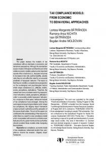
However, the FDR2 returned false since the trace < connect, search drug, send order, prepare order, deliver, prepare drug > appears in both models, but the trace < connect, search drug, send order, prepare order, deliver, prepare drug, purchaseorder, abort > is present in the peers–based distributed system and not in the LTS of the choreography. [a+4, b-4] make purchase order
[a,b-8] connect
0
1
[a+1,b-7] search drug
[a+3, b-5] prepare order
[a+2, b-6] send internal order
5
4
6
[a+5, b-3] timeout
[a+5, b-3] found [a+6, b-2] delivered
7 2
[a+2, b-5] prepare drug
3
[a+7,b-1] prepare drug
8
[a+3,b-4] done
9
[a+8, b] done
Fig. 9. Timed LTS model of the Ward-Pharmacy
The solution to this error in the LTS model is to make explicit an extra state in which the LTS is waiting for completing the purchase of the drug and add a timeout to this state If that time period expires then the LTS will reach an abort state signifying that the purchase is cancelled, since probably the distributor’s stock has been exhausted. The new LTS can be seen in Figure 9.
Choreography Modeling Compliance for Timed Business Models
6 Conclusion In order to enforce the realization of feasible choreographies within the realm of business proceses, we have presented a feasible formalization of BPMN 2.0 constructs. The complexity of model–checking the behavioral equivalence of an LTS, which specifies the possible behavior of a highly interactive system, against the actual behavior of a peer–based distributed application has been tackled out and a feasible, conceptually manageable, solution is proposed here. Of great importance to develop predictable and safe applications, it is to solve the choreography realization problem, i.e., a choreography is realizable if all the interactions specified in BPMN 2.0 diagrams are equivalent to those that can be executed by the interacting peers when the BP model is implemented in a service–description language, such as WS–CDL, and the BP rules are satisfied as well. We have solved that problem by transformation of the LTS and the peer– system model into a proces calculus named CSP+T. Process algebras, likes LOTOS–NT [14], CCS [10] or CSP+T [21] are good candidates for being chosen as the interactive abstract notation. These formal notations give expressive operators for translating BPMN 2.0 constructs Both notations, BPMN-CD and a process algebra, are high level languages and have similar operators: sequence, choice,interleaving. Furthermore, process algebras are supported by verification tools (like model–checkers SPIN, PVS, CADP, FDR, . . .) that can be used to check all the possible behaviors that take place in the model execution of any specified choreography. In this way, we can analyze and automatically verify the conformance of the defined choreography for services that communicate through messages in a general, distributed, and highly parallel system.
References 1. W. Aalst. Challenges in business process analysis. In: Enterprise Information Systems. Lecture Notes in Business Information Processing, v. 12: 27–42. Heidelberg: Springer, 2009. 2. A. Arkin, S. Askary, B. Bloch, F. Curbera, Y. Goland, N. Kartha, C. K. Liu, S. Thatte, P. Yendluri, and A. Yiu, editors. Web Services Business Process Execution Language Version 2.0. Committee Draft. WS-BPEL TC OASIS, 2005. 3. M. Bezem, J.W. Klop, R. de Vrijer. (”Terese”), Term rewriting systems. Cambridge University Press, 2003. 4. A. Cerone. From Process Algebra to Visual Language. In Proceedings of the Conference on Application and Theory of Petri Nets: Formal Methods in Software Engineering and Defence Systems, v. 12, Adelaide, 2002. 5. B. Dongen, W. Aalst. Multi–phase process mining: Building instance graphs. In: Conceptual Modeling–ER 2004. Lecture Notes in Computer Science, v. 3288:362– 376. Heidelberg:Springer, 2004. 6. Formal Systems Europe Ltd. Failures–Divergence Refinement – FDR2 User Manual. Formal Systems Europe Ltd., Oxford, 2005
Choreography Modeling Compliance for Timed Business Models 7. S. Ma, L. Zhang, J. He. Towards formalization and verification of unified business process model based on Pi calculus. Proceedings ACIS International. Conference on Software Engineering Research, Management and Applications 1, 2008. 8. L.E. Mendoza. Una Contribuci´ on a las T´ecnicas Avanzadas de Verificaci´ on de Procesos de Negocio (In Spanish). PhD Dissertation book, University of Granada (ISBN:978-980-12-4957-3), 2011. 9. L.E. Mendoza, M.I. Capel, M.A. P´erez. Conceptual framework for business processes compositional verification. Information and Software Technology,54,149:161, 2012. 10. Milner, R. (1989). Communication and Concurrency. International Series in Computer Science, 1989. ISBN 0-13-115007-3 11. Web Services Business Process Execution Language Version 2.0, 2007. http://docs.oasis-open.org/wsbpel/2.0/wsbpel-v2.0.pdf 12. OMG. Business Process Model and Notation (BPMN) -version 2.0. 13. C. Peltz.Web Services Orchetration and Choreography. IEEE Computer, 36(10), pp.46–52, 2003. 14. P. Poizat, G. Salaˆ un.Checking the realizability of BPMN 2.0 choreographies. Proceedings 27th Simposium of Applied Computing, 1927:1934, Riva del Garda(Italy), March 25-29, ACM,2012. 15. F. Puhlmann. Soundness Verification of Business Processes Specified in the Picalculus. Lecture Notes in Computer Science, no.4803: 6-23. 16. Z. Qiu et al. Towards the Theoretical Foundation of Choreography. Proceedings of the 16th international conference on World Wide Web (WWW’07), pp.973– 982, 2007. 17. A. Rozinat, W. Aalst. Conformance testing: Measuring the fit and appropriateness of event logs and process models. In: Business Process Management Workshops. Lecture Notes in Computer Science, 2006. 18. S.A. Schneider. Concurrent and Real–Time Systems – The CSP Approach.John Wiley & Sons, Ltd., 2000 19. S. Thatte. XLANG: Web Services for Business Process Design. Microsoft Corporation, 2001. http://www.gotdotnet.com/team/xml/wsspace/xlang-c 20. P.Y.H. Wong, J. Gibbons. A Process Semantics for BPMN. 10th International Conference on Formal Engineering Methods, ICFEM 2008 (Kitakyushu-City), Japan, October 27-31, 2008. In Lecture Notes in Computer Science 5256, 355:374, Heidelberg:Springer, 2008. 21. J. Zic. Time–Constrained Buffer Specifications in CSP+T and Timed CSP. ACM TOPLAS,16(6), 1661:1674,1994