MECHANISMS FOR BI-DIRECTIONAL COORDINATION BETWEEN VIRTUAL DESIGN AND THE PHYSICAL CONSTRUCTION
Abiola A. Akanmu, Graduate Research Assistant,
[email protected] Chimay J. Anumba, Professor and Head,
[email protected] John I. Messner, Associate Professor,
[email protected] Department of Architectural Engineering, The Pennsylvania State University, PA 16802, USA
ABSTRACT There is considerable growth in the use of virtual models in the construction industry. Many projects are now based on fairly sophisticated models but the use of these models is often limited to the design and tendering/bidding stage. Much more benefit can be derived from these models by extending their use to the construction, operation and maintenance phases of a facility’s lifecycle. A good way of achieving this will involve real-time bi-directional coordination between as-designed models and the physical construction. This will enable improvements in progress monitoring, construction process control, archiving as-built status and active control of building components and sub-assemblies. To maintain bi-directional coordination, computational resources are required to tightly integrate the virtual models and the physical construction. This is termed a Cyber-Physical systems approach. This paper focuses on describing the role of the Cyber-physical systems approach in enhancing bidirectional coordination. It highlights the mechanisms necessary to facilitate this and presents future deployment scenarios to illustrate the potential benefits to the construction industry. Keywords: Bi-directional coordination, Building Information Models, Cyber-Physical Systems, Physical Construction.
1. INTRODUCTION Over the past few years, there has been significant increase in the use of Building Information Models (BIM) in the AEC industry. BIM offers considerable potential for visualization, construction scheduling, cost estimation, clash detection, and as-built documentation thereby resulting in reduced project cost and duration, and increased productivity and quality. In-spite of these benefits of BIM, research has shown that it is still mainly used in the pre-bidding/preconstruction phase for pre-project planning services, clash detection and visualization services (Kunz and Giliman 2007). However, much more benefit can be derived from these models by extending their use to the construction, operation and maintenance, and decommissioning/demolition phases, thus enabling information flow throughout a facility’s lifecycle. It has been identified that information flow from design to construction is critical and this allows for design-build and other integrated project delivery methods to be favored (Ku and Mills 2010). Anumba et al. (2010) and Motamedi and Hammad (2009) also identified that integrating virtual models and the physical construction can improve the information and knowledge handling from design to construction and maintenance, hence enhancing control of the construction process. A good way of achieving this integration involves real-time bi-directional coordination between as-designed virtual models and the physical construction. This integrated approach will enable improvements in progress monitoring, construction process control, as-built documentation and sustainable building practices. To maintain bi-directional coordination, computational resources are required to tightly integrate the virtual models/building information models and the physical construction. This integration approach is termed a cyber-physical systems approach. In the context of this research, a
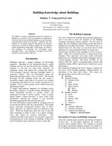
cyber-physical system is taken to mean the tight integration and coordination between virtual models and the physical construction (as shown in Figure 1). This paper focuses on describing the role of the cyber-physical systems approach in enhancing bidirectional coordination. It highlights the mechanisms and triggers for this bidirectional coordination. The paper also presents future deployment scenarios to illustrate the potential benefits of the proposed approach to the construction industry.
Bidirectional
Coordination
Virtual Model
Physical Construction
Figure 1: Bi-directional coordination between virtual models and the physical construction
2. ENABLING TECHNOLOGIES FOR CYBER-PHYSICAL INTEGRATION BETWEEN VIRTUAL MODEL AND THE CONSTRUCTION
SYSTEMS PHYSICAL
The key enabling technologies required for bi-directional coordination between virtual models and the physical construction are discussed below:
2.1 Virtual Prototyping/Building Information Models Virtual prototyping is the exploitation of simulation processes for the testing, evaluation and modification of prototypes in virtual design environments (Brandon and Kocaturk 2008). Virtual prototyping involves creating digital models of products to be analyzed in 3D and 4D using software such as Autocad, Revit, Navisworks, etc. These digital models, also known as virtual models, enable the visualization of buildings to be constructed, thus enabling identification and rectification of conflicts before construction (Huang et al. 2006). Virtual prototyping technology also involves information based models called Building Information Models which have the capacity to store embedded information that can be analyzed and utilized throughout the lifecycle of a facility. BIM has the ability to enable interdisciplinary collaboration throughout the life cycle of a building, the capability to easily manage change and the ability to easily transport information about the building from one life-cycle phase to the next. With the integration of this virtual prototypes/building information models with the physical construction, data delivered at project turnover (as-built model) is more complete and more structured. With the as-built model, facility managers can obtain visual information about the facility to be maintained. The as-built model also offers opportunities for improving the deconstruction process, as the procedure for demolition can be determined, and the material or components to be re-utilized identified and protected (Guo et al. 2010).
2.2 Wireless Sensors Sensors are being deployed to obtain information about facilities that are being constructed, processes and equipment that are being utilized in constructing these facilities, and monitoring the as-is
condition of an infrastructure throughout its service life (Akinci and Anumba 2008). Wireless sensor technology offers increased flexibility in terms of placement, reduced cost of installation and maintenance compared with wired sensors; this makes it suitable for adoption in the construction industry. Wireless sensors can be used to capture data from the physical construction and to update information in the virtual model. Examples of such wireless sensors include RFID tags, Placement sensors, ZigBee etc. RFID tags make it possible to assign unique identification numbers to components that they are attached and information can written to them to be accessed by personnel on the construction site using RFID readers. RFID tags are classified as passive and active tags (Era-build 2006). Passive tags are the most popular type of RFID tags because of their low cost. They do not have a battery, but they get their power from the RFID reader. On the other hand, active tags have an on-tag power supply like a battery, which emits a constant signal containing identification information but they are expensive. RFID tags have been utilized in the construction industry for tracking construction materials or components on site (Akinci et al. 2003; Goodman et al. 2006). Integrating RFID tagged components with their virtual representation in the model will enable as-built information stored in this tags on site to be accessed in the model (in the office). Also design changes made to virtual components in the model can be communicated to the tagged components for access by the construction personnel on site. Being able to identify tagged components in the model will enable facility managers’ opportunity to control the constructed facility. While RFID tags have shown great potential for identifying and tracking construction components (Motamedi and Hammad 2009; Chin et al. 2008), the use of this tags for construction progress monitoring still involves manually updating the tags of component status. However, placement sensors (such as magnetic sensors) track/detect when components are in contact. These sensors are presently being deployed in buildings for sensing when doors and windows have been opened. These sensors can be applied on the construction site for tracking real-time placement of building components; this has tremendous opportunity in enhancing real-time access to progress information, hence enabling quick decision making.
2.3 Mobile Devices Mobile devices are portable/small sized computing devices having a display screen for reading and writing information. Mobile devices have long been found useful in the construction industry for progress management (El-Omari and Molselhi 2008), managing punch lists (Menzel et al. 2002b), maintenance (Kim et al. 2008) and safety applications (Yabuki et al. 2002). Examples of such mobile devices include personal data assistant (PDA), smart-phones and tablet PCS. The tablet PCs offers several advantages compared with the PDAs and smart phones: Tablet PCs are capable of accommodating several kinds of information such as project models and specifications. Tablet PCs have large screen (unlike the PDA and smart phones) which can be used to navigate models and provides easily and quick entry of construction data. The major drawback of PDAs is the small screen size and limited ability to easily and quickly enter data. Most mobile devices have external features for data capture such as barcode scanners and RFID readers. Construction personnel can easily embed information through the screen to be written to RFID tags before installing/erecting building components. They can also scan the tags and barcodes using the embedded RFID and barcodes readers respectively, to read the tag information. Another important feature of mobile devices is the wireless connectivity. Data captured using mobile devices can be transferred wirelessly to a local or remote server.
2.4 Communication Network The communication network is one of the most important technology for enhancing bi-directional coordination between virtual model and the physical construction, as it enables the transfer and exchange of information between mobile and fixed devices such as PDAs, tablet PCs and desktop computers (Aziz et al. 2006; Skibniewski and Jang 2006). Examples of some communication networks being used in the construction industry include the internet, wireless local area network (WLAN) (WiFi) and the wireless personal area network (WPAN) (comprising of ultra wide band, Zigbee and Bluetooth). With these communication networks, data can be transferred or exchanged wirelessly between devices on the construction site, and between the construction site and the remote office, thus
enhancing collaboration amongst the project team. In the context of this research, data or information from the construction site can be transferred through the communication networks to the virtual model in the remote office and vice versa. The choice of communication network depends on a number of factors such as range, cost, data transfer rate, network topology and battery life (Xuesong et al. 2008).
3. PREVIOUS EFFORTS TO INTEGRATING VIRTUAL MODELS AND THE PHYSICAL CONSTRUCTION A number of researchers have investigated the integration of virtual models and the physical construction using different data acquisition technologies such as photographs, laser scanners, RFID tags etc. Below is a summary of the major efforts and their limitations.
3.1 Summary of major efforts Golparvar-Fard et al. (2009) investigated the integration of digital cameras and 4D CAD for the visualization of progress deviations in construction projects. This approach involves the superimposition of 4D CAD as the as-planned model into time-lapse photography and videotaping of the as-built progress data collection. This superimposed image enables discrepancies to be detected, quantified and cost values extracted. This process could also be time consuming as a large number of photographs will need to be taken to adequately capture the as-built information. In the case of bad weather such as snow, the use of photographs will be inadequate. Using laser scanners, Boche et al. (2008) developed an approach which involves integrating 3D CAD modeling and time-stamped 3D laser scanned data for automated project progress tracking. The approach enables automated recognition of 3D CAD model objects from site laser scans. Scans obtained from different days or from different site locations are compared by recognizing the 3D objects which differ in each scan to determine the construction progress. This object recognition approach can recognize the 3D model objects being built. It also enables tracking of the progress of the construction of pre-fabricated and installed elements. This approach will require taking a number of scans from different sides, thus making this approach time consuming. A number of researchers have utilized RFID tags for integrating virtual models and the physical construction: Chin et al. (2005) examined the use of 4D CAD and RFID tags for progress monitoring in supply chain management. RFID tags were placed on structural elements such as structural steel and curtain walls, to sense their status from the ordering stage through the delivery, receipt, and finally to the erection stage. The sensed status was captured in a 3D model to indicate progress status. The authors limited the research to status tracking but installation instructions and design changes (which often occur during construction) could be written to the 3D model and captured in the tags. Easy access to this information could greatly enhance the productivity on the project site. Motamedi and Hammad (2009) also investigated the use of RFID tags and BIM for lifecycle management of facility components. The authors proposed permanently attaching RFID tags to facility components where the memory of the tags is populated with BIM information taken from a BIM database. The BIM data stored on the tags provides a distributed database that allows access to different players who do not have real-time access to a central database. The authors demonstrated the feasibility of this approach by carrying out two case studies: The first case study demonstrated how the proposed approach will facilitate progress monitoring of construction projects. The status and timing information of a building component obtained from the BIM database can be merged with geometrical information from a 3D model to produce a 4D model which will help project managers and the facility management team to better visualize the status of the facility. In the second case study, RFID tags were used for storing information about fire safety equipment. Crucial information is converted to binary codes and stored on tags attached to extinguishers and valves. This information includes history and condition of the extinguishers and valves for inspectors and maintenance personnel without access to the central database. With the floor plans, the inspectors and maintenance personnel can visually locate the tags and access information from the tag using RFID readers. This approach is not suitable where a large number of components are to be tagged, as passive tags have limited memory and will need to be read at close range.
3.2 Limitations The aforementioned research projects have demonstrated the capability of integration of virtual models and the physical construction for better modeling of proposed facility, tracking of components on site and progress monitoring. However, there is still little or no mechanisms for ensuring bi-directional coordination between virtual models and the physical construction. For example, when a key component or sub-assembly is constructed or changed in the physical environment, there is no means of automatically updating the virtual model to reflect this. Conversely, if the design or erection sequence of a set of steel members is altered in the virtual model, there is no real time communication of this change to the construction personnel on site. There is also a lost opportunity for the use of sensors and other embedded instrumentation to control the construction process/constructed facility. A cyberphysical systems approach, which will enable this bi-directional coordination and enhance effective control of the construction process/constructed facility, is described in the next section.
4. ARCHITECTURE FOR CYBER-PHYSICAL SYSTEMS APPROACH A cyber-physical systems approach consists of two main features: the physical to cyber-bridge and the cyber to physical-bridge. The physical to cyber-bridge is the sensing process, which involves using sensors to acquire information about components or phenomenon. The cyber to physical-bridge represents the actuation which shows how the sensed information affects the system. In the context of this research, the actuation is taken to mean making control decisions from the sensed information and/or using the sensed information to physically control building components. The cyber-physical systems concept is illustrated in a proposed system architecture presented in Figure 2. The system architecture brings together the key enabling technologies discussed earlier (i.e. Virtual prototyping, Wireless sensors, Mobile devices and Communication network) as a framework for bidirectional coordination between virtual models and the physical construction. The architecture is based on multiple layers, which are explained as follows:
4.1 Sensing Layer The sensing layer consists of sensors which monitor different aspects of the construction process/constructed facility e.g. the temperature sensor (for monitoring temperature of a space), RFID tags and readers (for identifying and storing information about components), placement sensors (for tracking component placement), etc. Depending on the type of sensor used, this layer can also provide the construction personnel access to control decisions e.g. information captured in the RFID tag memory or information that can be accessed through the RFID tag id.
4.2 Device Layer This layer consist of the client devices (such as the PDA, tablet PC, mobile phones etc). This layer serves two purposes: providing access to sensed data from the sensing layer and enabling entry of information through the user interface.
4.3 Communication Layer This layer contains the Internet and wireless communication networks: wireless personal area networks (Zigbee and Bluetooth), wide area networks and local area networks (which use Wi-Fi to enable access to the internet). This communication networks connect mobile devices to allow for collaboration and information sharing between construction personnel on site. The communication networks also allow the data collected through the mobile devices to be transferred through the internet to the database in the contents and application layer.
4.4 Contents and Application Layer The contents and application layer contains the local database, database server and the control application. The type of control application depends on the context application to which the system is put. This layer stores, analyses and is constantly updated with information collected from both the communication and actuation layers. The stored information includes project management data (such as component type, as-built information, model update information, component lifecycle data and
application specific data). The control applications use the sensed data from the database to make control decisions which can be visualized using the virtual prototype in the actuation layer.
4.5 Actuation Layer The actuation layer contains the virtual prototype which is accessed through the user interface. The virtual prototype enables the user to visualize how the sensed information (from the contents and storage layer) affects the system. The human interface enables the user to visualize and monitor the sensed information from the contents and storage layer. The user can also embed control decisions into the virtual prototype through the user-interface to be accessed in the device layer. Actuation Layer User-Interface
Contents and Application Layer Control Application
Databases
Database server
Communication Layer
WLAN
WPAN
WAN
WiMAX
Device Layer
PDA Sensing Layer
Tablet PC
Smart-Phones
Wireless Sensors RFID System
Temperature Sensors
Humidity Sensors
Figure 2: The Cyber-Physical Systems Architecture
5. TRIGGERS FOR BI-DIRECTIONAL COORDINATION BETWEEN VIRTUAL MODELS AND THE PHYSICAL CONSTRUCTION There are several situations that trigger the need for bi-directional coordination between the virtual model and the physical construction. These include design changes, tracking and control of building components, different site conditions and temporal conditions required for constructability, and are briefly described below:
5.1 Design Changes During construction, design changes occur and these changes can be owner induced, intended to correct design mistakes, or necessitated by unforeseen site conditions. These changes constitute major causes of delays, disruption and disputes, and it is widely accepted that the effects of such changes are
difficult to quantify (Neelamkavil et al. 2008; Motawa et al. 2007). When these changes occur, they need to be shared accurately, consistently and in a timely manner between the project team members on the construction site so as to reduce risks such as time and cost overruns (Chin et al. 2008). These changes can be effected in the virtual model and communicated to the affected components on site. For example, changes to sizes of steel members can be made to the virtual model and the steel erectors can access this from the tagged pieces on site before installation/erection. This will go a long way to help the industry avoid rework, as critical information is received at the point of need, such as before the wrong members or components are installed.
5.2 Tracking and control of building components Building components such as light fixtures are identical and as such, not distinguishable. Being able to track each light fixture in a constructed facility will enhance the ability to control each fixture, thus improving energy management. Binding each physical component with its corresponding virtual component will enable facility managers/owners to differentiate each component in the model and use the model to remotely control each component. Also, facility managers can track damaged or faulty components remotely instead of the usual routine physical maintenance checks.
5.3 Different field conditions Different site conditions (from those originally anticipated) have been identified as one of the major causes of delay in construction projects (Assaf and Al-hejji 2006). These different site conditions need to be communicated to the design team on time and in an effective way so that decisions can be made. Also, differing site conditions might result in changes being made on site. These changes need to be documented in the as-built model for the operations and maintenance of the building facility. For example, the original design of a retrofit project calls for a door with a 1-hour fire rating (for non-load bearing assemblies) and the contractor (on site) discovers that the interior wall is actually load bearing. He will need to communicate this in such a way that the architect can easily identify the component and access the information. The architect will also need to communicate the decision about the component to the contractor on site.
5.4 Temporal conditions required for constructability During the preconstruction phase, certain temporal conditions required for construction are not anticipated and, as such, are not included in the design. These temporal conditions usually result in a re-evaluation of the design before construction can proceed. For example, during the steel erection process, a large mechanical equipment might need to be lowered into the building, this will require some steel members to be left out. The structural engineer will need to be informed of the particular pieces to be left out and their spatial information so that he can determine the capability of the remaining structure to support the loads temporarily. Being able to relay these information to the virtual model and in real-time to the structural engineer is important as this will enhance quick decision making.
6. APPLICATION SCENARIOS Two scenarios, illustrating the application of bi-directional coordination between virtual models and the physical construction, are presented here to show the practical application of the proposed cyber-physical systems approach.
6.1 Steel Placement This scenario describes how bi-directional coordination between the virtual model with the physical construction will enhance the installation of structural steel members. Each member is tagged using active RFID tags with embedded information on the erection sequence for the installation of the steel members. This is intended to avoid the problems that can occur when a member is in line for installation before the supporting members have been erected. The virtual model reflects the status of the steel erection (i.e. it can highlight which members have and have not been installed to date). The model also contains information about dependencies (i.e. which members need to be installed before
others). The following numbers illustrate the sequence of actions and correspond to the numbers in Figure 3. 1. After steel members have been fabricated, a change is made to the design (or a mistake is found). The structural engineer corrects this change, but it has an impact on the sizes of several other members. 2. Information regarding the changed/affected member sizes is communicated to the construction site and written to the RFID tags: The information from the model is initially captured in the database server, transferred through the internet and read by a fixed RFID reader (which has read and write capability). The reader/writer writes the information to the RFID tags of the affected members so that the contractor knows which pieces can be installed and which need to be replaced with larger members. Since the virtual model also contains dependencies, if the original installation sequence changes, the new sequence is also communicated to the RFID tags of the affected members.
Figure 3: Steel Placement Scenario 3. Before erecting each steel member, the steel erector scans the RFID tag with a PDA (having an in-built reader with read and write capability) and reads off embedded information. 4. As each steel member is erected on site, the steel erector updates the status of the RFID tags (from ‘on-site’ to ‘installed’ or ‘erected’) on the members by writing to the tags using the PDA. 5. The status change is detected by the fixed reader and communicated through the Internet to a project database. A control application (running on the remote office computer) loops through the database for new information and updates the virtual model with the new status, resulting in the affected member being highlighted (e.g. by a color change). This color change in the virtual model enables the model coordinator /project manager to monitor the progress of the structural steel erection from the remote office. 6. If a large mechanical equipment needs to be lowered into the building later during construction and this requires some steel members to be left out, the steel erector can identify the steel members and write this change to their tags. 7. The tag information is detected by the fixed reader through the radio frequency from the tags and communicated through the database to the virtual model, which is then updated with the new information, resulting in that member being highlighted. The role of the color change is to inform the structural engineer of the updated information relating to a steel member. 8. The structural engineer reads the information in the model, and evaluates whether the remainder of the structure is adequate to support the loads temporarily.
6.2 Light fixture tracking and control
The locations of individual items of bulk materials (such as light fixtures) within a building are not easily differentiable; as such, facility managers cannot control each item. This scenario (Figure 4) focuses on identifying and tracking the installed locations of light fixtures for the purpose of improving energy management in buildings. 1. On arrival at the site, the light fixtures are tagged with passive RFID tags (if the light fixtures are not already tagged) to identify and differentiate each component. 2. As each tagged fixture is installed, the electrical contractor scans the fixture tag using a tablet PC with an integrated RFID scanner. 3. The tablet PC has a virtual model of the facility. On scanning the tag on the fixture, the electrical contractor binds the tagged fixture with the corresponding virtual fixture in the model and changes the status to ‘installed’ in the model. Binding the physically tagged fixture with the virtual fixture (in the model), creates opportunities for the electrical contractor to create individual controls for the fixtures. This virtual model can be shared by the model coordinator, who monitors the progress of work in the site office and can identify which components have been installed and uninstalled. 4. During the building lifecycle, the facility managers and owners can remotely use the virtual model to identify and distinguish the locations of each fixture within a physical space for the purpose of enhancing access to individual lighting units and controlling the energy performance of buildings. 5. When the light fixtures are controlled remotely, control messages are sent over the Internet using the TCP/IP protocol to a device server. The device server sends the control messages in the form of an IP address to the bus-master. This bus-master filters and sends the control messages to the appropriate light fixture. 6. Facility managers can also remotely observe and query the status (ballast failure, lamp failure, power failure, device type) of each or group of fixtures remotely through the model. For example, the status and specification of defective fixtures can be communicated to the facility managers (in real-time) through the model so that they can replace them. This is particularly important as problems can be identified and diagnosed early, thus, reducing the need for routine maintenance checks and enabling the owner/facility manager control over the facility. This concept can be applicable to urban infrastructure street lights, electrical bill boards and similar installations, where the installation of the individual street lights can be monitored remotely for the purpose of distinguishing each fixture and controlling each fixture over the infrastructure lifecycle. Being able to digitally address each light fixture provides an opportunity to digitally address each fixture from the virtual model and to communicate any changes in the status of the physical fixture (e.g. defective) to the virtual model for operational and maintenance purposes. 1. light fixtures are tagged with RFID tags
3. Electrical contractor binds installed fixtures with virtual fixtures in the model.
Installed Light fixtures are scanned with the in-built reader
5. The Bus master sends and receives the messages to the appropriate fixture
Model is shared by the Facility Manager 4. Facility manager interfaces with virtual model to identify and control with fixture
2. The tagged light fixtures are installed on site
TCP/IP
Figure 4: Bulk material tracking and control
Device Server
Bus Master
7. SUMMARY AND CONCLUSIONS With the advances in information and communication technology, the cyber-physical systems approach offers potential opportunities for enhancing bi-directional coordination between virtual models and the physical construction. The cyber-physical system approach described in this paper involves the use of RFID tags to capture and store relevant information about tagged components, from the design model. The sensed information from the tags is used to make control decisions and to physically control the construction process/constructed facility. This approach has been demonstrated through the development of use-case scenarios. A system architecture is presented which describes the key enabling technologies including wireless sensors, mobile devices, communication network and virtual prototyping technology. The key conclusions that can be drawn from this work are: • RFID tags can identify components and store information; this makes the technology suitable for tracking design changes and relaying them to the construction site, and documenting asbuilt information; • Bi-directional coordination between virtual models and the physical construction has potential opportunities for improving project monitoring and control of construction process/constructed facility, tracking changes/model updates and communicating these to site in real-time, documentation of as-built status and sustainable practices; • Triggers for bi-directional coordination has been identified as design changes, tracking and control of bulk materials, different field conditions and temporal conditions required for constructability; • The developed scenarios indicate that cyber-physical systems approach plays an important role in enhancing bi-directional coordination between virtual models and the physical construction. Further work is needed to supplement one or more of the presented scenarios in an experimental laboratory prototype prior to full-scale deployment on a construction site. The latter is expected to identify practical implementation constraints.
REFERENCES Anumba, C., Akanmu, A. and Messner, J. (2010) “Towards a Cyber-Physical Systems Approach to Construction.” Construction Research Congress 2010: Innovation for Reshaping Construction, 1: 528-537. Akinci, B., Patton, M and Ergen, E. (2003) “Utilizing Radio Frequency Identification on Precast Concrete Components – Supplier’s Perspective.” Proc. 19th International Symposium on Automation and Robotics in Construction, 381 – 386. Akinci, B. and Anumba, C. J. (2008) “Editorial - Sensors in Construction and Infrastructure Management.” (ITcon), Special Issue Sensors in Construction and Infrastructure Management, 13: 69-70. Assaf, S. A. and Al-Hejji, S. (2006) “Causes of delay in large construction projects.” International Journal of Project Management. 24: 349–357. Aziz Z., Anumba C.J., and Law K., (2006) “Using Context-Awareness and Web-Services to Enhance Construction Collaboration.” Joint International Conference on Computing and Decision Making in Civil and Building Engineering, 3010-3019, June 14-16, 2006. Brandon, P. and Kocaturk, T. “Virtual Futures for Design, Construction and Procurement”, Blackwell Publishing Limited, ISBN: 978-1-4051-7024-6. Bosche, F., Haas, C.T., and Murray, P., (2008) “Performance of automated project progress tracking with 3D data fusion.” CSCE Annual Congress, Quebec City, QC, Canada, June 10-13. Chin, S., Yoon, S., Kim, Y., Ryu, J., Choi, C., and Cho, C. (2005) “Real time 4D CAD+RFID for project progress management.” Proceedings, Construction Research Congress 2005, ASCE, Reston, VA, 168–172.
Chin, S., Yoon, S., Choi, C., and Cho, C. (2008) “RFID + 4D CAD for Progress Management of Structural Steel Works in High-Rise Buildings.” Journal of Computing in Civil Engineering. 22:74-89. El-Omari S. and Moselhi O. (2008) “Integrating 3D laser scanning and photogrammetry for progress measurement of construction work.” Automation in Construction. 18 (1): 1-9. ERABUILD, "Review of the current state of Radio Frequency Identification (RFID) Technology, its use and potential future use in construction." National Agency for Enterprise and Construction, Tekes, Formas and DTI, 2006. Golparvar-Fard, M., Sarvarese S. and Pena-Mora, F. (2009) “Interactive Visual Construction Progress Monitoring with D4AR — 4D Augmented Reality — Models.” Building a Sustainable Future, Proceedings of the 2009 Construction Research Congress, 41-49. Goodrum, P. M, McLaren, M. A. and Durfee, A. (2006) “The application of active radio frequency identification technology for tool tracking on construction job sites.” Automation in Construction.15:292-302. Guo, H. L., Li, H. and Skitmore, M. (2010) “Life-Cycle Management of Construction Projects Based on Prototyping Technology.” Journal of Management in Engineering. 26:41. Huang, T., Kong, C. W., Guo, H. L., Baldwin, A., and Li, H. (2006) “A virtual prototyping system for simulating construction process." Automation in Construction.16:576-585. Ku, K., and Mills, T. (2010) “Research needs for Building Information Modeling for Construction Safety.” International Proceedings of Associated Schools of Construction 45nd Annual Conference, Boston, MA. Kunz, J., and Gilligan, B. (October 23, 2007). Values from VDC/BIM Use [WWW document]. URL http://cife.stanford.edu/VDCsurvey.pdf Menzel, K., Schapke, S., Eisenblaetter, K. (2002) “Mobile, wireless, handheld devices to support ework and e-commerce in AEC.” Computing in Civil and Building Engineering. Proceedings of the 8th International Conference, Taipei, Taiwan, April 3-5. Motamedi, A. and Hammad, A. (2009) “Lifecycle management of facilities components using radio frequency identification and building information model.” ITcon. 14: 238-262. Motawa, I.A., Anumba, C.J., Lee, S., Peña-Mora, F. (2007) “An integrated system for change management in construction.” Automation in Construction. 16(3): 368-377. Neelamkavil, J., Shen, W., Fung, D., Hao, Q. and Xie, H. (2008) “Need for intelligent system for construction process automation.” IRC Technical Report, March 2008. Skibniewski, M. J. and Jang, W.S. (2006) “Ubiquitous computing: object tracking and monitoring in construction processes utilizing ZigBee networks.” Proceedings of International Symposium on Automation and Robotics in Construction 2006, ISARC 2006: 287–292. Xuesong, S., Wu, C. and Ming, L. (2008) “Wireless Sensor Networks for Resources Tracking at Building Construction Sites.” Tsinghua Science and Technology. 13(67): 78-83. Yabuki, N., Shimada, Y. and Tomita, K. (2002) “An On-Site Inspection Support System Using Radio Frequency Identification Tags and Personal Digital Assistants.” Proceedings of the 2002 CIB w78 Conference, Aarhus School of Architecture, 12–14 June 2002, International Council for Research and Innovation in Building and Construction.