from the events in New Orleans during Hurricane Katrina. Within the figure ..... Critical Infrastructure Protection preparedness and recovery is a complex and ...
Proceedings of the 2006 Winter Simulation Conference L. F. Perrone, F. P. Wieland, J. Liu, B. G. Lawson, D. M. Nicol, and R. M. Fujimoto, eds.
CIMS: A FRAMEWORK FOR INFRASTRUCTURE INTERDEPENDENCY MODELING AND ANALYSIS
Donald D. Dudenhoeffer May R. Permann
Milos Manic Department of Computer Science University of Idaho at Idaho Falls Idaho Falls, ID 83402, U.S.A.
Idaho National Laboratory P.O. Box 1625 Idaho Falls, ID 83415-3605, U.S.A.
infrastructures that have become increasingly automated and interlinked. Most modern commercial infrastructures are composed of a collection of interconnected networks (both physical and computer based) that serve different purposes and have different owners. Indeed, even parts of the information residing on a single sub-network may have different purposes and different owners. Critical information and controls are passed between these component elements to coordinate necessary functions. The complexity and interdependency of these critical resource flows introduces nuances and potential vulnerabilities into the infrastructure. Natural disasters, deliberate attacks or accidental system failures within infrastructures may result in cascading effects that are neither readily apparent nor immediately understood. This paper examines the issues of interdependency modeling, simulation and analysis. The remainder of section one discusses infrastructures further. Section two examines infrastructure interdependencies and provides formalism for these dependencies. Section three then presents a software framework named the Critical Infrastructure Modeling System (CIMS©) which is used at the Idaho National Laboratory (INL) for critical infrastructure interdependency analysis.
ABSTRACT Today’s society relies greatly upon an array of complex national and international infrastructure networks, such as transportation, utilities, telecommunication, and even financial networks. While modeling and simulation tools have provided insight into the behavior of individual infrastructure networks, a far less understood area is that of the interrelationships among multiple infrastructure networks including the potential cascading effects that may result due to these interdependencies. This paper first describes infrastructure interdependencies, as well as presenting a formalization of interdependency types. Next the paper describes a modeling and simulation framework called CIMS© and the work that is being conducted at the Idaho National Laboratory (INL) to model and simulate infrastructure interdependencies and the complex behaviors that can result. 1
INTRODUCTION
In these days of National Security concerns following the 9/11 attacks and in the wake of the devastation of Hurricanes Katrina and Rita, the discussion of the protection and restoration of “Critical Infrastructures” has risen as a national concern and research area. The U.S. Patriot Act defines critical infrastructure as “systems and assets, whether physical or virtual, so vital to the United States that the incapacity or destruction of such systems and assets would have a debilitating impact on security, national economic security, national public health or safety, or any combination of those matters” (U.S. Congress 2001). The focus of this research, however, is not with individual infrastructures, but with the intertwining of resources and information demands that exist between them. Advances in information technology (IT) and the necessity to improve efficiency have resulted in
1-4244-0501-7/06/$20.00 ©2006 IEEE
1.1 THE INFRASTRUCTURE MODEL “Infrastructure is defined as the framework of interdependent networks and systems comprising identifiable industries, institutions, including people and procedures, and distribution capabilities that provide a reliable flow of products and services essential to the defense and economic security of the United States, the smooth functioning of governments at all levels, and society as a whole” (Clinton 1996). Within the course of this paper and also within the simulation environment CIMS©, infrastructures are represented graphically as a network composed of Nodes
478
Dudenhoeffer, Permann, and Manic and Edges. Within this context, nodes and edges have specific meaning and are defined as such: Definition 1 An infrastructure Node is an entity that acts as a source, produces, consumes, or transforms a resource. By the same token, however, a node may represent social or political factors of influence that do not manifest in physical form, but which can impact physical infrastructure. Definition 2 An Edge is a physical or virtual entity that acts as a conduit for flow for a physical quantity, information or influence. Therefore, an edge (or arc) between two nodes represents a direct level of dependence. Infrastructure networks, these collections of nodes and edges, represent a dynamic and complex structure. The ACIP, a European-based consortium devoted to the development of a roadmap for critical infrastructure protection research, provides the following examples illustrating these dynamics: • • • •
• •
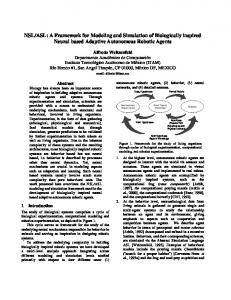
networks represents a very challenging and relative immature area of research (Dunn and Wigert 2004). 2 INFRASTRUCTURE INTERDEPENDENCY ANALYSIS What are infrastructure interdependencies and how are they modeled? To answer this question, Figure 1 illustrates a common representation of infrastructure interdependencies and the scenario of a flooding event and the subsequent response. Parallels to this scenario can easily be drawn from the events in New Orleans during Hurricane Katrina. Within the figure individual infrastructure networks are represented on a single plane. The parallel lines represent individual sectors or subsets within that particular infrastructure. The spheres or nodes represent key infrastructure components within that sector. For example, the energy infrastructure contains the sectors of electrical generation and distribution, natural gas production and distribution, etc. Ties and dependencies exist within each infrastructure between the different sectors. In the figure, the solid lines crossing sectors and connecting nodes represent internal dependencies. Additionally, however, dependencies exist between different infrastructures. The dashed lines represent the infrastructure interdependencies. The example in the figure is a simple attempt to relate the complexity of dependencies that may exist between components. In chaotic environments such as emergency response to catastrophic events, decision makers should
Growing Size: An increasing number of nodes and links between nodes with increasing structural complexity. Network Evolution: The link between nodes could change over time. Connection diversity: the links between nodes could have different weights, directions and signs. Dynamical Complexity: Nodes themselves could be non-linear dynamical systems in which the state of each node may vary in complicated ways. In a network, the state of each node can vary in time in complicated ways. Node Diversity: A network may be composed of many different types of nodes. There could be many different kinds of nodes. Interaction between factors: All of the above factors can interact to affect network dynamics. Here nodal dynamics affect connection weights. (Schmitz and Neubecker 2003)
These networks are inherently difficult to comprehend as a single entity. Coupled with primary and n-ary interdependencies, the resulting emergent behavior presents an even greater challenge in understanding. This collection of infrastructure networks and their associated interdependencies compose a highly nonlinear and complex system. A complex system being defined as “one whose component parts interact with sufficient intricacy that they cannot be predicted by standard linear equations; so many variables are at work in the system that its overall behavior can only be understood as an emergent consequence of the holistic sum of all the myriad behaviors embedded within” (Levy 1992). As such, the study of infrastructure interdependencies and the influence between
Figure 1: Infrastructure Interdependencies understand the dynamics underlying the infrastructures. Failure to understand these dynamics will result in ineffective response and poor coordination between decision makers and agencies responsible for rescue, recovery, and restoration. This could include
479
Dudenhoeffer, Permann, and Manic mismanagement of resource distribution including supplies, rescue personnel, and security teams. The result is the loss of public faith, and worse, the needless loss of life.
•
2.1.1 Interdependency Formalization
2.1 Types of Interdependencies
Building upon the preceding definitions, the following section defines a set of infrastructure interdependent relations while adding mathematical formalism. Definition 3 An infrastructure network, I, is a set of nodes related to each other by common function. The network may be connected or disjoint. It may be directional, bi-directional or have elements of both. Internal relationships/dependencies within the infrastructure I are represented by edge (a, b) with a, b ∈ I. Definition 4 Given Ii and Ij are infrastructure networks, i ≠ j, a ∈ Ii and b ∈ Ij, an interdependency is defined as a relationship between infrastructures and represented as the edge (a,b) which implies that node b is dependent upon node a. Depending on the nature or type of the relationship, this relationship may be reflexive in that (a,b) → (b,a). Therefore, let infrastructure I be denoted by the set of nodes and edges within the network, or I = { Ni, Ei1, Ei2} where Ni is the set of nodes consisting of the network I, Ei1 consists of the set of internal dependencies within network I, Ei1 = {(a,b) s.t. a, b ∈ I}, and Ei2 which consists of the set of interdependencies extending from infrastructure I, Ei2 = {(a,b) s.t. a ∈ I, b ∈ K} for some infrastructure K ≠ I. The types of interdependent relationships include physical, informational, geospatial, policy/procedural, and societal interdependencies as defined below. Definition 5 Physical Interdependency: (a,b)e . This defines a requirement, often engineering reliance of b on a. In other words, a loss of asset a results in a loss of asset b, ~ a → ~b. A simple example of this type of relationship is illustrated when a tree falls on a power line during a thunderstorm resulting in a loss of power to an office building and all the computers inside. Note, this effect is not driven by a single event, but is driven by the continuous state of a; i.e., b will not be restored until a is restored, b → a. Definition 6 Informational Interdependency: (a,b)i This defines an informational or control requirement between a and b. Information from asset a, while not necessary for the existence of node b, is essential for certain functionality in node b, ~ a → ~f(b) where f(b) is a function of operation for asset b. A supervisory control and data acquisition (SCADA) system which monitors and controls elements on the electrical power grid is an example of this type of relationship between the SCADA system and the power grid. While a loss of the SCADA system will not by itself shut down the grid, the ability to remotely monitor and
Infrastructure interdependencies refer to relationships or influences that an element in one infrastructure imparts upon another infrastructure. Interdependencies can be of different types. Rinaldi, Peerenboom, and Kelly (2003) describe dependencies in terms of four general categories: • • • •
Physical – a physical reliance on material flow from one infrastructure to another; Cyber – a reliance on information transfer between infrastructure; Geographic – a local environmental event affects components across multiple infrastructure due to physical proximity; and Logical – a dependency that exists between infrastructures that does not fall into one of the about categories.
Dudenhoeffer, Permann and Boring (2006) proposed a slightly different but similar categorization of: • • • •
Physical – direct linkage between infrastructures as from a supply/consumption/production relationship; Geospatial – co-location of infrastructure components within the same footprint; Policy – a binding of infrastructure components due to policy or high level decisions; and Informational – a binding or reliance on information flow between infrastructures.
The study of inter-dependency is not unique to infrastructure analysis. One parallel effort is that of Bühne et al. (2003) in his discussion of dependencies in feature modeling for use cases. Here he defines the following dependencies: • • •
Hinders-dependency – describes that the binding of one object has some negative influence on another object.
Requires-dependency – a binding of one object implies the need of another object, i.e., a required following; Exclusive-dependency – describes that the binding of one object excludes the selection of another object; Hints-dependency – describes dependencies where the binding of one object has some positive influence on another object;
480
Dudenhoeffer, Permann, and Manic operation breakers is lost. Likewise, this relationship may represent a piece of information or intelligence flowing from node a that supports a decision process in b. An example is the dispatch of emergency services. While the responders may be fully capable of responding, an informational requirement exists as to answering where, what, and when to initiate response. Definition 7 Geospatial Interdependency: (a,b)g While not necessarily represented as an edge in the network, this defines a relationship that exist entirely due to the proximity of nodes a to b. In other words (a,b)g → d(a,b) < ε for some predefined distance ε. Thus E(a) → E(b) where E(a) represents a physical event occurring at the location of node a. Examples include flooding or fire affecting all the assets located in one building or area. This relation is reflexive, (a,b)g → (b,a)g. Definition 8 Policy/Procedural Interdependency: (a,b)p This refers to an interdependency that exists due to policy or procedures relating an event or state change for node a to a subsequent effect on node b or Ej(a) → Ek(b). An interesting aspect of this type of relationship is that it may not exist prior to the event Ej(a), in other words, Ej(a) may drive the creation of the relation (a,b)p. Note that the impact of this event may still exist given the recovery of asset a from Ej(a). An example occurred with the bombing of the World Trade Towers. Upon the bombing of the towers with aircraft, “all U.S. air transportation was halted for more than 24 hours, and commercial flights did not resume for three to four days.” (DOE 2001) Definition 9 Societal Interdependency: (a,b)s . Similar in form to Policy/Procedural interdependence, this refers to interdependencies or influences than an event on an infrastructure component may impart on societal factors such as public opinion, public confidence, fear and cultural issues. Although no physical linkage or relationship may exist, consequence from event in one infrastructure sector may impact other infrastructures. Likewise, this influence may be time sensitive in nature, decaying as the time from the original event grows. So for (a,b)s, Ej(a) → Ek(b,t) which represents a decaying effect over time t. An example of this type of relationship is the impact of the 9/11 Attacks. After the restoration of air service following the attack, air traffic was significantly reduced as the public evaluated the safety of travel. The impact of this was significant resulting in layoffs in the airline industry and numerous bankruptcy filings by some of the smaller airlines (DOE 2001).
While the dependencies within an individual infrastructure network are often well understood, the region of interest in this paper is the influence or impact that one infrastructure can impart upon another. These cross infrastructure effects continue to grow as information technology pushes interconnectivity between all aspects of business. Therefore, the key effects to model and gain understanding of are the chains of influence that cross multiple sectors and induce potentially unforeseen n-ary effects. These chains, potentially composed of multiple interdependency types, compose the path {(a,b), (b,c), (c,d), ...(y,z)} representing the cascading consequence of an event or the derived dependency of node z on node a, denoted (aDz). Likewise the genesis of the chain may not be singular in that the end effect is the influence of multiple nodes, denoted by (abc..Dz). These paths may not be unique in terms of effect, they may change over time, and their behavior may be cumulative in nature, i.e., the end effect may the culmination of multiple predicated events. The intertwining of networks in this fashion represents a complex system where emergent behaviors are rarely fully understood. 2.2 Problem Space In the analysis of infrastructure interdependencies and the subsequent emergent system behaviors, three major problem areas exist, namely: 1. 2. 3.
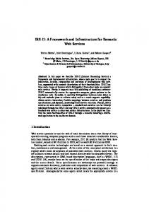
Given a set of initiating events {E(a), E(b), …} what is the cascading impact on a subset of nodes {x, y, z , …}. Given a set of nodes {x, y, z,…} and a desired end state, what is a set of events {E(a), E(b), …} that would cause this effect. Given a set of events {E(a), E(b), …} and a set of observed outcomes of on nodes {x, y, z,….}, is it possible to determine the derived interdependence (abDxyz).
These scenarios are illustrated in Figure 2. Clouded or incomplete knowledge of the infrastructure may complicate this issue. Thus the infrastructure mapping must rely on inferred influence patterns and bits and pieces of intelligence. This is most certainly true in terms of the aftermath of a storms such as Katrina or Rita, or when dealing with infrastructures outside of one’s control.
481
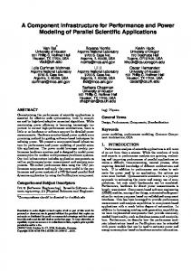
Dudenhoeffer, Permann, and Manic 3.2 System Architecture The CIMS© architecture uses an agent-based approach (ABM) (Rocha 1999) to model infrastructure elements, the relations between elements, and individual component behavior. The key characteristic of the agent and the simulations is that each agent exists as an individual entity which maintains a state, senses input, and possesses rules of behavior that act upon the inputs and either modify the state or produce an output. Each network within the simulation is modeled as a connected graph, G = (N, E), where N represents the nodes within the network and E represents the edges between the nodes. Edges also represent the relationship, i.e., interdependencies, between infrastructures. Nodes and edges may be deterministic in behavior or they may have stochastic properties. The nodes and edges of the infrastructure network are displayed in a 3D visualization as spheres and lines, respectively, or as predefined shapes. Colors can be associated with the state of the infrastructure elements or any other characteristic. Different infrastructures may be separated vertically in order to visually see the interconnections between them; likewise, infrastructure sectors may be further broken out. Visualization is further enhanced by the ability to incorporate potentially complex 3D objects. The model can be built upon an underlying bitmap, satellite photo, map, or chart. Nodes and edges are geo-referenced by latitude, longitude, and altitude or any other 3-dimensional coordinates. This structure permits the information to be quickly added to the model without the requirements of a geographic information system (GIS) database. Figure 3 illustrates multiple views of a CIMS© model of a facility and multiple infrastructure sectors. This particular model shows the consequence of the inadvertent tripping of a breaker to an electrical substation and the domino effect that occurs to the interlinked structures. CIMS© is a discrete event simulation and not representative of real time. The visualization is sequenced and updated as the simulation runs, to reveal the emergent or cascading system behaviors that develop as a result of the interdependencies between nodes. This makes the interrelationships between infrastructure networks and their consequences easy to quickly evaluate, facilitating the decision-making process. The goal of this simulation is not to produce an “exact” outcome, but to illustrate possible outcomes to enlighten the decision process. The second and third views in Figure 3 show the side views of the facility illustrating the relationship between infrastructures. The vertical lines indicate the different infrastructure sectors and the horizontal lines indicate a dependency between the infrastructures. The buildings can represent the physical entity or the capability associated with that building, such as a production process.
Figure 2: Interdependency Analysis Problem Space 3 CIMS MODELING AND SIMULATION FRAMEWORK 3.1 System Overview CIMS© was developed to examine the interrelationships between infrastructure networks and more specifically, the emergent systems behaviors that develop when one or more nodes within the system are perturbed. CIMS© and its ongoing development is sponsored by the National Security Division at the INL in its ongoing mission for providing Critical Infrastructure Protection and Preparedness. This work directly supports the following Presidential Directives: Presidential Decision Direction 63 (May 1998) and Presidential Executive Order 13231: Critical Infrastructure Protection in the Information Age (October 16, 2001). While many well defined models and simulations exist for infrastructure sectors such as electrical power grid models, traffic flow, rail systems, computer networks, etc., very few models exist that seek to tie these infrastructures together in a form representative of their actual implementation. Additionally, many of these models present a physics/engineering-based approach and are very good at individual sector analysis, but they do not necessarily support high level command and control. CIMS© takes a command-level approach seeking to provide decision makers with sufficient information in terms of mission capability without digging into the engineering level. For example, often it is enough for a decision maker to understand that electrical power is on or off via the amperage going into a facility. In this way, CIMS© models and simulates infrastructures and the interdependencies that exist between them at the level appropriate to the situation.
482
Dudenhoeffer, Permann, and Manic
Loss of one of the main breakers at an electrical distribution substation, resulting in a loss of power to half the facility.
CIMS© Side view illustrating the 3D structures and the separate infrastructures.
Physical Dependency
Side view showing the separate infrastructures and dependencies.
Figure 3: Infrastructure Components Surrounding a Facility Scenarios can be enacted through two different methods. First, to manipulate individual nodes or edges during “what if” analyses, the user can select specific nodes and edges and modify their state directly, removing or restoring capacity and watching the effect migrate through the system. Second, the user can develop baseline scripts tying together multiple events and observing the behavior. This can also be conducted in conjunction with individual node manipulation. Analysis is primarily visual in that consequence and cascading events are visually presented to the user. Less mature at this time are state reports and a running history report illustrating initiating events and cascading effects.
3.3 System Functionality Developed with a war gaming approach to modeling and simulation, CIMS© possesses the following functionality: • • •
483
Ability to model and visualize interdependencies; Ability to quickly construct infrastructure models using map images, satellite photos, and other electronic images; Ability to drill down and extract/change properties of individual infrastructure elements;
Dudenhoeffer, Permann, and Manic Ability to tie node behavior directly to live sensor input; Ability to link active information to simulated entities (i.e., web page links, text documents, video streams, and custom programs); Graphical (3D) representation of key infrastructure elements and the associated relationships; Ability to visualize bomb blast zones, flooding, and other areas of impact; Ability to model moving entities such as planes, traffic, people, etc.; Lightweight: program size (less than 10 Megabytes); and Mobile: works on multiple platforms, including Windows, UNIX, and Linux.
and restoring the critical sub-network is an important unsolved problem especially when confronted with the complexities of interdependence and subsequent emergent behavior. (Dudenhoeffer, Permann, and Sussman 2002). A genetic algorithm (GA) is being developed for integration with CIMS© to determine the optimal infrastructure assets to protect from attack or restore in a disaster situation. This will define the critical sub-network for the infrastructure of concern given information such as:
CIMS© has been applied to evaluate infrastructure at the INL and has been used as a validation tool with other infrastructure interdependency modeling projects for the DOE. Currently, CIMS© is being evaluated by the Louisiana Recovery Authority for applications in Hurricane Katrina and Rita recovery and restoration activities.
The GA will use this information to evaluate the resilience of infrastructure configurations using methods such as disabling arbitrary assets and letting the infrastructure stabilize through the CIMS© simulation. This can help determine the optimum (or ranking) of assets to restore or protect from attack or other disaster. The goal of this research is to accomplish one or more of the following:
• • • • • • •
• • • • • •
3.4 Interdependency Evaluation and Analysis
1. 2.
CIMS© provides a highly visual and interactive environment for observing the cascading effects and consequence of infrastructure perturbations. Through this visualization, a greater understanding of the emergent behaviors is achieved. The utilization of visualization by itself is complete, however, given the size and complexity of the networks additional search and analysis methods are required to identify event–effect relationships especially across multiple infrastructures. Therefore, the INL and University of Idaho are using artificial intelligence (AI) techniques to help refine the search space and identify subsets of possible interactions. This phase of research is just commencing and a brief description follows.
3. 4.
List of critical assets; Relative importance of each infrastructure asset; Cost to destroy the individual assets; Cost to repair the individual assets; Time to destroy the individual assets; and Time to repair the individual assets.
Find the critical sub-network(s). Find ways to mediate damages (which nodes can be protected before attack/accident/natural disaster, or which nodes should be restored first after the event). Identify weaknesses in the network. Accomplish above tasks on a dynamic network in the midst of asset loss.
4 CONCLUSIONS Critical Infrastructure Protection preparedness and recovery is a complex and challenging task. The complexity of infrastructure interdependencies compounds the enormous effort of coordinating relief and reconstruction efforts. This paper has presented a formalization to categorize infrastructure interdependencies. The purpose in this formalization attempt is to create a common language for discussion, algorithmic development, and analysis. Next the interdependency modeling framework CIMS© was introduced as a tool for infrastructure analysis supporting the ability to conduct “what if” scenario analysis. Finally, current research in the application of GAs to assist CIMS in the identification of the critical sub-network was described. In conclusion, the area of interdependency modeling is a very challenging research area. Network diversity and an ever-changing environment dictate the development of
3.4.1 Application of Genetic Algorithms Although CIMS© provides the ability for a user to generate multiple “What if?” scenarios, an automated process would be more efficient in generating multiple scenarios for determining the optimal infrastructure assets to protect from attack or restore in a disaster situation based on a predetermined set of critical infrastructure assets. This set of infrastructure assets which includes the critical assets and the assets they rely upon for protection and restoration is referred to as the critical sub-network. The “irreducible critical sub-network” is the minimum network that contains the mission essential assets, i.e., not all parts of an infrastructure are equally critical. Identifying, protecting,
484
Dudenhoeffer, Permann, and Manic multiple tools in modeling and simulation to assist in all aspects of analysis including preparation, response, recovery and restoration. United States will undoubtedly be faced with catastrophic events brought on by nature or through malicious act. It is key that the leaderships in charge of response, recovery and reconstruction operations has decision tools available to assist in dealing with the complexity of the infrastructure.
Buhne, S. G., and K. Pohl. 2003. Modelling Dependencies between Variations Points in Use Case Diagrams. In Proceeding of 9th Intl. Workshop on Requirements Engineering – Foundations for Software Quality (REFSQ’03), Klagenfurt/Velden, Austria. U.S. Department Of Energy Office of Critical Infrastructure Protection. 2001. Critical Infrastructure Interdependencies: Impact of the September 11 Terrorist Attacks on the World Trade Center A Case Study, p. 10. Rocha, L. M. 1999. Complex System Modeling: Using Metaphors from Nature in Simulation and Scientific Methods. BITS: Computer and Communications News. Los Alamos National Laboratory, November 1999. Available via [accessed March 26, 2002]. Dudenhoeffer, D. D., M. R. Permann, and E.M. Sussman. 2002. A Parallel Simulation Framework For Infrastructure Modeling And Analysis. In Proceedings of the 2002 Winter Simulation Conference, ed E. Yücesan, C. H. Chen, J. L. Snowdon, and J. M. Charnes, 1971-1977. Piscataway, New Jersey: Institute of Electrical and Electronics Engineers.
ACKNOWLEDGMENTS The CIMS© software was prepared by Battelle Energy Alliance, LLC under Contract No. DE-AC07-05ID14517 with the U. S. Department of Energy. The United States Government is granted for itself and others acting on its behalf a non-exclusive, paid-up, irrevocable worldwide license in this software to reproduce, prepare derivative works, and perform publicly and display publicly, by or on behalf of the Government. REFERENCES United States Congress. 2001. U.S.A. Patriot Act. Available via [accessed Mar 21, 2006]. Clinton, W. J. 1996. Executive Order 13010—Critical Infrastructure Protection. Federal Register, 1996. Vol. 61, No. 138: 37347-37350. Schmitz, W., and K. A. Neubecker. 2003. Architecture of an Integrated Model Hierarchy: Work Package 6, Deliverable D6.2, ACIP Technical Report IST-200137257: 32. Available via [accessed April 1, 2006]. Levy, S. 1992. Artificial Life – A report from the Frontier Where Computers Meet Biology. New York: Vintage Books. Dunn, M., and I.Wigert. 2004. International CIIP Handbook 2004: An Inventory and Analysis of Protection Policies in Fourteen Countries. Zurich: Swiss Federal Institute of Technology: 243. Rinaldi, S., J. Peerenboom, and T. Kelly. 2001. Identifying, Understanding, and Analyzing Critical Infrastructure Interdependencies. IEEE Control Systems Magazine, IEEE, December, 11-25. Dudenhoeffer, D. D., M. R. Permann, and R. L. Boring. 2006. Decision consequence in complex environments: Visualizing decision impact. In Proceeding of Sharing Solutions for Emergencies and Hazardous Environments. American Nuclear Society Joint Topical Meeting: 9th Emergency Preparedness and Response/11th Robotics and Remote Systems for Hazardous Environments. (In press).
AUTHOR BIOGRAPHIES DONALD D. DUDENHOEFFER is research scientist for INL in Idaho Falls, ID. He received his Masters of Science degree in Operations Research from the Naval Postgraduate School in 1994. His research interests include critical infrastructure modeling and simulation, military operations, command and control. He also holds the rank of CDR, USNR. His email address is . MAY R. PERMANN is a research scientist at the INL in Idaho Falls, ID. She received her B.S. in Computer Science from Idaho State University. Her research interests include Cyber Security with a focus on SCADA systems, high performance computing (HPC) and GAs. Her email address is . MILOS MANIC is the Graduate and Undergraduate Program Coordinator for the CS & ECE program, Center for Higher Education of University of Idaho at Idaho Falls, and an Assistant Professor at the Computer Science Dept., teaching graduate courses and workshops. He holds a Ph.D. in Computer Science from University of Idaho Boise and a Masters in Electronic Engineering and Computer Science from University of Nis. His research interests include artificial intelligence, decision support systems, and software reliability. His email address is .
485