Cinematographic Rules Applied to a Camera Network Petr Doubek1 , Indra Geys2 , Tom´ aˇs Svoboda3 and Luc Van Gool1,2 1
D-ITET/BIWI, ETH Z¨ urich, Switzerland {doubek, vangool}@vision.ee.ethz.ch, http://people.ee.ethz.ch/~doubek 2 ESAT/PSI-VISICS, Katholieke Universiteit Leuven, Belgium {Indra.Geys, Luc.Vangool}@esat.kuleuven.ac.be, http://www.esat.kuleuven.ac.be/psi/visics/ 3 CMP FEE, Czech Technical University, Prague, Czech Republic
[email protected], http://cmp.felk.cvut.cz/~svoboda
Abstract. We present a camera network system consisting of several modules of 2-3 low end cameras attached to one computer. It is not possible for a human to observe all the information coming from such a network simultaneously. Our system is designed to select the best viewpoint for each part of the video sequence, thus automatically creating one real-time video stream that contains the most important data. It acts as a combination of a director and a cameraman. Cinematography developed its own terminology, techniques and rules, how to make a good movie. We illustrate here some of these techniques and how they can be applied to a camera network, to solve the best viewpoint selection problem. Our system consists of only fixed cameras, but the output is not constrained to already existing views. A virtual zoom can be applied to select only a part of the view. We propose a view interpolation algorithm which makes it possible to create new intermediate views from the existing camera images. The combination of all these techniques gathers information from a complete camera network and produces one attractive real-time video stream. The resulting video can typically be used for telepresence applications or as a documentary or instruction video.
1
Introduction
Camera networks offer several viewpoints or a much larger field of view compared to a standard camera – this is an advantage for many computer vision applications. However, presenting the camera network output to people is not straightforward, because they cannot observe so many information streams simultaneously. This is a well-known problem in surveillance control rooms, where multiple streams converge. Nowadays, we still need a human editor to organize the data into a well structured and visually pleasant output. Ideally, the system itself should perform the task of selecting the important data and finding a suitable way to present them to the user. In this paper, we focus on the case of one person who moves through a room while performing certain actions and where the room is observed by a camera network. The user is interested in seeing the person and his/her actions. Our goal is to create a fully automatic system. It should act as a combination of a cameraman and a director, selecting the best viewpoint for each part of the video sequence, thus creating a low-cost documentary or training video or a real-time video stream for a telepresence application. High numbers of viewpoints and large fields of view offer possibilities to produce a single video stream, which provides an even better experience to the audience than actually being in the scene. However, it can also lead to confusing the audience and distracting it from the important content. Cinematography, the art of movie making, took this challenge more than hundred years ago and developed its own terminology, techniques and rules from which we can learn. Not all of them are applicable in our case, because a movie director has a complete control over the scene and even a cameraman shooting a documentary, although not necessarily influencing the scene, has at least a much better understanding of events and actions than an automated system can have nowadays. In this paper, we explore the use of some basic cinematographic rules for selecting the best view available in a camera network. Our system is not constrained to camera views only. A virtual zoom makes it possible to select only a part of the view. Moreover, a virtual camera can be generated between two existing cameras by view interpolation. Most of the time, one of the existing views is suitable, but at certain moments the virtual camera can be useful to maintain the continuity of the whole sequence. Of course, we are not the first to look into structuring (multi-view) video data. Bobick et al. [3] worked with a single camera observing a chef during a cooking show. Their goal was to replace the human cameraman with a computer so that the human director can give the same kind of orders – requested shot types – to the computer. The detection of the chef, his head and hands was context based with the context provided by the script. No viewpoint selection was done other than virtual zooming on a fixed camera. In the Aviary project [15], humans and specifically their faces are tracked in a meeting room and face closeups are provided by pan-tilt-zoom cameras. Producing a single output video stream is not a goal of that project. Khan et al. [11] perform tracking and view switching with an uncalibrated multi-camera setup which is initialized by one
person walking through the room to find the boundaries of the fields of view of the cameras. A detailed view on actions is not provided, the only criterion is to keep the person visible. A simple switching between neighboring cameras is also presented in the tracker by Cai et al. [4]. Researchers in the field of virtual reality and computer animation already employed cinematographic techniques [16, 2] for real-time positioning of the virtual camera. In these applications, a complete scene model is available which allows to easily render a view from any viewpoint. The subject is usually virtual, controlled by a keyboard, a mouse or another device. Thus the system has exact information about the position and actions of the subject as well as context information from the scene model. Without this data at hand, we have to rely on computer vision methods. A recent example of view interpolation is the work of Criminisi et al. [5], where an interpolation of a stereo pair of only an upper body is made. Their system is based on a dynamic programming algorithm for the generation of the depth map. An attempt to make an interpolation of a person out of five viewpoints has also been done by Yang et al. [18]. An intermediate image from a viewpoint in the middle of 5 cameras, setup very near each other, is generated by making use of a plane sweeping algorithm. Our algorithm is able to make a good interpolation by using only two input images. We can also deal with reasonable wide-baseline situations. This is mainly obtained by adding extra constraints to the fragment program, executed during the plane sweep. A 3D mesh is created for both the foreground and the background. As the final interpolation result, the input textures are projected and blended on this mesh. The paper is organized as follows. It starts with a short introduction of our multi-camera system and the methods used to detect the person in Sec. 2. Cinematographic rules and their usage are described in Sec. 3. Section 4 deals with the virtual view generation. An experiment in Sec. 5 discusses experimental results.
2
Multi-Camera System
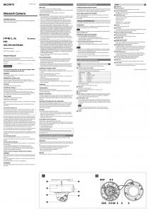
Our camera network [6] utilizes low-cost consumer hardware. FireWire or network IP web cameras are attached to Linux PCs, usually 2-3 cameras per PC, see Fig. 1(a). Laptops can be used instead of desktops and we already tested a mobile version with two laptops and six cameras in an industrial environment. The software [6] consists of several processes. They exchange data through shared memory if on the same computer, otherwise through a TCP/IP protocol. Local image processing servers run on each computer with attached cameras, and they perform the algorithms that only need an image from one camera. Best view selection and 3D calculations for tracking and view interpolation run on one control computer. This computer can also have cameras attached to it at the same time. Our view selection is based on the position and actions of the human. The overall body, the head and the hands are all tracked. People are segmented
(a)
(b)
Fig. 1. (a) FireWire web cameras and their arrangement into a network. (b) 3D path of a worker in an industrial facility (Framatome, Erlangen, Germany) inserted as white spheres into a VRML model.
out from the image using a background model that is previously learnt from an empty scene [7] i.e. the scene without people present. Connected foreground components are extracted, together with their silhouettes. The head and hands are detected as skin colored [10] blobs within this body region. Although it is possible to detect multiple people, we assume in this paper that there is only one person in the scene. The 3D position of the top of the head is reconstructed using N-view linear reconstruction [8] on every time frame. See Fig. 1(b) for the resulting 3D path. The reconstruction requires the visibility of the person in at least two views and a prior calibration of the multi-camera system, performed by moving a laser pointer through a scene [14].
3
Applying Cinematographic Rules
The algorithm performs the following steps for each frame: 1. Detect humans, faces, hands/arms in views and calculate their 3D positions if possible. This step was already covered in Sec. 2. 2. Decide which criterion should be used for the best-view selection. 3. Select the best-view according to the chosen criterion and perform virtual zoom or view interpolation if required. We used a book by J. Mascelli [12] to find out how cinematography approaches steps 2 and 3. Movie making is an art and there is certainly a place for creativity, breaking the rules and creating new techniques. However, following the rules results in a technically good movie which is for our application much
more important than being original. First, an overview of the techniques is given together with ideas how our camera network can benefit from them. The actual implementation is explained at the end of this section. 3.1
Choosing a Criterion – Calling a Shot
The objective is to produce single, clear video sequence of one person, the subject, performing a task in one room, the scene. The sequence is composed from several shots – a new shot starts each time the viewpoint or size of the depicted area changes significantly. With the area we mean the visible part of the scene. Four shot types can be applied in our case: – – – –
long shot shows a big part of the room and gives an overview, e.g. Fig. 4(a) medium shot includes upper half of the body, e.g. Fig. 4(i) close-up provides detailed view on face or hands, e.g. Fig. 4(j) insert displays letters, posters, projected slides or computer screens
The cinematographic theory also distinguishes shots by eyes through which the audience is looking. Objective shots represent the view of an uninvolved observer – we use this type of shot almost exclusively because each camera in our network is an uninvolved observer. Subjective and point of view shots are taken from the subject’s viewpoint or almost from that viewpoint in the second case, see Fig. 3. It is important to precede them with a head close-up of a subject looking off-screen, otherwise the audience might get confused. With a camera network, these shots can be realized either by a head-mounted camera or by virtual view rendering as shown for example in [9]. It is a director’s work to call a shot – for example to tell a cameraman “closeup of the hands”. This is a criterion to select the camera angle (this term means both viewpoint and area covered) and it is a cameraman’s task to find the best angle according to the criterion. A logical use of shot types for our purpose is proposed in Table 1.
(a) While the subject is moving show a long shot to provide spatial orientation to the audience, e.g. Fig. 4(a,c,d,k). (b) When the subject stops the movement (for example to operate a machine) show a medium shot (with the hands and face visible) or a hands close-up to allow the audience to see the action in detail, e.g. Fig. 4(b,i,j). (c) If the subject stops movement and does nothing except looking, generate a subjective shot by view interpolation, e.g. Fig. 3. (d) When the subject looks at a projected slide or a computer screen, use an insert to show the screenshot (taken directly, not by camera). This would require information about 3D positions of screens etc. which has not been included yet. Hence, such shots are not being used yet. Table 1. Shot types used in our algorithm.
The sequence of shots can be arranged as progressive/regressive, contrasting or repetitive. The progressive sequence first introduces the scene in a long shot and then progresses to the details in a medium shot and close-up – so using a long shot for an overview and closing-up on an action is a progressive sequence, see Fig. 4(h-j). Using only this technique in an entertainment movie is predictable and boring, but in our case it is suitable. A contrasting sequence uses opposing camera angles. A repetitive sequence repeats shots of different subjects from a similar angle – for example head close-ups of speakers in a talk show. Our automated system has limited ability in comparison with the human director. It does not know or ’understand’ the context, cannot control the person and consists of fixed cameras only. It assumes nothing about the path that the person will follow or about his/her actions. Cameras can be (and should be) positioned so that some of them have a good view on the whole scene and others are close to the places where the important actions are likely to happen. However, from the point of view of the algorithm all cameras in the network are equal, running the same algorithm with the same parameter settings.
3.2
Best Angle Selection
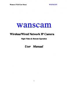
Cinematography prefers a viewpoint that has three-quarter angling with respect to the subject. That means the subject is seen in a front-side view at approximately 45 degrees which provides the best 3D feeling. However, following this recommendation strictly in a network of fixed cameras would require a great amount of view interpolation. Therefore, we select an existing camera with the most front-side view, e.g. 4(c,k). An objective shot of a room should be taken from the average human eye level at a level angle, i.e. not tilted up or down. This rule is taken into account when positioning the cameras, although the available camera positions are usually limited. For neatness, it is important to maintain an action axis rule when switching between cameras, as illustrated in Fig. 2(a). The camera is required to remain on one side of the action axis, which could be the line of movement or the line between the person and the object, he manipulates The purpose of this rule is to preserve the direction of movement of the subject or the facing direction, because a sudden change from left to right movement breaks the feeling of continuity and disturbs the audience. The direction can be changed in an pleasant way by inserting a head-on or tail-away shot – a view from a camera on the action axis looking along the axis. However, there are two problems with applying the action axis rule in a camera network like ours. First, if the algorithm should be used also for telepresence applications it has to work in real-time and start selecting a camera even before any prediction of the action axis is known. Second, in most cases there is no real camera in the required position for a head-on or tail-away shot, so an interpolated view has to be used for changing the side of the action axis, see Fig. 4(e-g).
5
4 1 3 2
(a) (b) Fig. 2. (a) Action axis rule. The person (circle) moving along the line is shown only by cameras 1-3. For switching to camera 5, a head-on shot from camera 4 has to inserted. (b) The bounding box around detected skin blobs, the minimal and maximal margin.
3.3
Implementation
We implemented three main criteria for viewpoint selection. These criteria are evaluated every frame for every camera. A specific visibility measure is defined for each criterion. We explain first the measures that are used for deciding about the type of shot. The simplest criterion measures the view suitability on the basis of the size of the biggest 2D object in the frame. The measure is divided by a constant greater than one when the object touches the left, right or top border of the image frame. In this case, it is likely that important parts of the human are cut off, which decreases the suitability of the view. This criterion is specifically used to select a viewpoint for an overview long shot (Table 1a) when no 3D objects are tracked. This occurs typically when the person just entered the scene and is visible only by one camera. The second criterion is also used for the selecting of a long shot (Table 1a), but it requires a Kalman filtered velocity vector of the tracked 3D object as its direction of movement. The angle between this vector and a line of sight for each camera is calculated and the measure indicates how close the view on the person is to the optimal three-quarter angle, see Sec. 3.2. But it is set to zero when the person is not well inside the image – for instance when he is too close to the camera and the shot is no more a long one. Medium/close-up shots (Table 1b) use a third criterion based on skin blobs. In one frame, there can be maximum three blobs, one for the head and two for the hands. The visibility measure used here, is defined as number of the skin blobs multiplied by the sum of their pixel sizes. It favors viewpoints with a close view on the face and both hands. These criteria have to be combined with mechanisms that prevent fast successions of viewpoint changes: – A visibility measure given to a specific camera is only updated in a linear way. Practically, this means that a camera must deliver a good view on the person for several frames, before it gets a high rate. – Switching to a novel view is not immediately done when a new camera obtains the highest visibility measure mnew . A ’resistance’ factor r > 1 is defined and switching is only performed if mnew > rmold , where mold is the visibility measure of the camera selected in a previous frame.
A third constraint to the switching implements the action axis rule (see Sec. 3.2). It applies only to the front-side view criterion because the 3D velocity vector is needed. Change of viewpoint is prevented if the cameras are on different sides of the 3D velocity vector unless an insertion of a head-on or tail-away shot is possible. This algorithm is only an approximation of the action axis rule. Better results could be achieved by analyzing the whole path of the person after recording a video and finding the action axis more precisely. The analysis cannot be applied for on-line scenarios however, it might be useful in a video postproduction. The criterion to be applied is decided on using the following rules in descending priority: 1. moving 3D object → call a long shot using the front-side viewing criterion 2. standing 3D object and the skin blob visibility measure is sufficiently high in one camera → call a medium/close-up shot 3. inactive 3D object → generate a subjective view preceded by a head close-up 4. call a long shot using the biggest 2D object criterion The rules are based on a velocity of the 3D object which is already filtered and on a skin blob visibility measure which is linearly updated. These refinements contribute to the stability of criterion selection. The virtual zoom rectangle (if a medium shot or close-up is required and no camera is close enough) has to be chosen carefully to give the audience an impression of a smoothly panning, tilting and zooming camera. We cannot simply take the bounding box with correct aspect ratio around tracked object(s) as the zoom area. Noise in the object detection would lead to a ’shaking camera’ and parts of objects would be cut off. Therefore, we define a minimal and maximal margin around the bounding box as a constant percentage of the box size. When the previous close-up area is between these margins (see Fig. 2(b)) our virtual camera is kept still. Otherwise, the close-up area is linearly updated to fit between the margins. The maximal virtual zoom factor is limited to keep acceptable resolution. Currently, the view interpolation is not directly integrated in our on-line system. Instead, a text request is generated and these instructions are used later for creating the interpolated views.
4
View Interpolation
With the help of the cinematographic rules one can derive good viewpoints. These can correspond to the place where a ’real’ camera is standing or somewhere in between. Depending on the special distribution of the cameras and the required location, it is possible to use the nearest camera view, or it is necessary to generate the required view through interpolation. The view interpolation is mainly implemented on the graphical board. This results in a modest usage of the CPU, so that it does not slow down the viewselection. Since a segmentation is already done on the images, it is possible to process foreground and background separately.
For the foreground, a plane-sweeping algorithm [1] is used to extract the 3D information, stored in a depth map. After postprocessing this depth map, it is sampled on a regular grid. A 3D mesh is formed through the 3D points corresponding the sample points. The foreground textures are projected and blended on this 3D mesh. For the background, we can apply exactly the same algorithm as for the foreground. However if the background is rather planar, as it is often the case in indoor scenes, it can be sufficient to model the background as a plane. The background textures can then be warped on this plane by a homography, thus creating a mosaic. Since the background is static and the cameras are fixed in our network, it is only necessary to calculate the 3D information for the background once. For generating interpolated frames, it can then just be re-rendered, and re-textured to compensate for illumination changes. The intermediate view is obtained by rendering the triangle mesh of the foreground together with the triangle mesh or the plane representing the background. Due to the use of the texture environments, it is possible to render the textures simultaneously on these meshes, while adjusting the blending factor dependent on the viewing position. The visualization is obtained by specifying the viewing directions in OpenGl in exactly the same way as when an intermediate camera would be pointed to the scene. In contrary to earlier work like [17], which mainly mainly proved feasibility of hardware accelerated plane sweeping, we make this process fully automatic and more robust. A sparse correspondence search, followed by a triangulation is performed to estimate the depth range of the background. A SUSAN corner detector [13] is used to select the features. The corners are matched in the two images, based on the knowledge of the epipolar geometry. Erroneous correspondences are avoided by adding a similarity criterion and restrictions to the flow. In case the background is presented as a mosaic, a plane can be fitted through these points. Otherwise the points give a good indication of the position of the background and the range that has to be covered by the plane sweep for the background, without any manual intervention. The range in space that has to be covered for the foreground-sweeping process can also be limited until this depth. For the first interpolated frame, we start the foreground sweeping at the position where the frusta of both cameras cut each other. For the next frames, the search range can be limited to a smaller range around the foreground object. This more accurate range can be determined by evaluating the distribution of the depth values, that result from the plane sweep. It can be updated every frame while the person is moving. The plane sweeping is done by rendering several planes parallel to the image plane of a ’virtual’ camera, located in between the real cameras. The images of both real cameras are projected onto the planes and the Sum of Absolute Difference (SAD) is calculated for every pixel, using the fragment program. We implemented the necessary information to identify a pixel as a part of the foreground as a mask, which is stored in the alpha channel of the textures. This way, false matches between foreground and background can be avoided. The system
becomes more robust, certainly for more wide-baseline situations. The fragment program executed by the GPU also differs from any earlier implementations. Mainly by using both the depth and the texture buffers, a considerable amount of overhead can be eliminated, resulting in a further speed up of the algorithm. The quality of the correspondences is improved by correcting for radial distortions. This is performed on the graphical board by projecting the textures on an inversely deformed NURBS interpolant.
5
Results
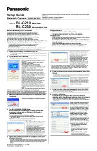
In our experiment, we used 6 FireWire web cameras attached to three Linux 3GHz PCs to cover a room of size 4.5 by 8 meters. The camera network runs at framerate 5-10 fps at 640x480 pixel resolution. Some image processing operations are performed on downsampled images. Figure 4 demonstrates how cinematographic rules are employed as described in Sec. 3. The man enters the room. His 3D position cannot be reconstructed yet as he is visible to only one camera. Therefore a long shot with the biggest 2D object is selected (a). A medium shot of his head and hands is shown when he stops to take a bag out of a cabinet (b). Then he moves again. A long shot from a camera with a front-side view is selected (c). Several frames later, another camera becomes more suitable due to the angle (d). However, due to the action axis crossing (notice opposite direction of movement) an insertion of a tail-away shot is required. See fig. (f) for an example of an interpolation from the views (e) and (g). As the man approaches the desk and takes out a laptop, the shots change progressively from an overview shot (h) to medium shot (i) and close-up (j). When he walks away a front-side long shot is shown (k). A subjective shot was not called in this sequence, because the subject did not stop long enough. We illustrate this type of shot in Fig. 3.
Fig. 3. A subjective shot can be inserted by estimating the viewpoint of the person and creating the corresponding interpolated view. Here, we try to create the impression that the man, first shown in a head close-up, focuses his attention on the center of his field of view by virtual zooming.
The experiment confirmed that the algorithm can provide a reasonable long or medium shot when the proper shot type is called. Mechanisms for preventing
frequent viewpoint changes proved their importance, because the audience tolerates slightly non-optimal viewpoint much more easily than over-use of viewpoint switching. The close-up ability is limited by the number and the resolution of the cameras. The subject has to be approximately within one meter of a camera to make a good hands or face close-up. Active pan-tilt-zoom cameras could enhance the close-up range. However, they would greatly increase the price of the system and complicate the calibration. Probably the biggest issue of the system lies in the prediction of subject’s velocity vector. In an office environment, a person typically does only a few steps before stopping or changing direction, which makes it difficult to predict the velocity vector. The calculation of a difference from the optimal three-quarter angle or an action axis calculation are influenced by this. Also, small changes in position are likely even during some activities, e.g. taking an object from a cabinet. Therefore, the system sometimes considers a change in position during an activity as a movement and calls a long shot. Analysis of subject’s path during postprocessing might be one of the solutions to this problem.
6
Conclusion
We proposed a methodology, inspired by well established cinematographic rules, for creating a single pleasant video stream from a camera network. The method was demonstrated on a sequence featuring one person walking in a room. Our system produces a video which informs the audience with the optimal view at any time where the person is and what he/she is doing. The best angle selection algorithm uses the results of tracking the person and his/her face and hands. Two types of shots are mainly used to generate the output stream – a long shot for a scene overview at the start or when the person is moving and a medium shot or a close-up upon an interesting action. The set of available camera angles is extended not only by virtual zooming, but above all by the creation of ’virtual’ cameras by view interpolation during postprocessing. The portable version of our camera network allows a quick setup at a new location. It can be used in a real-time mode for telepresence applications, or for creating training videos by postprocessing. For the moment, we are working on the integration of the on-line view interpolation with the rest of the algorithm. In the future, we want to tackle more complicated scenarios which might involve multiple humans or an interaction between them and multiple scenes – for example several rooms in one building. Using a probabilistic framework for selecting a shot type and a viewpoint could be helpful in this type of scenarios.
Acknowledgments The authors gratefully acknowledge support by the Swiss SNF NCCR project ‘IM2’ and ETH Z¨ urich project blue-c-II. Tom´ aˇs Svoboda was supported by The Grant Agency of the Czech Republic under project GACR 102/03/0440.
References 1. S. Baker, R. Szeliski, and P. Anandan. A layered approach to stereo reconstruction. In Proc. of CVPR’98, pages 434–441, 1998. 2. William H. Bares, Luke S. Zettlemoyer, Dennis W. Rodriguez, and James C. Lester. Task-sensitive cinematography interfaces for interactive 3d learning environments. In Intelligent User Interfaces, pages 81–88, 1998. 3. Aaron F. Bobick and Claudio S. Pinhanez. Using approximate models as source of contextual information for vision processing. In IEEE Workshop on Context Based Vision (ICCV95), 1995. 4. Q. Cai and J.K. Aggarwal. Tracking human motion in structured environments using a distributed-camera system. IEEE Transactions on Pattern Analysis and Machine Intelligence, 21(12):1241–1247, November 1999. 5. A. Criminisi, J. Shotton, A. Blake, and P.H.S. Torr. Gaze manipulation for oneto-one teleconferencing. In ICCV 03, October 13-16, 2003. 6. Petr Doubek, Tom´ aˇs Svoboda, and Luc Van Gool. Monkeys — a software architecture for ViRoom — low-cost multicamera system. In James L. Crowley, Justus H. Piater, Markus Vincze, and Lucas Paletta, editors, 3rd International Conference on Computer Vision Systems, number 2626 in LNCS, pages 386–395. Springer, April 2003. 7. Nico Galoppo von Bories, Tom´ aˇs Svoboda, and Stefaan De Roeck. Real-time segmentation of color images — implementation and practical issues in the blue-c project. Technical Report 261, Computer Vision Laboratory, Swiss Federal Institute of Technology, March 2003. 8. R. Hartley and A. Zisserman. Multiple View Geometry in Computer Vision. Cambridge University Press, Cambridge, UK, 2000. 9. M. Irani, T. Hassner, and P. Anandan. What does the scene look like from a scene point? In Proceedings of ECCV 2002, LNCS, pages 883–897. Springer, May 2002. 10. Michael J. Jones and James M. Rehg. Statistical color models with application to skin detection. International Journal of Computer Vision, 46(1):81–96, 2002. 11. Sohaib Khan, Omar Javed, Zeeshan Rasheed, and mubarak Shah. Human tracking in multiple cameras. In International Conference on Computer Vision, July 2001. 12. Joseph V. Mascelli. The five C’s of cinematography: camera angles - continuity - cutting - close-ups - composition / motion picture filming techniques simplified. Cine/Grafic Publications, Hollywood, California, 1965. 13. S. Smith and J. Brady. Susan - a new approach to low-level image processing. International Journal of Computer Vision, 23(1):45–78, 1997. 14. Tom´ aˇs Svoboda. Quick guide to multi-camera self-calibration. Technical Report 263, Computer Vision Lab, Swiss Federal Institute od Technology, Zurich, July 2003. http://www.vision.ee.ethz.ch/˜svoboda/SelfCal. 15. Mohan M. Trivedi, Ivana Mikic, and Sailendra K. Bhonsle. Active camera networks and semantic event databases for intelligent environments. In IEEE Workshop on Human Modeling, Analysis and Synthesis (in conjunction with CVPR), June 2000. 16. Li wei He, Michael F. Cohen, and David H. Salesin. The virtual cinematographer: A paradigm for automatic real-time camera control and directing. Computer Graphics, 30(Annual Conference Series):217–224, 1996. 17. R. Yang and M. Pollefeys. Multi-resolution stereo on commodity graphics hardware. In CVPR 03, June 16-22, 2003. 18. R. Yang, G. Welch, and G. Bishop. Real-time consensus-based scene reconstruction using commodity graphics hardware. In Pacific Graphics 02, October 9-11, 2002.
(a) frame 105
(b) frame 260
(c) frame 310
(d) frame 320
(e) camera 3
(f) interpolated view
(g) camera 4
(h) frame 380
(i) frame 430
(j) frame 800
(k) frame 880
Fig. 4. Applying cinematographic rules.