Closed-form resolution of the direct kinematics of parallel manipulators using extra sensors data Jean-Pierre MERLET INRIA Centre de Sophia-Antipolis BP 93 06902 Sophia-Antipolis, France E-mail:
[email protected] Abstract In the most general case the measurement of the links lengths of a 6 d.o.f parallel manipulator is not sufficient to determine the actual unique posture of its platform. We investigate how this posture can be determined by adding sensors to the manipulator. We show that by adding four sensors on the passive joints a unique closed-form solution of the posture of the endeffector can be obtained for the most general case. We show that three sensors are sufficient for a particular mechanical architecture.
1
zr
yr B2
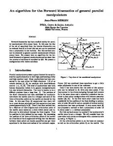
Let us consider the general 6 d.o.f parallel manipulators shown in figure 1. Two plates are connected through 6 articulated links. A linear actuator enables to change the link length and a linear sensor is used to measure this length. By controlling these lengths we are able to control the position and orientation of the upper-plate (the platform) with respect to the base plate. Usually the links are connected to the base by universal joints and to the platform by ball-and-socket joints. For a given posture of the mobile plate it is easy to find the corresponding links lengths. At the opposite finding the posture for a given set of links lengths i.e. solving the direct kinematics problem is difficult and there is usually not a unique solution. For example Lazard [6] has shown that for the most general case they cannot be more than 640 different postures. For some simplified designs it is well known that they can be up to 16 different postures [3, 4, 9]. In the case where both the platform and the base are planar a numerical resolution has been proposed in [8]. Using this numerical procedure we have found some sets of links lengths which yield to 12 real solutions i.e. 12 different postures of the platform. Recently some nu-
C B5
xr
Introduction
B3 B1
B6 B4 S joint U joint z A5
A1
A2
A3 A6 O
y
x A4
Figure 1: A parallel manipulator with 6 D.O.F.
merical procedures have been proposed for the most general case although no configuration with more than 12 solutions have been found [1, 11, 12]. But these procedures cannot be used to solve the direct kinematics problem in real time as they involve heavy computation. For real time purpose numerical iterative procedures have been proposed [7, 13]. Although these procedures are efficient some convergence problems may be encountered and faster procedures may be necessary, especially for using a dynamic model in real time. A practical solution may be to add extra sensors and to use this redundant information for decreasing the computation time. This approach has been used by Inoue [5] and Arai [2]. Arai added a passive link with 6 sensors to its design but found out that such a design increases the problem of link interference and that the measured position accuracy is poor. Our purpose is to determine how to add sensors to the manipulator to get a unique closed-form solution of the direct kinematics problem i.e. find their number and their location together with the procedure describing how to get the posture of the platform. A minimum number of sensors should be added in order to avoid any unnecessary extra hardware. To solve the direct kinematics problem it is sufficient to determine the coordinates in the base frame of 3 points of the platform. In this view it appears clearly that with 6 extra sensors data the posture of the mobile plate can be determined uniquely. Indeed let us assume that we add rotary encoders on the two revolute joints axis of the universal joint of 3 links of the robot (say links 1, 2, 3). For each of these links the measurements of the link length and the two angles of the joint enable to calculate the position of points B1 , B2 , B3 in the base frame and therefore solve our problem. But adding unnecessary sensor is a burden for the construction of a prototype. Therefore we propose various methods to solve this problem with less than 6 extra sensors. It will be then the choice of the designer to find the number of sensors enabling to get the best compromise between the supplementary cost and complexity of the manipulator (increasing with the number of sensors) and the computation time for solving the direct kinematics problem (decreasing with the number of sensors).
2
Various types of extra sensor data
Sensors can be added to a parallel manipulator in two different ways: • rotary sensor on the existing passive joints
• by adding passive links whose lengths are measured with linear sensor. Basically the first solution is better in view of the risk of links interference but may reduce the possible motion of the manipulator.
3
Adding sensors to the passive joints of the links
On each of these joints two sensors can be used to measure the direction of the link. With the link length it is then possible to calculate the position of the other extremity of the link. It is clearly equivalent from a geometrical view point to put these sensors either on the base or on the platform joints. We will assume that the sensors are added to the base joints. To determine a posture of the platform it is necessary and sufficient to know the positions of three points Bi , Bj , Bk of the mobile plate in the base frame. We will suppose that we have sensors measuring the links lengths and that we add sensors on the universal joints.
3.1
Measuring with four rotary sensors
We suppose that only the two universal joints of link 1 and 2 are equipped with their two sensors. Therefore we know the location of point B1 , B2 in the reference frame. We will show that by using the other sensory informations i.e. the four remaining links lengths, we will be able to determine the actual posture of the platform in most cases and find only two possible solutions in the worst case. As the location of points B1 , B2 is known the last remaining d.o.f. of the platform is a rotation around the line going through B1 , B2 . We consider now two others links say 3 and 4. As the mobile plate rotates around B1 , B2 points B3 , B4 will lie on circles. But these points must also lie on the spheres of center A3 , A4 whose radii are ρ3 , ρ4 , the lengths of links 3 and 4. Therefore these points lie at the intersection of the circles and the spheres i.e. there are two possible solutions for B3 (B31 , B32 ) and B4 (B41 , B42 ). But as all the B points belong to the same solid there are constraints on their relative position. To show that in general only one of the two positions of B3 satisfy all the constraints we project the problem in a plane perpendicular to the line going through B1 , B2 and denote by A3p the projection of A3 in this plane. We define a frame in the plane with origin the projection of B1 , B1p , the x-axis being defined by the line going through A3p . We denote by B3p , B4p the projections of points B3 , B4 in this plane (figure 2). As the mobile plate rotates around line B1 B2 point B3p lie on a
have δ2 = θ2 + λ − α = −θ1 + λ − α
B4
d4
Therefore equations (2), (3) will be simultaneously true only if: λ=α (4)
δ1
C4
A4p α
CA4
δ2
λ
d3
B3 θ1 B1p
(3)
A3p CA3
C3
Figure 2: In general the location of the mobile plate can be uniquely determined with only four extra sensors
Fortunately this equation will seldom be verified for all the last 4 remaining links. For example if we suppose that the Bi (i > 2) are coplanar (i.e. λ = 0) this equation will imply that the Ai will also be coplanar and that the line B1 B2 will lie in their plane. For example in figure 3) points B1 to B6 lie in the same plane PB , points A3 to A6 lie in the same plane PA and points B1′ to B6′ represent the alternative position of the mobile plate. PB B5
A1
circle C3 which center is B1p and radius d3 (the distance between point B3 and the line B1 B2 ) and B4p lie on a circle C4 which center is B1p and radius d4 (the distance between point B4 and the line B1 B2 ). As the position of points B3 , B4 must also satisfy the articular constraints B3p will also lie on a circle CA3 which center is A3p and B4p will also lie on a circle CA4 which center is A4p . Consequently the projected points of B31 , B32 , (B3p1 , B3p2 ), are the intersections of CA3 and C3 . Accordingly to the choice of the plane frame these points will be symmetrical with respect to the x-axis. Therefore if θ1 denotes the angle between the line B1p B3p1 and the x-axis the angle between the line B1p B3p2 will be −θ1 . For a fixed position of B3p the location of B4p is obtained from the the location of B3p by a rotation around B1p with a fixed angle λ. In a similar manner the projected points of B41 , B42 , (B4p1 , B4p2 ), are the intersections of CA4 and C4 . We will denote by α the fixed angle between the line B1p A4p and the x-axis and by δ1 , δ2 the angle between the the points B4p1 , B4p2 with the line B1p A4p . We have clearly δ2 = −δ1 . Let us suppose that a solution is given when the posture of the mobile plate is defined by the points B31 , B41 . Therefore in this posture B3p1 , B4p1 satisfy the geometric constraint of the mobile plate. We have therefore: δ 1 = θ1 + λ − α
(1)
δ2 = −δ1 = −θ1 − λ + α
(2)
and thus We investigate now if the posture defined by the points B32 , B42 satisfy also the geometric constraint. We
B1
B4
A6 B6
B3 A3 B2
A5
B4′ B3′
PA
A4 B5′ B6′
A2
Figure 3: An exception for the determination with four sensors : two solutions can be found. Proposition 1 With the lengths of the 6 legs and 4 sensors which measure the two angles of two different universal joints of the base we are able to determine uniquely the posture of the platform except in some particular configurations where two solutions can be found
3.2
Measuring with three rotary sensors
Let us suppose now that the joint of link 1 is fully equipped with two sensors and that the joint of link 2 has only one sensor. Therefore we know the location of point B1 and point B2 must lie on a circle centered in A2 , the normal to this circle being given by the sensor data α1 . As B2 is at a given distance from B1 it must also be on a sphere centered in B1 . Therefore point B2 is at the intersection of the sphere and the circle i.e. in general two solutions B21 , B22 can be found (figure 4).
According to the previous section one unique posture of the platform can be determined for a given set of points B1 , B2 . As point B1 is fixed and we known two possible locations of point B2 they will be at most two possible postures of the platform. We have not been able to determine if these two postures can both satisfy the others length constraints.
9 matrix. Nair shows that equation 6 can be written as: Aq = L (7) where A is a n x 16 matrix and q has dimension 16 x 1 and L n x 1, defined by: A q L
B22
B1
B21 2 A2 1
A1
α1
Figure 4: Measuring with three sensors. The sensor data on link 1 give the location of B1 and the sensor on link 2 enables to determine two possible locations for B2 Proposition 2 With two rotary sensors on the universal joint of one link and one rotary sensor on the universal joint of another link a maximum of two solutions can be found
4
˜ −1) − (CBri T ) W 2 ||OC|| T ˜ = (OC ROC R ) 2 = (||OAi ||2 + ||CBri ||2 − ρ2i )T
= ((OAi T )
Adding passive legs
A recent work presented by Nair [10] deal with a systematic study of the direct kinematics problem for a manipulator with n links. With the notation of figure 1 let us write the equation of the inverse kinematics. We have: AB = AO + OC + CB
CB = RCBr
(5)
where R = ((rij )) is the rotation matrix defining the orientation of the platform with respect to the base and CBr the coordinates of the articulation point in the platform frame. The length ρ of a link can be calculated by: ρ2 = ||AB||2 (6) ˜ = (r11 , r12 , r13 , r21 ....)T and W = (CBi .OAi )T Let R ˜R ˜ where W ˜ is a n x which can be written as W = W
Clearly equation (7) is a constrained linear system in the componants of q. Indeed not all componants of q are independent. The relations between these componants are called the closure equations and are listed by Nair. In order to solve the direct kinematics problem the linear part of equation (7) is solved and the result is reported in the appropriate closure equations. In some cases the resulting equations can be solved explicitly. A particular interesting case is the 9-legs planarplanar case where the articulations centers on the base and the platform are coplanar and 9 legs are connecting the base and the platform. In that case Nair shows that A is a 9 x 9 matrix as only two componants of ˜ play the vectors OC, ROC and four componants of R a role in the initial equations. The direct kinematics problem can then be solved explicitly if A has full rank. But Nair does not determine what are the geometries of the manipulator which insures that this condition is fulfilled. We will consider a special case of the 9-legs planarplanar case in which the platform is a triangle and the base is symmetrically shaped. Legs 1-6 are the actuated legs and legs 7-9 are the passive legs which meet at a unique point P on the platform (figure 5). In that case the rank of A will be 9 if: • the three points A7 , A8 , A9 are not collinear • P is not on the line joining B3 , B5 • point A4 has not the same y-coordinate as A3 • point A4 is not on the line joining the middle point of A1 , A2 to A3 • point P is not on the line joining B1 , B3 or the line joining B1 , B5 These exceptions are presented in figures 6,7. Proposition 3
A6 6
P 5 B5 A5
9
A5 A7 A4
base
A8
A6 A3
B3
4 A1
1
B1 8
A4 8
A9
9
7 A7
7
A1
A8
2 3 A2
A2 A3
Figure 5: A parallel manipulator with 6 D.O.F., 6 active legs and 3 passive legs.
Figure 7: Two geometries of the manipulator for which a unique solution to the direct kinematic problem cannot be found. For the 9-legs planar-planar case with three passive legs a unique solution for the direct kinematics can be found except for some special geometries of the manipulator. It must be noted that for the planar case with 8 legs Nair shows that even if the matrix A has full rank its methods yield to up to 8 different solutions and therefore cannot be used.
5
Figure 6: Three geometries of the manipulator for which a unique solution to the direct kinematic problem cannot be found.
Conclusion
We present the first result of theoretical investigation on solving the direct kinematic problem of parallel manipulators by adding a minimal number of extra sensors. We have investigated the case where sensors are added to the passive joints and have shown that in the most general case fours sensors will be sufficient to determine the actual posture of the manipulator. Then we have investigated the case where passive legs with measured length are added and shown that a minimum of three legs is necessary for a special case of parallel manipulator. We intend to study in the future what is the influence of sensor accuracy on the computation of the posture and the amount of computation needed for each method.
References [1] Angeles J. and Zanganeh K.E. The semigraphical solution of the direct kinematics of general platform manipulators. In ISRAM, pages 45– 52, Santa-Fe, November, 11-13, 1992.
[2] Arai T., Cleary K., and others . Design, analysis and construction of a prototype parallel link manipulator. In IEEE Int. Workshop on Intelligent Robots and Systems (IROS), volume 1, pages 205–212, Ibaraki, Japan, July, 3-6, 1990. [3] Charentus S. and Renaud M. Calcul du mod`ele g´eom´etrique direct de la plate-forme de Stewart. Research Report 89260, LAAS, Toulouse, France, July 1989. [4] Dedieu J-P and Norton G.H. Stewart varieties: a direct algebraic method for Stewart platforms. SigSam, 24(4):42–59, October 1990. [5] Inoue H., Tsusaka Y., and Fukuizumi T. Parallel manipulator. In Proc. 3rd ISRR, pages 321–327, Gouvieux, France, October, 7-11, 1985. [6] Lazard D. Stewart platform and Gr¨obner basis. In ARK, pages 136–142, Ferrare, September, 7-9, 1992. [7] Merlet J-P. Manipulateurs parall`eles, 3eme partie : applications. Research Report 1003, INRIA, March 1989. [8] Merlet J-P. An algorithm for the forward kinematics of general 6 d.o.f. parallel manipulators. Research Report 1331, INRIA, November 1990. [9] Merlet J-P. Direct kinematics and assembly modes of parallel manipulators. Int. J. of Robotics Research, 11(2):150–162, April 1992. [10] Nair P. On the kinematics geometry of parallel robot manipulators. Master’s thesis, Universit´e du Maryland, College Park, 1992. [11] Parenti-Castelli V. Recent techniques for direct position analysis of the generalized Stewart platform mechanism. In ARK, pages 129–135, Ferrare, September, 7-9, 1992. [12] Raghavan M. The Stewart platform of general geometry has 40 configurations. In ASME Design and Automation Conf., volume 32-2, pages 397– 402, Chicago, September, 22-25, 1991. [13] Reboulet C. Technique de la Robotique. Herm`es, Paris, 1988.