International Journal of Electrical, Electronics and Telecommunication Engineering, Vol. 43, Special Issue: 3
29
Closed Loop Speed Control of BLDC Motor with Fuzzy Controller under Different Operating Conditions A.PURNA CHANDRA RAO EEE Dept,Prasad V. Potluri Siddhartha Institute of Technology, Vijayawada Andhra Pradesh
[email protected]
Y.P.OBULESH EEE Department Lakireddy Bali Reddy College of Engineering, Mylavaram Andhra Pradesh
[email protected]
CH. SAI BABU EEE Department, Jawaharlal Nehru Technological University Kakinada, Kakinada Andhra Pradesh
[email protected]
ABSTRACT In the recent past, variable speed driving systems have sprouted in various small scale and large scale applications like automobile industries, domestic appliances etc. The usage of green and eco friendly electronics are greatly developed to save the energy consumption of various devices. This lead to the development in Brushless DC motor (BLDCM). The usage of BLDCM enhances various performance factors ranging from higher efficiency, higher torque in lowspeed range, high power density ,low maintenance and less noise than other motors. The BLDCM can act as an alternative for traditional motors like induction and switched reluctance motors. In this paper the simulation is carried out for 120 degree mode of operation. The test results shows that the performance of BLDCM which are highly acceptable. Finally a Fuzzy controller is applied for closed loop speed control under various loading conditions. Index Terms- Bipolar starting and unipolar starting drive, fuzzy control, 120 degree mode.
I INTRODUCTION Using of Permanent Magnet in electrical machines have so many benefits and advantages then electromagnetic excitation machines these are zero excitation losses result in high efficiency, simple construction, low cost less maintenance and high torque or high output power per unit volume . In early 19th century permanent magnet excitation system was used for first time in electrical machines. The performance of this machine was very poor due to poor quality of hard magnetic material make this less usable. After the invention of alnico invigorated the use of permanent magnet excitation system. Rare earth permanent magnets improve the power density and dynamic prformance of the machine. Induction motors are most popular machine in the 20th century due to its simple construction, less price, reasonable reliability and low maintenance. Due to small air gap, lower efficiency and low power factor than synchronous machine make synchronous machine prevalent in industrial applications. Due to high power to weight ratio, high torque, good
© RSJ 2012 RSJ ARCHIVES
dynamic control for variable speed applications, absence of brushes and commutator make Brushless dc (BLDC) motor, best choice for high performance applications. Due to the absence of brushes and commutator there is no problem of mechanical wear of the moving parts [2], [3]. As well, better heat dissipation property and ability to operate at high speeds [4] make them superior to the conventional dc machine. However, the BLDC motor constitutes a more difficult problem than its brushed counterpart in terms of modeling and control system design due to its multi-input nature and coupled nonlinear dynamics. Due to the simplicity in their control, Permanent-magnet brushless dc motors are more accepted used in high-performance applications. In many of these applications, the production of ripple-free torque is of primary concern. There are three main sources of torque ripple production in BLDCMs: cogging torque, reluctance torque, and mutual torque. Cogging torque is created by the stator slots interacting with the rotor magnetic field and is independent of stator current excitation. Reluctance torque is caused by the variation in phase inductance with respect to position. Mutual torque is created by the mutual coupling between the stator winding current and rotor magnetic field. In general, surface-mounted magnets are used in many highperformance BLDCM’s. Because the permeability of the magnet material is nearly equal to that of air, the effective air gap is enlarged by the magnet. This fact ensures minimum armature effect on the rotor field from the stator currents. If a BLDCM is designed with low saliency and either the stator slots or rotor magnets are skewed by one slot pitch, the effects of the first two torque components can be greatly reduced. Therefore, if the waveforms of the phase back EMF and phase current are perfectly matched, torque ripple is minimized and the mutual torque component is maximized.Conventionally, PI, PD and PID controller are most popular controllers and widely used in most power electronic closed loop appliances however recently there are many researchers reported successfully adopted Fuzzy Logic Controller (FLC) to become one of intelligent controllers to their appliances [3]. With respect to their successful methodology implementation. This kind of methodology implemented in this paper is using
International Journal of Electrical, Electronics and Telecommunication Engineering, Vol. 43, Special Issue: 3
fuzzy logic controller with feed back by introduction of voltage output respectively. The introduction of voltage output in the circuit will be fed to fuzzy controller to give appropriate measure on steady state signal. The fuzzy logic controller serves as intelligent controller for this propose. Fuzzy logic has rapidly become one of the most successful of today’s technology for developing sophisticated control system. With it aid complex requirement so may be implemented in amazingly simple, easily minted and inexpensive controllers. The past few years have witnessed a rapid growth in number and variety of application of fuzzy logic. The application range from consumer products such as cameras ,camcorder ,washing machines and microwave ovens to industrial process control ,medical instrumentation ,and decision- support system .many decision-making and problem solving tasks are too complex to be understand quantitatively however ,people succeed by using knowledge that is imprecise rather than precise . fuzzy logic is all about the relative importance of precision .fuzzy logic has two different meanings .in a narrow senses ,fuzzy logic is a logical system which is an extension of multi valued logic .but in wider sense fuzzy logic is synonymous with the theory of fuzzy sets . Fuzzy set theory is originally introduced by Lotfi Zadeh in the 1960,s[15] resembles approximate reasoning in it use of approximate information and uncertainty to generate decisions. Several studies show, both in simulations and experimental results, that Fuzzy Logic control yields superior results with respect to those obtained by conventional control algorithms thus, in industrial electronics the FLC control has become an attractive solution in controlling the electrical motor drives with large parameter variations like machine tools and robots. However, the FL Controllers design and tuning process is often complex because several quantities, such as membership functions, control rules, input and output gains, etc must be adjusted. The design process of a FLC can be simplified if some of the mentioned quantities are obtained from the parameters of a given Proportional-Integral controller (PIC) for the same application. In this paper finally closed loop speed control is done by using fuzzy logic controller under various loading conditions. II.
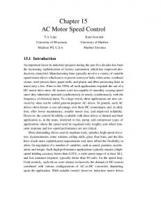
in unipolar mode. Shifting of modes between unipolar and bipolar operation is achieved based on speed requirement. The proposed inverter consists of 4 legs. The 3 phases of BLDC motor is connected to first 3 legs and neutral point is connected to the fourth leg as shown in Fig.1. In bipolar operation first 3 legs are active and the 4th leg is inactive. Here we have considered only bipolar operation.
Fig. 1 Proposed Inverter Circuit
Fig. 2 Free-wheeling of negative conducting B Phase
by switching on Q1 and Q4, phase A conducts in positive direction and phase B conducts in negative direction. By switching off Q4 and switching on Q6, a free-wheeling path is established through phase B, diode D3, switch Q1 and Phase A as shown in Fig. 2. By switching off Q1 and switching on Q3 and Q6, the free-wheeling energy in positive conducting phase A flows through resistor Rs, D2, phase A, phase C, and Q6, as shown in Fig. 3.
PRINCIPLE OF OPERATION
In conventional BLDC motor during bipolar operation, at any time across DC bus, two phases come in series. Only half of the DC bus voltage is applied to each phase, resulting in addition of torque constant on both phases there by achieving high starting torque. But speed will be limited. To get higher speed, full DC bus voltage is to be applied to each phase. This can be achieved in unipolar operation, where each phase conducts only in one direction which in turn reduces the starting torque. Thus in order to get high torque, motor should operate in bipolar mode and to get high speed motor should operate
© RSJ 2012 RSJ ARCHIVES
30
Fig. 3 Free-wheeling of positive conducting A phase
31
International Journal of Electrical, Electronics and Telecommunication Engineering, Vol. 43, Special Issue: 3
III MODELLING of BLDC MOTOR Modeling of a BLDC motor can be developed in the similar manner as a three phase synchronous machine. Since its rotor is mounted with a permanent magnet, some dynamic characteristics are different. Flux linkage from the rotor is dependent upon the magnet. Therefore, saturation of magnetic flux linkage is typical for this kind of motors. As any typical three phase motors, one structure of the BLDC motor is fed by a three phase voltage source as shown in Fig. 4. The source is not necessary to be sinusoidal. Square wave or other waveshape can be applied as long as the peak voltage is not exceeded the maximum voltage limit of the motor. Similarly, the model of the armature winding for the BLDC motor is expressed as follows.
½ Vdc R
L-M
R
L-M
Ea
Eb L-M
R
Ec
½ Vdc
Fig. 4 BLDC Motor Control System Ea Ia ωt
Eb
(1)
Ib
(2)
Ec Ic
(3) 30
60
90
120
150
180
210
240
270
300
330
360
Fig.5 BLDC Motor back emf and the motor phase currents
Or in the compact matrix form as follows.
(4)
The permanent magnet also influences produced torques due to the trapezoidal flux linkage. Given that KT is the torque constant. The produced torques
/ω
.
(8)
The resultant torque, TE, can be obtained by the following expressions. (9)
Where is the arma
(10)
M is the mutual inductance Armature resistance in ohm
(11)
Are the terminal phase voltages in volts (12) Motor input current in amperes
With the Newton’s second law of motion, the angular motion of the rotor can be written as follows.
Are the motor back emf in volts P in the matrix represents
(13) Due to the permanent magnet mounted on the rotor, its back emf is trapezoidal as shown in Fig. 5. The expression of back emf must be modified as expressed in
Where TL load torque in N-m J rotor inertia in [kgm2]
(5)
B damping constant
(6)
IV. FUZZY LOGIC CONTROLLER (7) Where KE is the back emf constant and ω is the mechanical speed of the rotor.
© RSJ 2012 RSJ ARCHIVES
FLC is one of the most successful applications of fuzzy set theory, introduced by Zadeh in 1965 [4]. Its major features are the use of linguistic variables rather than numerical variables. Linguistic variables, defined as variables whose values are sentences in natural language
International Journal of Electrical, Electronics and Telecommunication Engineering, Vol. 43, Special Issue: 3
32
(such as small and large) may be represented by fuzzy sets. A fuzzy set is an extension of a crisp set where an element can only belong to a set (full membership) or not belong to at all (no membership). Fuzzy set allow partial membership which means that an element may partially belong to more than one set. A fuzzy set A is characterized by a membership function that assigns to each object in a given class a grade of membership can range from 0 (no membership) to 1 (full membership), we therefore write
in this paper, one fuzzy controller have been designed, Fuzzy controller uses two inputs variables. Speed error e and derivative of e i.e. edot, derivative xdot .The proposed fuzzy logic controllers used to control the inverted pendulum uses conventional triangular membership functions. Furthermore, the fuzzy inference engine implements a set of IF-AND-THEN rules on the angle error e ,edot and output Fp and cart position error x, xdot and output Fc. All six universe of discourse are divided into three overlapping fuzzy set values labeled N (Negative), Z (Zero) and P (Positive).
Which means that the fuzzy set A belongs to a universal set X (usually called universe of discourse) defined in a specific problem. A fuzzy set A is called a fuzzy singleton when there is only one element xo with while all other elements have a membership grade which equal to zero. This approach allows characterization of the system behavior through simple relations (fuzzy rules) between linguistic variables. Usually, fuzzy rules are expressed in the form of fuzzy conditional statements Ri of the type.
Fig.7 shows three membership functions of pendulum angle controller. For cart position controller similar membership functions are defined for the universe of discourse x: [-0.5 0.5], xdot: [-0.03 0.03] and Fc: [-12 12]. Design of the rules are based on heuristic knowledge of the behavior and based on the theoretical criteria [7], [8]. To generate the rules for this work the basic criteria is considered as, if the pendulum is falling in one direction, then push the cart in the same direction to counter the movement of the pendulum. Nine rules are defined for each controller. The rule base matrix for pendulum angle controller is shown in Table I. Same rule base is taken for the,
Ri : if x is small THEN y is large Where x and y are fuzzy variables, and small and large arelabels of fuzzy set. If there are i =1 to n rules, the rule set isrepresented by union of these rules R=R1 else R2 else …Rn A fuzzy logic controller is based on a collection of R control rules. The execution of these rules is governed by the compositional rule of inference [5], [6]. The general structure of an FLC is represented in Fig.6 and comprises four principle components: 1) a fuzzification inference converts input data into suitable linguistic values; 2) a knowledge base consists of a data base with the necessary linguistic definitions and control rule set; 3) a decision making logic infers the fuzzy control action from the knowledge of the control rules and the linguistic variable definitions; 4) a defuzzification., inference yields a non fuzzy control action from an inferred fuzzy controlled action.
Fig. Membership Functions for e, edot, Fp
Fig: Block diagram representation of Fuzzy Logic Controller
© RSJ 2012 RSJ ARCHIVES
Fig. Rules for fuzzy logic controller
33
International Journal of Electrical, Electronics and Telecommunication Engineering, Vol. 43, Special Issue: 3
V. SIMULATION RESULTS Fig. 9 SIMULINK model of the converter block
The inputs of the converter block is speed, rotor position, back emfs and voltage, the output of the block is current. Here simulation is carried out for four cases. In case 1 BLDC with open loop control, Case 2 BLDC with Closed loop Fuzzy Control on No Load, Case 3 BLDC with Closed loop Fuzzy Control on Increasing Load, Case 4 BLDC with Closed loop fuzzy Control on Decreasing Load. Table I: The test parameters of the motor taken for simulation are given Fig. 6 SIMULINK model of BLDC motor
Fig.6 shows the Matlab/Simulink model of BLDC motor with closed loop control. This Model consists of four sub blocks named as torque – speed block, back emf block, converter block and torque block. fig. 7 shows the SIMULINK model of the Torque speed loop in the BLDC motor circuit. The input of the block is load torque and electromagnetic torque. The output of the block is the rotor angle and angular speed. .
Parameters
Value
Rated
1000 W
Power
Rated Voltage
100V
Resistance of the stator (R)
0.2ohm
Inductance of the stator (L) Moment of Inertia (J)
0.01H 0.01Kg-m/Sec2
Back emf constant (Kb)
0.5V/rad/s
Load Torque (TL )
1N-m
Motor Torque constant (Kt)
0.5N-m
No of Pole Pairs 4 A. Case 1-BLDC with open Loop Control 4
3
Fig: 7 SIMULINK model of the Torque speed loop
2.5
2
Speed in rpm
Fig.8 shows the Trapezoidal back emf block of the BLDC motor. The input of this block is angular speed and rotor angle, and output is back emf.
x 10
1.5
1
0.5
0 0
0.002
0.004
0.006
0.008
0.01 Time in sec
0.012
0.014
0.016
0.018
0.02
Fig. 10 Output waveforms of the speed of the motor
Fig. 10 shows the no load speed of the motor with open loop control. At no load with open loop control motor is achieving a speed of 25000 RPM. 3
2
Fig.8 Trapezoidal back emf loop of the BLDC motor
1
Back Emf
The below figure shows the SIMULINK model of the converter block in the BLDC motor.
0
-1
-2
-3
0
0.002
0.004
0.006
0.008
0.01 Time in sec
0.012
0.014
0.016
0.018
0.02
Fig.11 Back EMF of the BLDC motor
Fig. 11 shows the trapezoidal back emf wave form. Here we have considered 120 degree mode of operation.
© RSJ 2012 RSJ ARCHIVES
34
International Journal of Electrical, Electronics and Telecommunication Engineering, Vol. 43, Special Issue: 3
0.5
1.5 0.4 0.3
1
Currents in amps
0.2 0.1 0
0.5 -0.1
Back Emf
-0.2 -0.3 -0.4 -0.5
0
0.002
0.004
0.006
0.008
0.01 Time in sec
0.012
0.014
0.016
0.018
0.02
0
-0.5
Fig.12 Output waveforms of the currents. -1
Fig.12 shows the three phase currents of motor. Initially current is high, once the speed reaches steady value then the current will decreases. -4
6
-1.5
0
0.005
0.01
0.015 Time in sec
0.02
0.025
0.03
0.02
0.025
0.03
0.025
0.03
Fig.15:Back EMF of the BLDC motor
x 10
0.5
5
0.4 4 Torque N/m
0.3 3
0.2 0.1 Currents
2
1
0
0 -0.1 -0.2
0
0.002
0.004
0.006
0.008
0.01 Time in sec
0.012
0.014
0.016
0.018
0.02
-0.3
Fig.13 Output waveform of the torque of the motor
-0.4
Fig.13 shows the electromagnetic torque generated by the motor. Initially torque is high, once the speed reaches steady value torque will decreases.
-0.5
10000
4 Torque in N/m
5
Speed in rpm
2
4000
1
2000
0
0.005
0.01
0.015 Time in sec
0.02
0.025
0.03
Fig. 14 Output waveforms of the speed of the motor
Fig. 14 shows the no load speed of the motor with fuzzy control. Here reference speed is taken as 12000 rpm the motor reaches the reference speed very quickly with fuzzy control.
© RSJ 2012 RSJ ARCHIVES
0.015 ime in sec
x 10
3
6000
0
0.01
-4
6
12000
0
0.005
Fig.16 Output waveforms of the currents
B. Case 2-BLDC with Closed Loop fuzzy control on No Load
8000
0
0
0.005
0.01
0.015 Time in sec
0.02
Fig.17 Output waveform of the torque of the motor
Fig.17 shows the electromagnetic torque generated by the motor. Initially torque is high, once the speed reaches steady value torque will decreases since it is no load case so torque is small value equivalent to friction torque.
35
International Journal of Electrical, Electronics and Telecommunication Engineering, Vol. 43, Special Issue: 3
C. Case 3-BLDC with Closed Loop Fuzzy control for Increasing Load
-4
6
x 10
12000 5
10000 4 Torque in N/m
8000
speed in rpm
6000
3
2
4000
1
2000
0
0
-2000
0
0.002
0.004
0.006
0.008
0.01 Time in sec
0.012
0.014
0.016
0.018
0
Fig. 18 shows the speed of the motor with Fuzzy control. Here reference speed is taken as 12000 rpm the motor reaches the reference speed very quickly with Fuzzycontrol. Here load torque is increasing from 0.1 to 0.2 N-m at time t=0.01 sec. At this time there is a small decrease in the speed of the motor.
0.004
0.006
0.008
0.01 Time in sec
0.012
0.014
0.016
0.018
0.02
Fig.21 Output waveform of the torque of the motor
0.02
Fig. 18 Output waveforms of the speed of the motor
0.002
Fig.21 shows the electromagnetic torque generated by the motor. Initially torque is high, once the speed reaches steady value torque will decreases to rated value. At t=0.01 sec load torque is increased to double the value so Electromagnetic torque also increase by same percentage.
D. Case 4-BLDC with Closed Loop fuzzy control for Decreasing Load
1.5 12000
10000
1
8000
Speed in rpm
Back Emf
0.5 6000
4000
0 2000
-0.5
0
-2000
-1
0
0.002
0.004
0.006
0.008
0.01 Time in sec
0.012
0.014
0.016
0.018
0.02
Fig. 22 Output waveforms of the speed of the motor -1.5
0
0.002
0.004
0.006
0.008
0.01 Time in sec
0.012
0.014
0.016
0.018
0.02
Fig.19 Back EMF of the BLDC motor 0.5 0.4 0.3
Fig. 22 shows the speed of the motor with fuzzy control. Here reference speed is taken as 12000 rpm the motor reaches the reference speed very quickly with fuzzy control. Here load torque is decreasing from 0.2 to 0.1 Nm at time t=0.01 sec. At this time there is a small increase in the speed of the motor.
0.2
Current in amps
1.5 0.1
0
1 -0.1 -0.2
0.5
Back Emf
-0.3 -0.4 -0.5
0
0.002
0.004
0.006
0.008
0.01 Time in sec
0.012
0.014
0.016
0.018
0
0.02
-0.5
Fig.20 Output waveforms of the currents
Fig.20 shows the three phase currents of motor. Initially current is high, once the speed reaches steady value current will decreases to rated value. At t=0.01 sec load torque is increased to double the value so current also increase by same percentage.
© RSJ 2012 RSJ ARCHIVES
-1
-1.5
0
0.002
0.004
0.006
0.008
0.01 Time in sec
0.012
0.014
Fig.23 Back EMF of the BLDC motor
0.016
0.018
0.02
36
International Journal of Electrical, Electronics and Telecommunication Engineering, Vol. 43, Special Issue: 3
[2] G.H. Jang and M.G. Kim, “A Bipolar-Starting and Unipolar-Running Method to Drive an HDD Spindle Motor at High Speed with Large Starting Torque,” IEEE Transactions on Magnetics, Vol. 41, no.2, pp. 750-755, Feb. 2005.
0.5
0.4
0.3
Currents in amp
0.2
0.1
[3] E.Grochowski and R.F. Hyot,”Future trends in hard disk drives”,IEEE Tran. On Magnetics,vol.32,no.3,pp1850-1854,May 1996.
0
-0.1
-0.2
-0.3
-0.4
-0.5
0
0.002
0.004
0.006
0.008
0.01 Time in sec
0.012
0.014
0.016
0.018
0.02
Fig.24 Output waveforms of the currents
Fig.24 shows the three phase currents of motor. Initially current is high, once the speed reaches steady value, current will decreases to rated value. At t=0.01 sec load torque is decreased to half the value so current also decreased by same percentage. 6
x 10
4 Torque in N/m
[7] J.R.Hendershot and Miller,”Design of Brushless Permanent Magnet Motors, Oxford Univ. Press,1994
3
2
1
0
[5] S.X.Chen, M.A.Jabbar, O.D. Zhang and Z.J.Lie,”New Challenge: Electromagnetic design of BLDC motors for high speed fluid film bearing spindles used in hard disk drives”,IEEE Trans. Magnetics ,vol32,no.5, pp38543856,Sep. 1996. [6] T.Kenzo and S. Nagamori, Permanent Magnets and Brushless DC Motors, Tokyo,Japan,Sogo Electronics,1984.
-4
5
0
[4] J.D.Ede, ,Z.Q.Zhu and D.Howe,”Optimal split ratio control for high speed permanent magnet brushless DC motors”, in Proc.5th Int,Conf..Electrical Machines and Sytems’,vol.2,Aug 2001,pp 909-912
0.002
0.004
0.006
0.008
0.01 Time in sec
0.012
0.014
0.016
0.018
0.02
Fig.25 Output waveform of the torque of the motor
Fig.25 shows the electromagnetic torque generated by the motor. Initially torque is high, once the speed reaches steady value torque will decreases to rated value. At t=0.01 sec load torque is decreased to half the value so Electromagnetic torque also decreases by same percentage.
V. CONCLUSION Permanent-magnet brushless dc motors is more widely used in high-performance applications because of their higher efficiency, higher torque in low-speed range, high power density ,low maintenance and less noise than other motors. In this paper closed loop speed control of BLDC is carried out using fuzzy controller and the simulation results are presented for the performance of the motor. The results show that the dynamic performance of the motor is quite satisfactory. Simulation results are shown for various loading conditions.
REFERENCES [1] R. Civilian, and D. Stupak, "Disk drive employing multi mode spindle drive system," US patent 5471353, Oct 3, 1995.
© RSJ 2012 RSJ ARCHIVES
[8] S.W.Cameron.”Method and apparatus for starting a sensorless polyphase dc motors in dual coil mode and switching to single coil mode at speed”, U.S.Patent 5455885,, Nov.28,1995 [9] T.Gopalaratnam and H.A.Toliyat, “A new topologyfor unipolar brushless dc motor drives”,. IEEE TransPower Electronics, vol.18,No.6, pp 13971404,Nov.2003. [10] Bhim Singh and Sanjeev Singh, “State of art on permanent magnet brushless Dc motor Drives”, Journal of Power Electronics”, vol.9 no.1 pp 1-17 Jan.2009. [11] Maxon Precision http://www.maxonmotor.com.
Motors
Inc.,
AUTHORS PROFILE A.PURNA CHANDRA RAO received the B.E (Electrical and Electronics Engineering) degree from Andhra University, Visakhapatnam, India, M.Tech degree from Jawaharlal Nehru Technological University, Anantapur, India in 1998 and 2004 .He is currently working as an Associate Professor in the Dept. of Electrical and Electronic Engineering, at Rao & Naidu Engineering College, Ongole. His area of interest is Power Electronics, and Electrical Drives.
International Journal of Electrical, Electronics and Telecommunication Engineering, Vol. 43, Special Issue: 3
Y. P. OBULESU received his B.E degree in Electrical Engineering from Andhra University, Visakhapatnam, India, M.Tech degree from Indian Institute of Technology, Kharagpur, India, in 1996 and 1998. He received his PhD degree from Jawaharlal Nehru Technological University, Hyderabad, in 2006. He has published several National and International Journals and Conferences. His area of interest is the simulation and design of power electronics systems, DSP controllers, fuzzy logic and neural network application to power electronics and drives.
CH. SAI BABU received the B.E from Andhra University (Electrical & Electronics Engineering), M.Tech in Electrical Machines and Industrial Drives from REC, Warangal and PhD in Reliability Studies ofHVDC Converters from JNTU, Hyderabad. Currently he is working as a Professor in Dept. of EEE in JNTUCEK, Kakinada. He has published several National and International Journals and Conferences. His area of interest is Power Electronics and Drives, Power System Reliability, HVDC Converter Reliability, Optimization of Electrical Systems and Real Time Energy Management.
© RSJ 2012 RSJ ARCHIVES
37