Iraq J. Electrical and Electronic Engineering Vol.10 No.2 , 2014
اﻟﻤﺠﻠﺔ اﻟﻌﺮاﻗﻴﺔ ﻟﻠﻬﻨﺪﺳﺔ اﻟﻜﻬﺮﺑﺎﺋﻴﺔ واﻻﻟﻜﺘﺮوﻧﻴﺔ 2014 ، 2 اﻟﻌﺪد، 10 ﻡﺠﻠﺪ
Speed Control of BLDC Motor Based on Recurrent Wavelet Neural Network Adel A. Obed,
Ameer L. Saleh
Department of Electrical Engineering College of Engineering University of Basrah
[email protected]
Department of Electrical Engineering College of Engineering University of Basrah
[email protected]
Abstract
In recent years, artificial intelligence techniques such as wavelet neural network have been applied to control the speed of the BLDC motor drive. The BLDC motor is a multivariable and nonlinear system due to variations in stator resistance and moment of inertia. Therefore, it is not easy to obtain a good performance by applying conventional PID controller. The Recurrent Wavelet Neural Network (RWNN) is proposed, in this paper, with PID controller in parallel to produce a modified controller called RWNN-PID controller, which combines the capability of the artificial neural networks for learning from the BLDC motor drive and the capability of wavelet decomposition for identification and control of dynamic system and also having the ability of self-learning and self-adapting. The proposed controller is applied for controlling the speed of BLDC motor which provides a better performance than using conventional controllers with a wide range of speed. The parameters of the proposed controller are optimized using Particle Swarm Optimization (PSO) algorithm. The BLDC motor drive with RWNN-PID controller through simulation results proves a better in the performance and stability compared with using conventional PID and classical WNN-PID controllers. Index Terms: BLDC motor, modeling and simulation, Recurrent WNN, PSO algorithm
I. INTRODUCTION Recently, the BLDC motor becomes the fastest growing and most demand in many applications such as, industrial automation, medical, aerospace, consumer, electric traction, road vehicles, aircraft, etc. It has an advanced advantages such as high reliability, high power density, lower weight, good efficiency. Moreover, it has good mechanical properties and speed performance compared with DC motor [1,2]. There are no brushes in the BLDC motor like the DC motor. Instead they are electronically commutated using three phase inverter with feedback rotor position. The rotor position feedback is used for starting and providing proper commutation to turn on the inverter. BLDC motor is actually a permanent magnet synchronous motor (PMSM) with trapezoidal back emf. The BLDC motor consists of permanent magnet rotor and distributed stator winding. The stator has three phase windings and each winding is displaced by 120 , the winding are distributed to produce trapezoidal back emf.
118
The BLDC motor is operated when two phases are ON at any time while the third phase is floating. When the two phases are energized depend on the rotor position, the torque will produced by the interaction between the magnetic field generated by the stator coils and the permanent magnets rotor[3]. The industries development requires more accurate, faster response, more efficient, therefore, motor speed control system is essential. Conventional PID controller is simple, stable and easy adjustment. But in most industrial processes with different degrees of nonlinear, parameter variability and uncertainty of mathematical model of the system, tuning PID controller parameters is difficult, poor robustness, therefore, it's difficult to achieve the optimal state under field conditions in the actual production. In this paper, the recurrent wavelet neural network is proposed with PID controller in parallel to produce an improve controller called RWNN-PID controller. The proposed controller is used to control the duty cycle of the DC-
Iraq J. Electrical and Electronic Engineering Vol.10 No.2 , 2014
اﻟﻤﺠﻠﺔ اﻟﻌﺮاﻗﻴﺔ ﻟﻠﻬﻨﺪﺳﺔ اﻟﻜﻬﺮﺑﺎﺋﻴﺔ واﻻﻟﻜﺘﺮوﻧﻴﺔ 2014 ، 2 اﻟﻌﺪد، 10 ﻡﺠﻠﺪ
DC converter which gives the source voltage for PWM inverter while the rotor position scheme is used for firing the gates and to provide the proper commutation sequence to the inverter. The DCDC converter method is the best solution in applications where torque ripples and switching losses is minimized. The proposed controller is used to control the speed of BLDC motor to provide better performance than the conventional controller methods. In addition, the particle swarm optimization (PSO) algorithm is used for learning the parameters of the RWNN-PID controller. .
where , , are the phase voltages, , , are the phase stator currents, is the stator resistance per phase; is the stator self inductance and M is the mutual inductance. The stator currents are considered to be balanced, i.e. + + =0
(4)
Equations (1-3) can be modified as follow: +
+ (5)
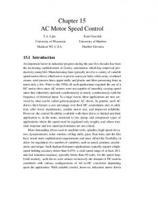
II. MATHEMATICAL MODEL OF BLDC MOTOR There are three stator windings and permanent magnets on the rotor. Since both the magnet and the stainless-steel retaining sleeves have high resistivity, rotor-induced currents can be neglected and no damper windings are modeled. Hence the circuit equations of the three windings are in phase variables. The mutual inductance between the stator and the rotor has a trapezoidal shape which produces a trapezoidal back emf in stator winding[1-6]. Figure(1) shows the equivalent circuit of a three-phase, Yconnected BLDC motor driven by a three phase inverter.
+ (6) The back–emf is a function of rotor position. It has 120º phase angle difference so equation of each phase should be as follows: (7) (8)
Three phase inverter
(9)
+
S1
D1 S3
D3 S5
D5
a b
VDC
D2 S4
R
L
R
L
ea
eb
R
c S2
Model of BLDC Motor
D4
S6
L
Rotor position sensor
ec
D6
-
where is the rotor speed, is the back-emf constant and is the electrical rotor angle. The electrical rotor angle equals to mechanical rotor angle multiplied by the number of poles P:
Controller
(10)
Fig.(1) Equivalent circuit of BLDC motor drive
And
The stator line voltage equations can be written as = R( - ) + (L-M)
( - )+
=∫ (11) The function gives the trapezoidal waveform of the back-emf. A period of 2 of this function can be written as follow:
(1)
= R( - ) + (L-M)
( - )+
(2)
= R( - ) + (L-M)
( - )+
(3)
119
Iraq J. Electrical and Electronic Engineering Vol.10 No.2 , 2014
1 6 π
1
θ
˂θ ˂ π
θ
1 1
6 π
θ
The developed torque kt
[ θ
θ
π
˂θ ˂π
π
˂ θ ˂ 5π ˂θ ˂
energized and phase C is freewheeling through diode D6. When the diode current is nonzero, the line voltages are , 0 and , and when the diode current has reached zero, the voltages and will have a different value which depends on the back emf's. Therefore, in on period phases A and B carry current and C phase is open, and *For ≠ 0
π
π
5π
اﻟﻤﺠﻠﺔ اﻟﻌﺮاﻗﻴﺔ ﻟﻠﻬﻨﺪﺳﺔ اﻟﻜﻬﺮﺑﺎﺋﻴﺔ واﻻﻟﻜﺘﺮوﻧﻴﺔ 2014 ، 2 اﻟﻌﺪد، 10 ﻡﺠﻠﺪ
(12)
π
can be expressed as 2π
θ
4π
(13) (15)
where is the torque constant. The developed torque, load torque and output power are related as follows:
*For
0
(14) where is the load torque; J is the rotor inertia and is the friction constant.
(16)
III. MODELLIING OF THREE –PHASE INVERTER Basically the principle operation of BLDC motor depends on the electronically commutation and the electronic commutation function is accomplished by opening and closing the six inverter switches according to the six-steps sequence[2]. The current in the two energized phases can be turned on and off any time during the 60° interval. It will be shown below that the output voltages of the inverter not only depend on the dc-source voltage and the rotor position, but also on the value of the back emf's and whether the phases currents are zero or nonzero[4,7]. Figure(2) shows how the inverter in Fig.(1) looks like during the first 60° interval when the switches are fired according to the required sequence. A phase current that is being turned off will flow through a freewheeling diode while the current in the phase that is being turned on is rising from zero. Which phase current is decaying and which one is rising depends on the rotor position. Two topologies can be considered according to the six intervals, the first topology is for the intervals (0-60), (120-180) and (240-300) as shown in Fig.(3a) while the second topology is for the intervals (60-120), (180-240) and (300360) as shown Fig(3b). The commutation period for the first 60 is when the switches in phase A and phase B are
To complete the mathematical model of the inverter must be complete the mechanical cycle. A
C
B
Vs
D6
0-60
Fig.(2) Circuit configuration during the first 60 interval
.a
e1
Z
e3
Z
.c
Z i3
i1
Vs
e2
Vd3
.
b
(a)
.a
e1
e3
Z
Z
.c
Z Vs
i3
i1 e2
Vd3
.
b
(b)
Fig.(3a,b) The circuit topologies from Fig.(1)
120
Iraq J. Electrical and Electronic Engineering Vol.10 No.2 , 2014
IV. WAVELET NEURAL NETWORKS A. Structure of Wavelet Neural Networks Wavelet neural networks (WNNs) is the combination of wavelet theory and neural networks. The structure of (WNN) is similar to that of neural network. It represents a feedforward neural network, taking one or more inputs, with one hidden layer and output layer. The hidden layer consists of neurons, whose activation functions are drawn from a wavelet basis. These wavelet neurons are usually referred to as wavelons, whose input parameters include the wavelet dilation (a) and translation (b) coefficients [8,9]. In wavelet neural networks, both the position (translation) and the dilation are optimized besides the weights. The structure of WNN is shown in Fig.(4). This network approximates any desired signal f(t) by generalizing a linear combination of a set of daughter wavelets where are generated by dilation(a) and translation(b) from mother wavelet as follows: (
)
1
The output of the wavelet neural network is given by: ∑
1
where is the weight of the node in hidden layer to the output unit, are the dilation factor and translation factor respectively, x is the input of the network, is the wavelet function. In this paper, the Mexican hat wavelet is used as the wavelet function, which is given as follows: 1 1 The network parameters can be optimized by any optimization technique [9-11]. This paper uses the particle swarm optimization
اﻟﻤﺠﻠﺔ اﻟﻌﺮاﻗﻴﺔ ﻟﻠﻬﻨﺪﺳﺔ اﻟﻜﻬﺮﺑﺎﺋﻴﺔ واﻻﻟﻜﺘﺮوﻧﻴﺔ 2014 ، 2 اﻟﻌﺪد، 10 ﻡﺠﻠﺪ
Fig.(4) Structure of wavelet neural network
B. Recurrent Wavelet Neural Networks (RWNN) In RWNN networks, the output depends not only on the current input of the network, but also on the previous outputs or states of the network. Therefore, the recurrent networks are more powerful than other non-recurrent networks and have important applications in nonlinear control and system identification. The feedback can be obtained by connecting signal from the output layer to the input layer or in one layer which is called partially feedback, or by state feedback in which each layer has feedback connection from the output to the input and also feedback from output to the input network. This type is called fully feedback connection. The wavelet network input consists of delayed samples of the system input and the system output y(t) as shown in Fig.(5). The number of inputs to the wavelet network increases with the order of the system being modeled. Hence, the output for each layer can be computed as [12,13]: )
(
The inputs of this layer for time t can be denoted as: 1 1 where, denotes the weight of the self-feedback loop. The network output is then:
(PSO) for minimizing the speed error according to a fitness function, when it runs online with BLDC motor drive as will be explained later.
∑
121
(
)
Iraq J. Electrical and Electronic Engineering Vol.10 No.2 , 2014
اﻟﻤﺠﻠﺔ اﻟﻌﺮاﻗﻴﺔ ﻟﻠﻬﻨﺪﺳﺔ اﻟﻜﻬﺮﺑﺎﺋﻴﺔ واﻻﻟﻜﺘﺮوﻧﻴﺔ 2014 ، 2 اﻟﻌﺪد، 10 ﻡﺠﻠﺪ
particles. When the neighborhood of a particle is the entire swarm, the best position in the neighborhood is referred to as the global best position of the particle and the resulting algorithm is referred to as the global best position PSO. Where the best previous position (giving the minimum fitness value) of any particle is called local best position (lbest). The index of the best particle among all particles in the population is called global best position (gbest). When smaller neighborhoods are used, the algorithm is generally referred to as the lbest PSO. The performance of each particle is measured using a fitness function that varies depending on the optimization problem. The objective functions considered are based on the desired criterion. The most common performance criteria that based on the error criterion are Integrated Absolute Error (IAE), Integrated of Time weight Square Error (ITSE) and Integrated of Square Error (ISE) that can be evaluated analytically in frequency domain. The selection of the criteria depends on the system and the controller. For a multidimensional problem, the velocity and position of each particle in the swarm are updated using the following equations:
where x: the desired signal, N: the number of neuron in the hidden layer, : the output weight, : the number of delay for the input and output network and the weight of the output feedback loop.
Fig.(5) Structure of recurrent wavelet neural network
C. Algorithm for Particle Swarm Optimization Technique Particle swarm optimization (PSO) is a population based on computational technique inspired from the simulation of social behavior (social-psychological theory) bird flocking, fish schooling and swarm theory. PSO was originally designed and developed by Eberhart and Kennedy [14]. PSO technique is derived from research on swarm such as fish schooling and bird flocking. According to the research results for a flock of birds, birds can find food by flocking (not by each individual). Thus, each companion called particle in the population, which is called swarm intelligence. PSO algorithm is one of the evolutionary computation methods for solving optimization problems. The method can be applied to control the speed control of BLDC motor that includes constraints without the graduate of the objective function. In a PSO algorithm, a swarm of individuals (called particles) fly through the search space. Each particle represents a candidate solution to the optimization problem. The position of a particle is influenced by the best position visited by itself i.e. its own experience and the position of the best particle in its neighborhood experience of neighboring
l g
s
s 4 (25)
where, , are the instant position and speed of particle i at iteration k respectively, w is the inertia weight, and are the acceleration constants and , represent a random variables between 0 and 1. (26)
where, and are the initial and final weights, iter is the current iteration time and is the maximum number of iterations[1417].
122
Iraq J. Electrical and Electronic Engineering Vol.10 No.2 , 2014
اﻟﻤﺠﻠﺔ اﻟﻌﺮاﻗﻴﺔ ﻟﻠﻬﻨﺪﺳﺔ اﻟﻜﻬﺮﺑﺎﺋﻴﺔ واﻻﻟﻜﺘﺮوﻧﻴﺔ 2014 ، 2 اﻟﻌﺪد، 10 ﻡﺠﻠﺪ
In this paper, a multi-objective function is used to find the optimal solution with a minimum speed error based on the Integral of Squared Error (ISE) criterion and overshoot ( criterion as follow: Fitness function = min(ISE)+min(
(27)
Where ∫
(28) (29)
e(i)=
(30)
where n is the actual speed, and is the desired speed of BLDC motor. According to the above, the PSO algorithm can be given in a flow chart as shown in Fig.(6).
V. SPEED CONTROL OF BLDC MOTOR BASED RWNN CONTROLLER The drive system consists of the controlled BLDC motor by three phase inverter, DC-DC converter (chopper) and the proposed RWNNPID controller. The rotor speed is directly proportional to the three-phase stator voltage. The strategy of the voltage control used DC-DC converter connected at the input of a PWM inverter [18]. The three-phase invertor can be implemented by a combinations of look up tables that takes the values of DC link voltage and the control signals from the control block. The proposed control system consists of rotor position scheme, which detect the rotor speed, to provide proper commutation signals to the gates of the inverter and recurrent WNN-PID controller to control the duty cycle of the DC-DC converter. The RWNNPID controller based on particle swarm optimization (PSO) is used to control the speed of BLDC motor in wide range and to provide better performance than conventional PID controller and using classical WNN-PID controller. Figure (7) shows the block diagram of the BLDC motor with classical WNN-PID controller based on PSO training algorithm.
Fig.(6) General flow chart of PSO
123
Iraq J. Electrical and Electronic Engineering Vol.10 No.2 , 2014
اﻟﻤﺠﻠﺔ اﻟﻌﺮاﻗﻴﺔ ﻟﻠﻬﻨﺪﺳﺔ اﻟﻜﻬﺮﺑﺎﺋﻴﺔ واﻻﻟﻜﺘﺮوﻧﻴﺔ 2014 ، 2 اﻟﻌﺪد، 10 ﻡﺠﻠﺪ
VI. SIMULINK IMPLEMENTATION FOR BLDC MOTOR SPEED CONTROL BASED ON A PROPOSED RWNNPID CONTROLLER The complete Simulink model of BLDC motor drive system is shown in Fig.(8). The BLDC motor can be built in Matlab according to the mathematical modeling given in equations [1-14]. The inverter can be implemented by a combination of look up tables according to the details given in section (3). The proposed RWNN consist of three layers, with two inputs in the input layer; the speed error and the change of this error. The hidden layer has four neurons with Mexican-hat wavelet function. One output in the output layer and feedback connection from the output for each layer. The feedback is used here called "Fully feedback". In addition, the RWNN contains a number of delays samples in the system input and the system output as shown in Fig.(9).
The translation and dilation factors, weights connection for WNN and PID parameters are tunning on-line using PSO algorithm. The PSO algorithm contents are given in Table(1). The speed is controlled by controlling the amplitude of the motor. This voltage is driven by DC-Dc converter and this converter is controlled by a PWM signal which is compared with the output of the RWNN-PID controller. Figure (11) and (12) show the Simulink model of speed control strategy and the DC-Dc converter respectively. Table(1): PSO Particle contents
PSO_Parameter Size of the swarm " no of birds " Maximum iteration number Dimension PSO parameter 𝑐 PSO parameter W W
Value 50
Fig.(7) Block diagram of the BLDC motor with WNN-PID controller based on PSO algorithm
124
50 15 1.2 1.2 0.9 0.3
Iraq J. Electrical and Electronic Engineering Vol.10 No.2 , 2014
اﻟﻤﺠﻠﺔ اﻟﻌﺮاﻗﻴﺔ ﻟﻠﻬﻨﺪﺳﺔ اﻟﻜﻬﺮﺑﺎﺋﻴﺔ واﻻﻟﻜﺘﺮوﻧﻴﺔ 2014 ، 2 اﻟﻌﺪد، 10 ﻡﺠﻠﺪ
Fig.(8) Simulink model of BLDC motor drive
Fig.(9) Simulink model of the proposed scheme of RWNN-PID controller
125
Iraq J. Electrical and Electronic Engineering Vol.10 No.2 , 2014
اﻟﻤﺠﻠﺔ اﻟﻌﺮاﻗﻴﺔ ﻟﻠﻬﻨﺪﺳﺔ اﻟﻜﻬﺮﺑﺎﺋﻴﺔ واﻻﻟﻜﺘﺮوﻧﻴﺔ 2014 ، 2 اﻟﻌﺪد، 10 ﻡﺠﻠﺪ
Fig.(10) Simulink model of speed control strategy
Fig.(12)Step change in speed under all conditions
Fig.(11) Simulink model of DC-DC converter
VII. SIMULATION RESULTS FOR RECURRENT WNN-PID CONTROLLER The BLDC motor drive system with RWNN-PID controller is implemented in Simulink/Matlab program, version 2012b which uses the 4 order Runge-Kutta-Gill method for Simulink setting. The simulation period that assumed in this model is 1sec. Figure(12) shows the speed response of the BLDC motor due to change in reference speed. The motor is driven at 500 rpm and the reference speed increases 500 rpm each 0.2sec. The motor speed follows the reference with a good response. Figure(13) shows the speed response for a direct starting two 2000 rpm with no load condition, and a sudden torque of 2N.m(Full load) is added at t=0.4sec. The developed torque during no load and load condition is shown in Fig.(14). Figures(15-18) show phase A current, phase A back emf voltage, line voltage( ) and the rotor position signal respectively for the same starting and loading conditions.
Fig.(13) Speed response under all conditions
Fig.(14) Development torque under all conditions
126
Iraq J. Electrical and Electronic Engineering Vol.10 No.2 , 2014
اﻟﻤﺠﻠﺔ اﻟﻌﺮاﻗﻴﺔ ﻟﻠﻬﻨﺪﺳﺔ اﻟﻜﻬﺮﺑﺎﺋﻴﺔ واﻻﻟﻜﺘﺮوﻧﻴﺔ 2014 ، 2 اﻟﻌﺪد، 10 ﻡﺠﻠﺪ
Fig.(15) Phase A current of BLDC motor Fig.(18) Rotor position signal of BLDC motor
Table (2) illustrates a comparison among RWNPID, WNN-PID and conventional PID schemes as speed controller in terms of performance. The comparison includes the calculation of speed rising time, settling time, steady state error and overshoot. This comparison shows that the RWNN-PID is the best method to overcome the nonlinearity in this drive with high relibility, more robust and good performance than the other methods as can be shown in Fig.(19) with no load and load conditions.
Fig.(16) Phase A back-emf voltage of BLDC motor
Table(2): comparision in performance
Performance RWNNPID Rise 0.0038 time(Sec) Settling 0.04 time(Sec) Steady state 2*1 % error Overshoot Approx.0% Fig.(17) Line voltage(
) of BLDC motor
127
WNNPID 0.0035
0.003
0.03
0.01
3*1
PID
% 2.5*1
0.12%
Approx. 0%
4
%
Iraq J. Electrical and Electronic Engineering Vol.10 No.2 , 2014
اﻟﻤﺠﻠﺔ اﻟﻌﺮاﻗﻴﺔ ﻟﻠﻬﻨﺪﺳﺔ اﻟﻜﻬﺮﺑﺎﺋﻴﺔ واﻻﻟﻜﺘﺮوﻧﻴﺔ 2014 ، 2 اﻟﻌﺪد، 10 ﻡﺠﻠﺪ
IX. CONCLUSION In this paper, the recurrent wavelet neural network (RWNN) is used with PID controller in parallel to produce modified controller called RWNN-PID controller. Particle swarm optimization technique is applied for tuning all the parameters of RWNN and PID controllers. With the use of the proposed RWNN-PID controller in speed control of BLDC motor drive, the speed response shows improvement in overshoot, rising time, settling time and steady state error. Moreover, the drive provides a flexible and robust due to effect of changes in motor parameters. Fig.(19) Speed response under no load and load conditions in different methods
VIII. ROBUSTNESS In order to test the robustness of the proposed method, the effect of changes in the stator resistance and inertia J on the speed response during no load and loading conditions is investigated here. The variation of stator resistance the moment of inertia will happen over time due to of the continuous work at high temperature and working conditions is not suitable. Figure(20) shows the effect of changes in the resistance and inertia compared with normal R and J. The RWNN-PID controller gives good response in speed with robustness during disturbances in R and J.
X. REFERENCES [1] A. Tashakori , M. Ektesabi and N. Hosseinzadeh, "Modeling of BLDC Motor with Ideal Back-EMF for Automotive Applications, Proceedings of the World Congress on Engineering, Vol.2, July 2011, PP.1-5. [2] Neethu U. and Jisha V. R., "Speed Control of Brushless DC Motor: A Comparative Study", IEEE International Conference on Power Electronics, Drives and Energy Systems, Dec., 2012, PP.1-5. [3] Padmaraja Yedamale, “Brushless DC (BLDC) Motor Fundementals”, AN885, 2003 Microchip Technology Inc. [4] S. Rambabu, "Modeling and Control of A Brushless DC Motor", Master Thesis in Power Control and Drives Technology, National Institute of Technology Rourkela, 2007. [5] Pillay P., Krishnan R., "Modeling, Simulation, and Analysis of Permanent-Magnet Motor Drives. II. The Brushless DC Motor Drive", IEEE Transactions on Industry Applications, Vol.2, Apr. 1989, PP. 247-279. [6] C. Gencer and M. Gedikpinar, "Modeling and Simulation of BLDCM Using Matlab/Simulink", IEEE Journal of Applied Sciences, Technology, Vol.6, 2006, PP. 688-691. [7] Dhiraj Ahuja and Sunil Kumar, "Adaptive Fuzzy Wavelet Network Control Design for Nonlinear Systems",International Journal of Advanced Technology& Engineering Research (IJATER), Vol. 3, Jan. 2013, PP. 1046-1054.
Fig.(20) Effect of changes in the resistance and inertia on the speed response
128
Iraq J. Electrical and Electronic Engineering Vol.10 No.2 , 2014
[8] Maohua Zhang, Changliang Xia, Yang Tian, Dan Liu, Zhiqiang Li, "Speed Control of Brushless DC Motor Based on Single Neuron PID and Wavelet Neural Network", IEEE International Conference on Control and Automation Guangzhou, China, June 2007. [9] Wissam Hassouneh, "Modeling and Control of Nonlinear Systems Using Wavelet Networks", Master Thesis of Engineering, American University of Sharjah School, 2006, PP. 148-157. [10] Sung Jin Yoo, Jin Bae Park, and Yoon Ho Choi, "Direct Adaptive Control Using Self Recurrent Wavelet Neural Network Via Adaptive Learning Rates for Stable Path Tracking of Mobile Robots", IEEE, American Control Conference, Proceedings of the 2005, Vol.1, June2005, PP.2848-2852. [11] Sung Jin Yoo, Yoon Ho Choi, and Jin Bae Park, "Generalized Predictive Control Based on Self-Recurrent Wavelet Neural Network for Stable Path Tracking of Mobile Robots: Adaptive Learning Rates Approach", IEEE Tansactions on Circuits and SystemsI, Vol.53, June 2006, PP.288-293. [12] Alberto A. Portillo, Michael Frye, Chunjiang Qian, "Particle Swarm Optimization for PID Tuning of a BLDC Motor", IEEE International Conference on Systems, Man, and Cybernetics, Oct. 2009. [13] Yogendra Kumar Soni1 and Rajesh Bhatt, "BF-PSO optimized PID Controller design using ISE, IAE, IATE and MSE error criteria", International Journal of Advanced Research in Computer Engineering & Technology (IJARCET), Vol.2, July 2013, PP. 1381-1394.
اﻟﻤﺠﻠﺔ اﻟﻌﺮاﻗﻴﺔ ﻟﻠﻬﻨﺪﺳﺔ اﻟﻜﻬﺮﺑﺎﺋﻴﺔ واﻻﻟﻜﺘﺮوﻧﻴﺔ 2014 ، 2 اﻟﻌﺪد، 10 ﻡﺠﻠﺪ
[14] Mohammad Sadegh Rahimian and Kaamran Raahemifar, "Optimal PID Controller Design for AVR System Using Particle Swarm Optimization Algorithm", IEEE, 24th Canadian Conference on Electrical and Computer Engineering (CCECE), May 2011, PP.3917-3922. [15] Taeib Adel, Ltaeif Ali, Chaari Abdelkader, "A PSO Approach for Optimum Design of Multivariable PID Controller for nonlinear systems", International Conference on Control, Engineering & Information Technology (CEIT'13) Proceedings Engineering & Technology, Vol.2, 2013, PP.2333-2336. [16] Bhim Singh, Vashist Bist, "A Single Sensor Based PFC Zeta Converter Fed BLDC Motor Drive for Fan Applications", Power India Conference, 2012 IEEE Fifth, Dec.2012, PP.337340. [17] Taeib Adel, Ltaeif Ali, Chaari Abdelkader, "A PSO Approach for Optimum Design of Multivariable PID Controller for nonlinear systems", International Conference on Control, Engineering & Information Technology (CEIT'13) Proceedings Engineering & Technology, Vol.2, 2013, PP.206-210. [18] Bhim Singh, Vashist Bist," A Single Sensor Based PFC Zeta Converter Fed BLDC Motor Drive for Fan Applications", Power India 5th IEEE Conference, 2012, PP.1-6.
129