Technical Report 2007- 2-002
CMOS IMPLEMENTATION OF AN ARTIFICIAL NUERON LEARNABLE TO ARBITRARY LOGICAL FUNCTIONS
V. VARSHAVSKY, V. MARAKHOVSKY,
H. SAITO
September 14, 2007
Computer Organization Laboratory The University of Aizu Tsuruga, Ikki-machi, Aizu-Wakamatsu City Fukushima 965-8580, Japan
Technical Report 2007- 2-002 Title: CMOS Implementation of an Artificial Neuron Learnable to Arbitrary Threshold Logical Functions Authors:
V. Varshavsky,
V. Marakhovsky, H. Saito
Key Words and Phrases: artificial neuron, CMOS implementation, learnable synapse, excitatory and inhibitory inputs, learning process, learning sequence, refreshment process, test function, threshold logical element, threshold logical function, Horner's scheme, Fibonacci sequence. Abstract: The paper offers a new methodology of designing in CMOS technology analog-digital artificial neurons learnable to arbitrary logical threshold functions of some number of variables. The problems of functional ability, implementability restrictions, noise stability, and refreshment of the learned state are formulated and solved. Some functional problems in experiments on teaching an artificial neuron to logical functions are considered. Recommendations on selection of testing functions and formation of teaching sequences are given. All results in the paper are received using SPICE simulation. For simulation experiments with analog/digital CMOS circuits, the transistor models MOSIS BSIM3v3.1, 0.8µm, level 7 are used. Report Date: 2007/09/14
Written Language: English
Any Other Identifying Information of this Report:
Distribution Statement: First Issue: 10 copies Supplementary Notes:
Computer Organization Laboratory The University of Aizu Aizu-Wakamatsu Fukushima 965-8580 Japan
CMOS Implementation of an Artificial Neuron Learnable to Arbitrary Threshold Logical Functions V. VARSHAVSKY, V. MARAKHOVSKY1, H. SAITO2 1,2
The University of Aizu, Aizu-Wakamatsu City, Fukushima Prefecture, 965-8580 JAPAN
[email protected],
[email protected]
Abstract: - The paper offers a new methodology of designing in CMOS technology analogdigital artificial neurons learnable to arbitrary logical threshold functions of some number of variables. The problems of functional ability, implementability restrictions, noise stability, and refreshment of the learned state are formulated and solved. Some functional problems in experiments on teaching an artificial neuron to logical functions are considered. Recommendations on selection of testing functions and formation of teaching sequences are given. All results in the paper are received using SPICE simulation. For simulation experiments with analog/digital CMOS circuits, the transistor models MOSIS BSIM3v3.1, 0.8µm, level 7 are used.
Key-Words: - artificial neuron, CMOS implementation, learnable synapse, excitatory and inhibitory inputs, learning process, learning sequence, refreshment process, test function, threshold logical element, threshold logical function, Horner's scheme, Fibonacci sequence.
1 Introduction Hardware implementation of an artificial neuron has a number of well-known advantages over software implementation [1–5]. In its turn, a hardware artificial neuron can be implemented as a special purpose programmable controller or digital/analog circuit (device). Each of these implementations has its advantages, drawbacks, and fields of application. Commercially available neurochips can be of any of these two types. The comparative analysis of characteristics and application fields of various neurochips is beyond the scope of this paper. We will just note that digital/analog implementation has one obvious advantage over all other implementations, which is high performance. On the other hand, digital/analog implementation, due to its internal analog nature, has rigid limitations on the class of realizable threshold functions. These limitations considerably decrease the functional possibilities of neural nets with fixed number of neurons. 1
Functional power of neurochip equally depends on the number of neurons that can be placed on one VLSI and functional possibilities of a single neuron. Unfortunately, it has not been properly studied yet how much these parameters affect the functional power of the neurochip. However, it is evident that decreasing area/synapse and extending the functional possibilities of a neuron are prior aims when creating new neurochips. β
β
In [6, 7], a new type of threshold element ( -driven threshold element, -DTE) has been offered that required one transistor per logical input. Its circuit was based on representing a threshold β
function in ratio form. In [8–11], a CMOS learnable neuron has been suggested on the base of β
DTE that consisted of synapses, a -comparator, and an output amplifier. The learnable synapse of this neuron had 5 transistors and one capacitor. The neuron had one remarkable property: its implementability depended only on the threshold value and did not depend on the number of logical inputs and their weights. This fact and relatively low complexity made this neuron very attractive for usage in the next generation of digital-analog neurochips. Frankly speaking, an artificial neuron destined for implementation of logical threshold functions it is more correct to call learnable threshold element (LTE). During learning, this device forms analog weights for binary (digital) input variables. Obviously, a real artificial neuron can be constructed on the base of LTE. The goal of this paper is improving the LTE circuit in terms of its learnability to complicated logical threshold functions (with big value of the minimum threshold), noise-stability and ability of keeping the learned state for a long time. When the function threshold is high, the noise-stability becomes especially important. It is determined by the smallest change of the output voltage min ∆V of the -comparator at the β
threshold. Bigger min ∆V is attained by increasing sharpness of the -comparator characteristic in β
β
the threshold zone. This is provided by incorporating into the -comparator two extra transistors and selecting their functional modes. The noise stability and, hence, the implementability of given logical functions by the LTE depends not only on the min ∆V value but also on the threshold position of the -comparator β
characteristic relatively to the threshold of the output amplifier. In the paper, a way of teaching the LTE to a given logical function is offered. This teaching method allows not only automatic positioning of the amplifier threshold to the middle of min ∆V but also increasing min ∆V up to max min ∆V , which is attained when finding the minimum threshold of the function and is β
determined by the steepness of the -comparator characteristic. The method is based on using three output amplifiers with different thresholds, which provide threshold hysteresis. The width of this hysteresis determines the value of min ∆V attained during learning. 2
Some additional problem are stated and solved in the paper. One of the problems is maintaining the LTE in the learned state for a long time (refreshing the analog memory on capacitors). The solution of the problem uses the same idea of applying threshold hysteresis of output amplifiers. Another problem is connected with possibility to speed up LTE learning to given logical threshold functions. This problem is solved by parallel forming weights of several input variables and by changing learning step value during learning. The problem of functional abilities of LTE is also stated in the paper. It is obvious that LTE can implement only threshold logical functions. According to the theory of switching functions all threshold functions are monotonous. The minimum representation of monotonous functions coincides with their concise form. If the concise form of a threshold function contains only positive variables, the function is called isotonous (subclass of monotonous functions). The LTE with the simplest synopses, each of which contains only one capacitor as a memory element, can be learned only to isotonous threshold functions. As it will be shown below, using more complicated synapse circuit with two memory elements for keeping positive and negative weights it is possible to construct LTE learnable to arbitrary threshold function of some number of variables. Finally, some functional problems in experiments on teaching LTE are considered. A set of recommendations how to choose testing functions and how to construct teaching sequences is given. All results in the paper are received with help of SPICE simulation. For simulation experiments, transistor models MOSIS BSIM3v3.1 0.8µm (level 7) for analog/digital circuits were used. In most experiments on LTE teaching, logical threshold Horner’s function of 7 and 10 variables were applied as test functions.
2 LTE Learnable to Isotonous Threshold Functions 2.1 Threshold Element with Controllable Input Weights The conventional mathematical model of a neuron, starting from the work by McCulloch and Pitts [12], is the threshold function:
n 0 if A < 0 F = Sign ∑ w j x j − T ; Sign( A) = 1 if A ≥ 0 j =1
(1)
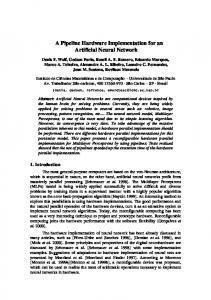
where w j is the weight of the j-th input and T is the threshold value. Representing a threshold function as (1) implies that a threshold element is traditionally implemented by the structure shown in Fig.1. 3
Figure 1. General structure of the neuron threshold model.
It is shown in [6, 7] that any threshold function can be represented in ratio form, as follows: ∑ j∉S w j x j ∑ j∉S w j x j n ; Rt (A/B) = 0 if A < B F = Sign ∑ w j x j − T = Sign − 1 = Rt ∑ wjxj ∑ wjxj 1 if A ≥ B j =1 j ∈ S j ∈ S
(2)
where S is a certain subset of indexes1 such that ∑ j∈S w j = T . From (2) it immediately follows that CMOS implementation of a threshold element can be like that in Fig.2.
β
β
Figure 2. The -driven threshold element ( -DTE).
The voltage Vout at the -comparator output is determined by the ratio of steepnesses ( β n β
and β p ) of n- and p-circuits. Namely by this reason, the threshold element is called -driven ( β
β
DTE). The steepnesses are formed by connecting transistors of respective width in parallel. In [8, 9], to build a threshold element with controllable input weights, a reduced ratio form is introduced: ∑n w j x j n n = Rt ω x ; F = Sign ∑ w j x j − T = Rt j =1 ∑ j j T j =1 j=1 β
that leads to the
ωj = w j / T
(3)
-comparator circuit shown in Fig.3a where β nj = ω j β ; β n = β ∑ j =1 ω j x j ; n
βp = β . 1
To construct S it is sufficient to take any hypercube vertex that lies in the separating hyperplane and to include in S
indexes of the variables having the value 1 on the vertex.
4
β
Figure 3. The -comparator: CMOS implementation (a); equivalent circuit (b).
β
In Fig.3b, a circuit is shown equivalent to that in Fig.3a. The output voltage of the -comparator is determined by the value α = β n / β p in the following way: > Vdd / 2 if α < 1 Vout = . ≤ Vdd / 2 if α ≥ 1
If the output voltage of a CMOS couple (Fig.3b) Vout ≈ Vdd / 2 , this means that both the transistors are in non-saturated mode since both of them meet the condition Vth < Vout < V gs − Vth , V gs = Vdd .2 Hence, 2 Vout I n = β n (Vdd − Vth )Vout − , 2
(V − Vout ) 2 I p = − β p (Vdd − Vth )(Vdd − Vout ) − dd , 2
(4)
I n + I p = 0.
In [6] these equations were analyzed and it was shown that the suggested comparator circuit has sensitivity
dVout ≈ −2 V in the point α = β n / β p = 1. Hence, at the threshold level (Vout = Vdd / 2) dα
the reaction of the -comparator to a unit change of the weighted sum ∆Vout ≈ 2 / T V, i.e. it linearly β
decreases as the threshold grows. β
β
The analysis of -DTE stability to parameter variations made in [5] showed that only -DTE with small thresholds ( ≤ 3, 4) can be stably implemented. However, an artificial neuron is a learnable object and variations of many parameters (for example, technological) can be compensated during learning. β
The learnable LTE on the base of -DTE [8, 9] has a sufficiently simple control over the input β
weight (Fig.4): the control voltage changes the equivalent
2
of the respective synapse. Since the
For simplicity let's assume that the threshold voltage is the same for the both transistors.
5
β
synapse can be in one of two states, conducting or non-conducting, the output voltage Vout of the comparator is formed only by the synapses which are conducting in this given moment.
β
Figure 4. -driven LTE.
Easy to understand that after the threshold is reached, adding new synapses does not change the β
LTE output state. It follows from this that the implementability of -DTE and, hence, of the LTE on its base depends only on the threshold value and does not depend on the number of inputs and sum β
of their weights (this fact was established in [6]). The essential aspect is the sensitivity of the β
comparator to the current change at the threshold point. Since the range of -comparator output voltage is limited within ( 0 − Vdd ), the only way of increasing the -comparator steepness at the β
β
threshold point is increasing non-linearity of the dependency of the -comparator output voltage on the ratio α = β n / β p .
β
2.2 Increasing -comparator Sensitivity β
To increase sensitivity of the -comparator, its transistors should be in the saturated mode when the output voltage is in the threshold zone of output amplifier switching. This can be demonstrated by an example of the equivalent circuit in Fig.3b. Let the gates of both the transistors be fed not by ground and voltage supply but by voltages Vgsp and Vgsn , such that both the transistors are in the saturated mode when Vout = Vdd / 2 . Let us assume for simplicity that Vgsp = Vgsn = Vgs , Vthp = Vthn = Vth , and 0 < Vgs − Vth < Vdd / 2 . Then the equations for the currents flowing through the transistors can be represented as I n = β n (Vgs − Vth ) 2 (1 + λnVout ), I p = − β p (Vgs − Vth ) 2 [1 + λ p (Vdd − Vout )],
(5)
I n + I p = 0.
where the parameters λn and λ p reflect the small increase of the transistor currents that takes place when grows. From these equations we find 6
Vout =
1 − α + λ pVdd
, α = βn / β p
λ p + λn α
(6)
and
λn + λ p + λn λ pVdd dVout =− . ( λ p + λ nα ) 2 dα Let λn = 0.03 1
V
(7)
and λ p = 0.11 1 .3 For Vout = Vdd / 2 , it is easy to calculate from (6) that V
α = 1.15 . Parameter α does not equal to one at this point since the values of λn and λ p are different. When Vdd = 5 V and
dVout = −7.5 V. Thus, the sensitivity of the dα
β
-comparator has
increased by 3.75 times. The less λn and λ p , the more the sensitivity. In the LTE circuit (Fig.4), every synapse consists of two transistors. The gate of one transistor is fed by the input variable x j ; the gate of the other one is fed by the voltage Vcj that controls the variable weight (current in the synapse). β
Let us first consider the lower part of the LTE -comparator where the synapse currents are summed and replace the couples of transistors, which form synapses, by equivalent transistors with characteristics shown in Fig.5. These characteristics were obtained by SPICE simulation.
Figure 5. Characteristics of the transistor that is equivalent to the transistor couple.
To the left of the mode switching line, the transistors are in the non-saturated mode; to the right — in the saturated mode. It is easy to see from these characteristics that when Vout = 2.5 V the equivalent transistors are in the saturated mode, if the control voltage VC < 2.5 V, and in the nonsaturated mode, if VC > 2.5 V. Thus, the saturated mode condition restricts the range of control β
voltage change. Breaking this restriction leads to decreasing the output signal of the -comparator 3
The values of these parameters were taken from the used transistor models.
7
because the currents are re-distributed among the synapses. Indeed, let the smallest weight corresponds to synapse current I min and adding this current to the total current of the other synapses must cause the switching of the LTE. If the synapse with the biggest current is not saturated, decreasing Vout because of the total current increases makes the current of this synapse smaller. The currents of other non-saturated synapses also decrease. As a result, the total current increases by a β
value, which is considerably smaller than I min . This leads to decreasing the output signal of the comparator. The range, in which the control voltages of the synapses change, can be extended with help of extra n-channel transistor M3 incorporated into the circuit as it is shown in Fig.6.
β
Figure 6. The modified -comparator.
The gate of this transistor is fed by voltage Vref 1 such that when the current provides Vout ≈ Vdd / 2 , the transistor is saturated under reaction of the voltage Vgs = Vref 1 − VΣ . Increasing the total current through the synapses by adding a synapse with the smallest current makes VΣ smaller, so that Vgs becomes bigger. The extra transistor opens and the extra increase of the total current compensates the change in VΣ . Thus, due to the negative voltage feedback, the extra transistor stabilizes VΣ and therefore stabilizes the currents through the synapses. In Fig.6, when the control voltage of the synapse has its maximum value ( VC = 5 V), the current through the synapse depends on Vout as it is shown in Fig.7. It looks like a transistor characteristic having two zones: the linear zone and zone of saturation. It is easy to see that when Vout ≈ 2.5 V, the synapse is in the saturated mode. When the voltage Vref 1 gets smaller, the synapse current decreases and a change of the synapse current range narrows down. When Vref 1 increases, the synapse current grows and the linear zone of the characteristic becomes wider that may cause the lost of current 8
stabilization in the working point. Thus, there is an optimum value of Vref 1 . In all experiments Vref 1 = 3 V.
Figure 7. Dependence of the synapse current on Vout when VC = 5 V.
β
Now let us consider the p-channel part o f the modified -comparator (Fig.6). In the working point ( Vout ≈ Vdd / 2 ) it should provide a current corresponding to the maximum value of the threshold of realized functions. For this goal, one p-channel transistor can be used with the reference voltage Vref providing its saturation in the working point. However, in this case the steepness of the characteristic Vout ( I ) in the working point will be insufficient for good stabilization β
of the threshold value of the current. By this reason, the modified -comparator circuit (Fig.6) uses the idea of a cascode amplifier [13, p.287]. It has two p-channel transistors M1 and M2 referenced by voltages Vref 2 and Vref 3 respectively. These reference voltages are selected so that as the comparator current grows, the transistor Ml is saturated first and then M2 becomes saturated. In SPICE experiments Vref 2 = 3.5 V, Vref 3 = 2.5 V. The dependence of voltage VdM 1 on the current at the drain of Ml is shown in Fig.8 (Curve 2).
Figure 8. Curve 1 – dependency Vout ( I ) ; Curve 2 – dependency VdM 1 ( I ) ; Curve 3 – dependency VΣ (I ) .
9
As soon as M 1 comes into the saturation zone, the voltage V gs of M2 begins to change with higher speed because of V gs = Vref 3 − VdM 1 . The voltage drop on M2 sharply grows increasing the steepness of Vout (I ) (Curve 1 in Fig.8). Curve 3 in Fig.8 shows rather good stabilization of the voltage drop VΣ (I ) on the synapses. β
For comparison, Fig.9 contains experimental characteristics of the old and new -comparators adjusted to the function threshold T=89.
Figure 9. Comparator characteristics: curve 1 for the old comparator; curve 2 for the new one.
This experiment shows how the comparator output Vout depends on the number of switched synapses whose control inputs were fed by the voltage min Vc corresponding to the smallest weight of a variable. For the old comparator (Curve 1), the leap of the output voltage in the threshold point is 32mV. The characteristic of the new comparator has a much higher steepness in the threshold zone; the voltage leap in the threshold point is about 1V.
2.3 LTE Circuit and the Way of Teaching
Circuits used for forming control voltages determining weights of input variables of artificial neurons just slightly depend on the way of synapse implementation. Some of these circuits were published (for example, in [14]) and they are of about the same structure. The difference between them is mainly associated with a type of a memory element they use (a capacitor or a transistor with floating gate) and with a way of representing the values of input binary variables ({0,1} or {-1,+1}). In Fig.10, the full LTE circuit is given, which experiments were conducted with. Every its synapse contains 5 transistors and a capacitor. Two of the transistors form one of the parallel branches of β
the -comparator. The input variable arrives at the gate of the lower transistor and the control voltage arrives at the gate of the upper one. This usage of the transistors, as compared to the
10
opposite, makes the synapse current dependable on the control voltage more linearly, reducing to several times the influence of the input variable change on the control voltage.
Figure 10. The LTE circuit.
During teaching, the voltage that controls the synapse current (i.e. variable weight) accumulates on a capacitor. The capacitor charge is allowed to change only when the synapse is active, i.e. when the input variable equals to "1". The capacitor charge increase or decrease is realized by approximately the same quanta that determine a learning step. The learning step is appointed on the base of required accuracy of setting the control voltages. Its value can be controlled by choosing amplitude and duration of "increment" and "decrement" signals. When teaching LTE to fairly complicated threshold functions (with a big value of sum of weights and threshold), the learning step should be small. Usually, algorithms of LTE teaching are built so that as soon as the output signal of the LTE begins to coincide with the value of the learning function, the teaching stops. Due to the small learning step, in cases when the LTE fires after the β
variable with the smallest weight changes its value, the voltage leap at the output of the
-
comparator can exceed the minimum permissible value, which is sufficient for amplifier firing, just by a very small value. To increase the margin of reliability after the teaching, the LTE circuit has three output amplifiers with different (high, middle and low) sensitivity thresholds. The value of the function produced by the taught LTE is taken from the output Fmid . The output signals Fhigh and Flow are β
used only during teaching. After teaching, the voltage leap at the output of the -comparator that causes switching Fmid will be not less than the difference between the threshold voltages of the other two amplifiers.
11
The control voltages, which have been set during teaching, are kept on the capacitors and can change due to parasitic leakage resistances. In this connection, one should organize the procedure of capacity memory refreshment. The three output amplifiers with different thresholds allow solving this problem, for example, by auto-correcting the control voltages using the output signal Fmid as a learning sequence of function’s values. The general structural scheme used when simulating the process of teaching the neuron to a given threshold logical function is shown in Fig.11.
Figure 11. General scheme for experiments.
The generator of input signals periodically produces sequences of value combinations of input variables x1 , x2 ,..., xn and the sequence of values that the given logical function Y takes on these combinations. Teaching/refresh switch passes to its output F either the signal Y (when teaching) or the output signal Fmid (when refreshing). The comparator produces the signals "decrement" and "increment."
Passive values of these signals are equal to "0" and "1" respectively. Their logical
description looks like Decrement = Y ⋅ Fhigh and Increment = Y ∨ Flow when teaching; Decrement = Fmid ⋅ Fhigh and Increment = Fmid ∨ Flow when refreshing. Physically, these signals are realized with limited amplitude and duration, determining the learning step. In experiments with LTE learning, there is an acute problem of selecting threshold functions for teaching what determines simulation time. The duration of experiments is very important because it is often measured in hours and even days. A threshold function for teaching should has - a short sequence of variable combinations checking all possible switches of the function value, - a wide range of variable weights, - a high threshold value for a given number of variables.
12
In more detail, this problem will be investigated in the last section of the paper. It will be shown that a function, which can be represented by the Horner's scheme x n ( x n −1 ∨ xn −2 ( xn −3 ∨ x n −4 (...))) , satisfies to these requirements. For such functions, the sequence of integer values of variable weights and threshold with minimum sum forms the Fibonacci sequence. The length of the checking sequence is n + 1 for the Horner's function of n variables.
2.4 SPICE Simulation Results of LTD Learning
Two series of experiments on LTE teaching to given threshold functions are represented here. The goal of the first series was to show the necessity of using a threshold hysteresis when teaching the LTE and when providing the auto-support of the LTE state after the LTE is taught. The threshold hysteresis can be obtained using three output amplifiers whose characteristics have different thresholds as it is shown in Fig. 12.
Figure 12. Static characteristics of the output amplifiers.
When the movement to the threshold is from the left, the higher value of the threshold is used for learning; when from the right, the LTE learns to the lower value. This leads to stretching out the minimum leap min ∆Vout of the -comparator output voltage in the threshold zone and to automatic β
positioning of the output amplifier threshold with the middle value Fmid into the middle of this leap. Obviously, the hysteresis width should not exceed max min ∆Vout , which is defined by the β
parameters of the p-channel part of the -comparator and by the minimum value Tmin of the logical function threshold: max min ∆Vout = f ( I max min = I comp / Tmin ) where I comp is the comparator current in the threshold zone and I max min is the maximum current of the synapse with the smallest weight. For the teaching, it was chosen the Horner's function of 7 variables: Y7 = x7 ( x6 ∨ x5 ( x 4 ∨ x3 ( x2 ∨ x1 ))) = x7 x6 ∨ x7 x5 x4 ∨ x7 x5 x3 x 2 ∨ x7 x5 x3 x1 , Y7 = x7 ∨ x6 ( x5 ∨ x 4 ( x3 ∨ x2 x1 )) = x7 ∨ x6 x5 ∨ x6 x 4 x3 ∨ x6 x 4 x2 x1 .
(8)
13
From all its possible representations in the form Y7 = Sign( ∑ j =1 w j x j − T ) with integer values of 7
weights and threshold, the representation Y7 = Sign( x1 + x2 + 2 x3 + 3x4 + 5 x5 + 8 x6 + 13x7 − 21)
(9)
is optimum by criterion of min(∑ j =1 w j + T ) = 54 . For this representation, Tmin = 21 . 7
The checking sequence for this function contains 8 combinations. Their order is chosen in such a way that the sequence of the corresponding function values is alternate. The combinations in the checking sequence have one remarkable property: if the LTE is taught to the optimum representation of the function, their change must cause the voltage leaps at the comparator output, which are equal in amplitude. The teaching sequence is a periodically repeated checking sequence. To get illustrative and easily explainable results of the experiment, we had to reduce the β
β
steepness of the -comparator characteristic. In the experiment, the
-comparator parameters were
chosen so that when the threshold was 21, max min ∆Vout was equal to 0.5V. The teaching was conducted with the step equal to 10mV. The results of teaching the LTE to the Horner's function of 7 variables with various hysteresis widths are given in Fig. 13.
β
Figure 13. Output signal of the LTE -comparator learned to the function of 7 variables:
without hysteresis (a), with hysteresis of 340mV (b) and of 450mV (c).
When there was no hysteresis (Fig.13a), the LTE is learned to the function representation with threshold T=267 that strongly differed from the optimum. The voltage leaps at the comparator output vary on the checking sequence from min ∆Vout = 28mV ( 2.732 − 2.704) up to max ∆Vout that exceeds 2V. Obviously, after such teaching, the LTE will have a very bad noise-stability.
14
In the second case (Fig.l3b), the neuron was taught with a 340mV wide hysteresis and learned to the function representation with threshold T=26. The dispersion of the voltage leaps at the comparator output considerable decreased ( min ∆V0ut = 0.37V ; max ∆Vout = 0.9V ) and the noisestability of the LTE significantly increased. In the third case (Fig.13c), the neuron was taught with the hysteresis of 450mV wide. The LTE was learned to a function representation, which was close to the optimum. All the voltage leaps at β
the
output
of
the
-comparator
were
approximately
the
same
( min ∆Vout = 0.48V ;
max ∆Vout = 0.55V ). By simulation it was checked the possibility to provide auto-support of the LTE in the learned state on the base of using threshold hysteresis. With this aim, the leakage resistances of control voltage capacitors were explicitly incorporated to the LTE circuit. The LTE was taught to the Horner's function of 7 variables with 450mV wide hysteresis of output amplifiers threshold. After the teaching, the learning mode was replaced by the refreshment mode. The neuron kept stably functioning on the periodically repeated checking sequence. Signals "Increment" and "Decrement" occurred from time to time correcting the control voltages on the capacitors and supporting them within the permissible limits. The result of correcting the control voltages is easily observable in Fig.14.
Figure 14. Correction of the control voltages in the refreshment mode of LTE operation.
As it is seen from the picture, voltage level Vout = 2.485V corresponding to the value combination 1010110 of input variables was not sufficient to switch the output signal Flow . As a result, the signal "Increment" occurred that increased by 10mV the voltages on the synapse capacitors C7 , C5 , C3 , and C 2 causing the decrease of Vout by 33mV and switching Flow .
On the next combination,
1010100, the level Vout = 2.928V was not sufficient to switch Fhigh . The signal "Decrement" reduced by 10mV the voltages on C7 , C5 , and C3 causing the increase of Vout by 30mV and 15
changing the value of Fhigh . In spite of the correction of the control voltages, the values of the output signal Fmid still corresponded to the values of the function on all combinations of the checking sequence. In the second series of the experiments, the LTE was taught to a threshold function of 10 variables: Y10 = x10 ( x9 ∨ x8 ( x7 ∨ x6 ( x5 ∨ x4 ( x3 ∨ x2 x1 )))) = x10 x9 ∨ x10 x8 x7 ∨ x10 x8 x6 x5 ∨ x10 x8 x6 x4 x3 ∨ x10 x8 x6 x4 x2 x1 ; Y10 = x10 ∨ x9 ( x8 ∨ x7 ( x6 ∨ x5 ( x4 ∨ x3 ( x 2 ∨ x 1 )))) = x10 ∨ x9 x8 ∨ x9 x7 x6 ∨ x9 x7 x5 x 4 ∨ x9 x7 x5 x3 x 2 ∨ x9 x7 x5 x3 x1 .
(10)
This function can be represented in the form Y10 = Sign( x1 + x 2 + 2 x3 + 3x4 + 5 x5 + 8 x6 + 13x7 + 21x8 + 34 x9 + 55 x10 − 89) .
(11)
The checking sequence for the function must contain not less then 11 combinations, which are defined by the terms of Y10 and Y10 in (10). To make the teaching sequence of function values interchanged it is needed to have the odd number of combinations in the checking sequence. For this purpose it is possible to add any combination, on which the function has the value “1”. It is well known that any threshold function is a star. The top vertex of the star is the most convenient candidate to be added to the checking sequence (this improves the learning time). Finally, the checking sequence for the function (10) is x10 x9 x8 x7 x6 x5 x4 x3 x2 x1 Y10 1 1 1 1 1 1 1 1 1 1 1 1
0 1 0 0 0 0 0 0 0 0 0 1
0 0 0 1 1 1 1 1 1 1 1 1
0 0 1 1 0 0 0 0 0 0 0 1
0 0 1 0 0 1 1 1 1 1 1 1
0 0 1 0 1 1 0 0 0 0 0 1
0 0 1 0 1 0 0 1 1 1 1 1
0 0 1 0 1 0 1 1 0 0 0 1
0 0 1 0 1 0 1 0 0 1 1 1
0 0 1 0 1 0 1 0 1 1 0 1
0 1 0 1 0 1 0 1 0 1 0 1
The checking sequence is implemented as it is shown in Fig.15. The last graphic in it represents strobe-signal t that participates in forming “increment” and “decrement” signals. β
In the LTE circuit, the -comparator was adjusted to the maximum sensitivity providing at the threshold T=89 max min ∆Vout ≈ 1V (Fig.9), the hysteresis width was 0.85V, and the learning step was adaptive. The learning step is defined by amplitude and duration of the “increment” and “decrement” signals. These signals provide charging and discharging the capacitors with the current of 0.15uA 16
Figure 15. Single checking sequence of signal value combinations.
and can have the maximum duration equal to the duration of the strobe-signal t (90ns). It gives for the capacitor of 1pF the maximum learning step equal to 13.5mV. The change of the control voltages on the synapse capacitors during the learning is shown in Fig.16. The dynamics of the leaning is easily observable. The control voltages stop changing in the
Figure 16. Changes of the control voltages on the synapse capacitors during the learning.
moment 0.28ms. This means that the learning process is over and it is possible to switch teaching mode to refreshing mode. More accurate the moment of mode switching can be defined with special control signal, which sets the switcher into refreshing mode, if the LTE output Fmid coincides with the output F of the mode switcher on all combinations of some checking sequence. In the refreshing mode, if Fmid and F not coincide on at least one combination of the checking sequence, this control signal sets the switcher into teaching mode. It means that the LTE lost the learned state and must be taught again. The refreshing mode of operation can be interrupted with evaluation process for calculation the value of logical function on some input combination. Obviously, that refreshing and evaluation have to interchange. During evaluation to receive correct results, the LTE output Fmid should be gated. 17
As it is easy seen from Fig.16, stable values of the control voltages approximately correspond to the weights of the variables in the optimum representation of the threshold function (the values are distributed close to Fibonacci numbers). At the time instance equal to 0.28ms, the teaching mode has been replaced by the refreshment mode. Starting from this moment, only rare signals "Increment" and "Decrement" appeared, correcting some control voltages. β
The output signals of the LTE and the output signal of its -comparator in one period of the checking sequence of the refreshment mode is given in Fig. 17. One can see that the smallest leap of
β
Figure 17. Picture of the signals on the outputs of the -comparator
and the LTE in the refresh mode.
Vout at the comparator output is 1V. The output signal Vmid represents the values of the realized function. In cases when the output signals Fhigh and Flow do not correspond to the function value, the control voltages are corrected.
2.5 Implementability Limits of the LTE
In order to study the functional power of the LTE, a number of experiments were carried out with SPICE simulation of its behavior. For all experiments with learnable threshold elements, the problem of choosing testing threshold functions is crucial. This problem will be discussed in the last section of the paper. As it was already noticed, a threshold test-function should match the following demands: — to have the short learning sequence, — to cover a wide range of input weights, — to have the biggest threshold for the given number of variables. Monotonous Boolean functions representable by Horner's scheme match all these demands. For such functions of n variables, the sequence of input weights and threshold forms Fibonacci sequence and the length of the shortest learning (checking) sequence is n + 1 (the number of 18
combinations of input variable values). Experiments were made with three threshold functions for n = 10 , 11 and 12:
F10 = Sign( x1 + x2 + 2 x3 + 3x4 + 5 x5 + 8 x6 + 13x7 + 21x8 + 34 x9 + 55 x10 − 89) , F 11= Sign( x1 + x2 + 2 x3 + 3x 4 + 5x5 + 8 x6 + 13x7 + 21x8 + 34 x9 + 55 x10 + 89 x11 − 144) ,
(12)
F 12= Sign( x1 + x2 + 2 x3 + 3x4 + 5 x5 + 8 x6 + 13x7 + 21x8 + 34 x9 + 55 x10 + 89 x11 + 144 x12 − 233) . Since the learning process was not the object of these experiments, the optimum values of control voltages were set on the synapses. The logical inputs of the LTE were fed by checking (learning) sequences. In the first series of the experiments, max min ∆Vout (the maximum of the smallest change of β
comparator output voltage at the threshold level of 2.7V) was determined. The results of the experiments are given in the second column of Table 1. The implementability of the LTD is determined by the signal ∆Vout value. According to the table, the LTE learnable to functions of 12 variables is quite near the edge of implementability because of relatively small value of ∆Vout . Table 1: Results of SPICE simulations. LTE type
∆Vout
(min÷ max)Vth
δVdd
F10
1V
1.88÷3.7V
0.3%
F11 F12
0.525V 0.325V
1.9÷3.68V 1.97÷3.65V
0.2% 0.1%
In the second series of the experiments, for fixed parameters of the comparator the range of admissible threshold voltages of the output amplifier Fmid has been defined under stipulation that on the range borders the comparator produced min ∆Vout not less then 100mV when the LTE was in the learned state. The results are given in the third column of Table 1. The conclusion is: deviation of the amplifier threshold (e.g. because of technological parameter variations) does not essentially influence upon LTE implementability. The LTE during learning is adjusted to any threshold of the output amplifier from these ranges. The other experiments were associated with the question: with what precision the voltages should be maintained for normal functioning of the LTE after learning. First of all, the LTE stability to supply voltage variations should be investigated. With constant values of the reference voltages, when changing the voltage supply at ±0.1% (±5mV), the dependence of the voltage Vout from the current flowing through p-transistors of the comparator shifts along the axis of current at ±1.5% as shown in Fig. 10. For the LTE F12 , the current in the working point is about 233I min ; 1.5% of this value is 3.51I min , i.e. the shift of the characteristic is 3.5 times more than the minimum current of
19
the synapse. Evidently, the LTE will not function properly when the working current changes like that.
Figure 18. Behavior of the dependency Vout ( I p ) when the voltage Vdd changes in the interval ±0.1%.
On the other hand, taking into account the way of reference voltages producing, it is natural to assume that the reference voltages must change proportionally to the changes of the voltage supply. The effect from reference voltage change is oppositely directed to the effect of supply voltage change and partially compensates it. The experiments carried out under these conditions showed that learned LTE F10 , F11 , and F12 can function properly in respective ranges of supply voltage change shown in the fourth column of Table 1. To fix the borders of the ranges, the following condition was used: signal ∆Vout / 2 should be more or less than the output amplifier threshold by a value not less than 50mV. The control voltages of the synapses were set up with the accuracy of 1mV . With what accuracy should they be maintained after the learning? Evidently, the LTE will not function properly if with the same threshold of the output amplifier the total current of the synapses will drift by I min / 2 in one or the other side. Experiments were conducted to determine the permissible range ± δVC , in which the control voltage VC of one of the synapses (with minimum and maximum currents) can change while the control voltages of the other synapses are constant. The condition for fixing the range borders was the same as in the previous series of experiments. The obtained results are given in Table 2. Table 2: Results of SPICE simulations. Type
δ I S min
δ V C min
δ V C max
F10
± 0.42 I min
± 5.3% ( ±46mV)
± 0.60% ( ±17mV)
F11 F12
± 0.40 I min
± 4.7% ( ±40mV) ± 3.8% ( ±32mV)
± 0.73% ( ±27mV) ± 0.23% ( ±10mV)
± 0.34I min
20
In the second column of the table, the permissible ranges of synapse current change are shown. The third and fourth columns contain the limits of change of the control voltages. These limits define corresponding changes of current in synapses with minimum and maximum weights. It is possible to make the following conclusion basing on Table 2 data: since all the control voltages of synapses in the LTE should be maintained simultaneously, their maintenance as accurate as units of millivolts should.
3 LTE Learnable to Arbitrary Threshold Functions A threshold function with positive input weights is an isotonous Boolean function. Such a function can be realized by an artificial neuron (LTE) with only excitatory inputs. However, most problems solved by artificial neural networks either require inhibitory inputs. If the input type (excitatory or inhibitory) is known beforehand, the problem of inverting the weight sign is solved trivially by inverting the respective variable. Otherwise, the neuron should have synapses capable of forming the weight and type of the input during the learning, using only increment and decrement signals. The possibility of building such synapses for the LTE is the subject of this section.
3.1 Statement of the Problem β
The behavior of a -DTE is described by a threshold function in ratio form [6]. To build the LTE, it is convenient to represent threshold functions in reduced ratio form: n
n
j =1
j =1
F = Rt ( ∑ w j x j / T ) = Rt ( ∑ ω j x j )
(13)
0 if A < 1, where ω j = w j / T and Rt ( A) = 1 if A ≥ 1.
The simplest and obvious way of solving this problem is doubling the number of variables (and synapses) feeding the LTE inputs by both x j and their inversions x j with input weights a j and b j respectively. Note that doubling the number of synapses does not lead to cutting down the number of realizable threshold functions because the implementability of LTE depends only on the threshold value and does not depend on the sum of the input weights or number of synapses. Quite the contrary, incorporating extra inverse inputs increases the number of realizable threshold functions of n variables by 2n times. Let in a certain isotonous threshold function Rt ( ∑ j =1 ω j x j ) some variables xi ∈ Y are n
inverted while other variables x j ∈ Z (i ≠ j, Z U Y = X ) are not. Then
21
F = Sign( ∑ w j x j + x j ∈Z
∑w x i
i
− T ) =Sign( ∑ w j x j +
xi ∈Y
x j ∈Z
∑ w (1 − x ) − T ) = i
i
xi ∈Y
∑x ∈Z ω j x j − ∑x ∈Y ωi xi j i Sign( ∑ w j x j − ∑ wi xi − (T − ∑ wi )) =Rt 1 − ω x j ∈Z xi ∈Y xi ∈Y ∑xi∈Y i
(14)
where ω j = w j / T . It is easy to see from (14) that negative weights use can be reduced to inverting the variables and vice versa. Normalized threshold of a function represented by Rt-formula with negative weights is equal to 1 − ∑x ∈Y ωi . i
The circuit of a neuron synapse capable of forming both positive and negative weights of an input variable is made of two simple synapses as shown in Fig.19.
Figure 19. Synapse forming positive and negative weights of the input variable.
It is easy to see that the LTE with such synapses realizes the threshold function ∑n ( a j − b j ) x j Rt j =1 n 1 − ∑ b j j =1
(15)
where a j and b j are weights brought to the threshold. They are defined by voltages on the capacitors C1 and C 2 for x j and x j respectively. On the other hand, for the case of doubling the synapses number, it follows from (14) that the threshold function realized by the LTE must be n (a j − b j ) x j ∑ j =1 Rt n 1 − ∑ (b j − a j ) Sign(b j − a j ) j =1
(16)
(for keeping the limitations on weights and thresholds). It is easy to see that if in every pair ( a j , b j ) one of the weights is equal to zero, then expressions (15) and (16) coincide and have a view: 22
F = Rt ( ∑ a j x j + x j ∈Z
∑x ∈Z a j x j − ∑x ∈Y bi xi j i . = b x ) Rt ∑ i i 1 − ∑x ∈Y bi xi ∈Y i
(17)
It follows from the above that when teaching a LTE with such synapses it is desirable to change the input weights ( a j , b j ) by such a way that one of the weights in each pare goes to zero. More over, as it will be shown below, this condition provides the maximum level of LTE implementability. It is difficult to conclude from (15) and (16) that synaptic weights affect the neuron β
implementability. Let us look how the -comparator operates (Fig.6). The sizes of p-transistors and β
reference voltages Vref 2 and Vref 3 determine the current I th when the output voltage of the comparator is equal to the output amplifier threshold. As a first approximation, the smallest change of the current is I 0 = I th / T and ∆Vout = kI 0 where k is the steepness of the -comparator voltageβ
current characteristic at the threshold of the output amplifier. However, if a j ≠ 0 and b j ≠ 0 , then via each j-th synapse an additional current flows determined by the value of min(a j , b j ) . Thus, the approximate value of the smallest current can be obtained from the equation I0 =
I th − I 0 ∑ min(a j , b j ) T j
I0 =
I th . T (1 + ∑ j min(a j , b j ))
and (18)
It follows from (18) that if the value of ∆Vout is fixed, the biggest realizable threshold depends on min(a j , b j ) as T≤
kI th . ∆Vout (1 + ∑ j min(a j , b j ))
(19)
Thus, keeping the implementability level requires either increasing I th during the learning (that is actually associated with some difficulties) or providing min(a j , b j ) = 0 for any j by modifying the synapse circuit and changing the learning algorithm. In [20] several modifications of synapse circuits have been suggested and for each of them existence of stable decisions, which the LTE is able to keep to realize non-isotonous threshold functions, has been proved. Unfortunately, authors could not find on-chip learning algorithms leading to these decisions. One of possible solutions is proposed in the next subsection. This solution provides on-chip learning process, which gives convergence independently from initial conditions and uses modified synapse circuit. 23
3.2 The Problem Decision
The same general structure scheme, which is shown in Fig.11, is used when simulating the process of teaching the LTE to an arbitrary given threshold logical function. The “Input Signal Generator” periodically produces checking sequence of value combinations of input variables and the sequence of values that the given logical function takes on these combinations. The isotonous logical function (10) depending on 10 variables is chosen as a test function. The checking sequence for this function represented in Fig.15. Non-isotonous functions can be derived from this function, by inverting some variables with help of inverters. The generator is supposed to be implemented separately from the LTE. Other blocks of the general scheme are assumed on-chip implemented. Bellow schematics for all of them are shown. In the schematics, widths of all transistors are pointed out to make experiments repeatable. The “Teach/Refresh Switch” passes to its output F either the signal Y (when teaching) or the signal Fmid (when refreshing) and realizes the logical function F = Y & Teach ∨ Fmid & Teach . Its schematic is very simple and realized in Fig.20.
Figure 20. Schematic of the switch.
The “Comparator” produces “Decrement” and “Increment”. Its schematic is shown in Fig. 21. In the schematic the “Increment” signal is designated as incr _ p to point out that this signal controls p-channel transistors. Its function together with implementation description is
incr _ p = Flow ∨ F ∨ t = Flow ⋅ F ∨ t where F is the switch output and t is the strobe-signal inversion. This function is realized on the transistors M1 – M6 and M19 – M22. The function logic contains embedded current mirror on the transistors M3 and M4, which restricts the “Increment” current through p-channel transistors
24
controlled by the signal incr _ p . The width of the transistor M3 provides the 0.15uA current through p-channel transistor of the minimum width (1.2u).
Figure 21. Schematic of the “Comparator”.
“Decrement” signals consist of two signals: decr _ n and nincr _ n . The main signal decr _ n has the logical function decr _ n = Fhigh ⋅ F ⋅ t = Fhigh ⋅ F ∨ t that is implemented on transistors M9 – M18. The function implementation contains the embedded current mirror on the transistors (M15, M18), which restricts the signal decr _ n amplitude. The transistor M18 of 117u width provides the “decrement” current 0.15uA through n-channel transistors of minimum width (1.2u) controlled by the signal decr _ n . Additional “Decrement” signal nincr _ n is used to create an additional force that pulls down voltages of the capacitors corresponding to min(ai , b j ) up to the ground potential during LTE learning. It has the logical function nincr _ n = Fmid ⋅ F ⋅ t = Fmid ⋅ F ∨ t
and is implemented on transistors M19 – M30. The last stage of the signal implementation contains the incorporated current mirror on transistors (M28, M30) that restricts to 0.11uA the current in nchannel transistors of minimum width controlled by the signal. β
The LTE itself consists of -comparator with output amplifiers and synapses. The schematic of β
the -comparator is presented in Fig.22. 25
β
Figure 22. Schematic of the -comparator with output amplifiers.
In this picture, all parameters of transistors and values of reference voltages are pointed out. All amplifiers are constructed as a serial connection of three inverters. The amplifier with the output Fmid has the threshold equal to 2.7V. The thresholds of amplifiers with outputs Flow and Fhigh are equal to 2.3V and 3.15V respectively. Thus, the width of threshold hysteresis is 850mV. The full synapse circuit of the LTE learnable to arbitrary threshold functions is introduced in Fig.23. It is constructed on the base of the synapse circuit in Fig.19. Voltages VC1 and VC 2 on the capacitors control the synapse current flowing through pairs of transistors (M5, M23) or (M6, M24). The circuit has to input logical variables x and x . The variable x can be derived with help of an inverter. The voltages VC1 and VC 2 on the capacitors C1 and C2 correspond to the positive a and negative b weights respectively. If VC1 < Vth or VC 2 < Vth (here Vth is the threshold voltage of nchannel transistors), it means that a = 0 or b = 0 because the corresponding transistor pair will be closed. The signals incr _ p and decr _ n increments and decrements the capacitor voltages through pairs of transistors (M1, M3), (M2, M4) and (M7, M25), (M8, M26) respectively depending on the value of input variables (x, x ). Two pseudo nMOS inverters on transistor pairs (M27, M37) and (M28, M38) are sensitive elements of capacitor voltages close to Vth . Voltage Vref 4 = 3.9V fixes the conductivity of their pchannel transistors. Output signals G1 and G2 of these elements control conductivity of two pairs of transistors (M15, M21) and (M16, M22) respectively. Each pair of these transistors opens when the voltage on corresponding capacitor ( VC1 or VC 2 ) exceeds 675mV. Two inverters (transistors M29, 26
M39 and M30, M40) with outputs G3 and G4 invert the signals G1 and G2. These inverters control transistors M9 and M10, each of which open when the voltage of corresponding capacitor ( VC1 or VC 2 ) exceeds 635mV. Signals G3 and G4 write also the information about the sign of the synapse weight in the latch (outputs Q and Q ) on transistors (M31 – M36 and M41, M42). The latch keeps information when voltages of both signals G3 and G4 exceed the threshold of the latch inputs. When Q=Log.1, the weight sign is positive. If Q=Log.0, the sign is negative.
Figure 23. The LTE Synapse implementation.
Signals G1–G4, decr _ n , nincr _ n , and the latch Q, and input variables ( x, x ) control conductivity of additional decrement chains for each capacitor. For the capacitor C1, these chains are described by the expression M 9 (M 11 (M 15 M 25 ∨ M 17 ) ∨ M 13 (M 19 ∨ M 21 )M 25 . For the capacitor C2 the expression for chains is M10 (M 12 (M 16 M 26 ∨ M18 ) ∨ M 14 (M 20 ∨ M 22 )M 26 . The initial setting signal is controls the transistors M43 and M44, which serve only for initial setting the voltages on the capacitors C1 and C2. During learning, the synapse works by the fallowing way. Let us suppose that initially VC1 < Vth and VC 2 > Vth . Then the signals G1 and G2 will be equal to “Log.1” and “Log.0” respectively and the latch Q will be in the state Q=Log.0 (negative weight sign). There are two cases.
27
First, the sign of input variable weight is negative, i.e. it coincides with the state of the latch. In this case the signal nincr _ n together with twice increased by amplitude signal decr _ n pulls the voltage VC 2 to the 0V by the chain (M9, M13, M19, M25) and by the chain (M9, M11, M15, M25) respectively. At the same time the signals incr _ p and decr _ n try to set the voltage VC 2 corresponding to the weight of the input variable x . Second, the sign of the input variable weight is positive, i.e. it does not coincide with the state of the latch. In this case, the learning sequence will provide that for the capacitor C1 increment steps caused by the signals incr _ p will prevail decrement steps caused by the signals decr _ n , nicr _ n and the voltage VC1 will grow. As soon, as VC1 will exceed Vth the sensitive inverter (M27, M37) closes the transistors M15, M21 stopping action of the signal decr _ n by additional chain and the signal nicr _ n . This inverter also switches the inverter (M29, M39), which, in its turn, opens the transistor M10 enabling action of the signals decr _ n by additional chain and the signal nicr _ n . After that, the voltage VC1 will continue to grow up to the weight value and the signals decr _ n , nicr _ n will pull down the voltage VC 2 by tree chains: (M8, M26), (M10, M14, M20, M26), and (M10, M12, M18). As soon, as the voltage VC 2 reaches 675mV, the sensitive inverter (M28, M38) opens the transistors M16, M22 and, when VC 2 = 635mV , switches the inverter (M30, M40), which, in its turn, closes the transistor M9 and switches the letch Q into the state Q=Log.1 (positive weight sign). Output signals of the latch close the transistors (M18, M20) and open the transistors (M17, M19). Difference of critical values of the voltage VC 2 , which lead to switching the sensitive element (M28, M38) and the inverter (M30, M40), is very important because in this case switching of the letch only slightly changes the condition of the capacitor C2 discharging and voltage VC 2 continues to go down up to ground potential.
3.3 Results of SPICE Simulation
All experiments on teaching of the LTE to non-isotonous (antitonous) threshold functions were made for functions obtained by inverting some variables in the isotonous threshold Horner's function (10) of 10 variables. Below results of SPICE simulating LTE learning are presented only for two test-functions: for the isotonous function (10) and for the non-isotonous function (antitonous) derived from (10) by inverting variables with even indexes Y10 = x10 x9 ∨ x10 x8 x7 ∨ x10 x8 x6 x5 ∨ x10 x8 x6 x 4 x3 ∨ x10 x8 x6 x 4 x2 x1 ; Y10 = x10 ∨ x9 x8 ∨ x9 x7 x6 ∨ x9 x7 x5 x4 ∨ x9 x7 x5 x3 x2 ∨ x9 x7 x5 x3 x1 .
(20) 28
Another form of the function (20) representation is Y10 = Sign( − x1 + x2 − 2 x3 + 3x 4 − 5 x5 + 8 x6 − 13x7 + 21x8 − 34 x9 + 55 x10 − 34) .
(21)
The checking sequence for these two functions represented in Fig.15. In experiments, the duration of keeping one combination is 200ns and the checking sequence takes 2.4us. The learning sequence is cyclically repeated checking sequence. Fig.24 shows the LTE learning process to the function (10) starting from the initial state, in which V
С
1
= VC 2 = 0V for all synapses. In this figure, designations ∆V j of curves denote voltage
difference VC1 − VC 2 for the synapse of j-th variable.
Figure 24. The LTE learning to the function (10).
It is easy to see from Fig.24 that all curves reach stable states for the time equal to 0.95ms or for 395 learning cycles and the weights of all variables are positive. As measurements show, the decision is found for 0.75ms (313 cycles). It means that up to this time all min(a j , b j ) < Vth and do β
not act on producing the output signal of the -comparator. At the time instant, equal to 0.95ms, all min(a j , b j ) = 0V .
Fig.25 illustrates the process of LTE learning to the function (20) starting from the same initial state. It is possible to conclude, analyzing Fig.25, that this learning process has the same time parameters as the process in Fig.24. Signs of variable weights and their values are determined correctly: all odd variables have positive weights and all weights of even variables are negative. For the proposed procedure of on-chip LTE learning to arbitrary threshold functions of some number of variables, it is incomprehensible how to prove its convergence analytically. A plenty of SPICE-simulation experiments have been done to be sure that this procedure possess of convergence and doesn’t depend from a type of threshold functions and initial conditions. 29
Figure 25. The LTE learning to the function (20)
In Fig.26 the process of LTE learning to the function (10) is presented for one of the worst cases when from the initial state, in which all synaptic weights are the least negative ( VC1 = 0V , VC 2 = 5V ), the LTE is taught to all positive weights. The picture shows correct result of the learning.
Figure 26. The process of LTE learning to the function (10) from
the initial state of the least negative weights.
Now it is possible to confirm that, if the LTE is taught to realize some threshold function, using its state as initial, it can be repeatedly taught to any other one.
4 Some Functional Problems in Experiments with LTE Learning Developing a hardware implementation (e.g. CMOS) of artificial neurons with critical parameters such as threshold value of realizable functions, number of inputs, values and sum of input weights is a hard technical problem that nevertheless has to be solved [1-8]. While tasks of purely logical design can be solved more or less efficiently in an analytic way, tasks of physical 30
design necessarily require computer simulation (e.g. SPICE simulation). Computer simulation can and must answer the following questions: − What are the limiting parameters of an artificial neuron of certain type? − Are these parameters attainable during the teaching? A modern learnable artificial neuron, which is implemented as a hardware device and oriented to reproducing complicated threshold functions (sum of input weights and threshold >1000), is just a sophisticated analog-digital device, whose maximum functional power is attained, in many cases, by using effects of the second and even the third order in transistor behavior. This, in its turn, requires using models of higher levels (e.g. BSIM3v3.1). Therefore, the dependencies of neuron behavior on the synapse parameters are, generally speaking, non-linear. Because of this, the neuron for simulation should have a wide range of synaptic weights that covers all the range of values, which is studying. This, in its turn, requires that the neuron behavior should be simulated under all necessary combinations of the input signals. It should also be taken into account that simulation results strongly (and sometimes crucially) depend on the parameters of the transistor model in usage. Hence, to get results with a certain level of generality, a number of simulations using different models (e.g. of different manufacturers) should be conducted. Thus, to get an answer to the question about the maximum functional power of the artificial neuron, a serious experimental work is needed, which volume obviously depends linearly on the number of variable value combinations used in every experiment. The existence of a number of neuron circuit parameters, providing reproducing a threshold function of limiting complexity, does not mean yet that the voltages controlling the input weights and threshold for this function can be attained during the teaching. If a control voltage V can change in the interval Vmin ≤ V ≤ Vmax and wmax is the maximum value of corresponding input weight (or threshold), then ∆V = (Vmax − Vmin ) / wmax is the value determining required precision of teaching. Taking into account the possible non-linearity of the dependence w(V ) and necessity to compensate during teaching technological variations of transistor parameters (geometrical sizes, thresholds, etc.), precision of setting the control voltages should be δV = k∆V (k < 1). A teaching system can be considered as a complex non-linear analog-discrete control system with feedback delay. Its analytic study is very difficult, so again one arrives to the necessity of computer simulation as the basic tool of his research. In order to provide required precision, the increment of the voltage controlling the synaptic weight in one-step of teaching (exposing one combination of variable values) should be ≤ δV . Hence, to simulate the process of teaching the artificial neuron to reproduce a threshold function with wmax = 100 ÷ 200 , every combination from the learning sequence should be exposed about 31
1000 times or even more, without respect to selecting the teaching strategy. Because of this, SPICE simulation of the teaching process takes hours. Naturally, duration of the simulation process linearly depends on the length of the learning sequence. Thus, if it is desirable to get reasonable simulation time for highly complicated artificial neurons, for test tasks one should look for threshold functions with learning sequences of the minimum length and with fixed values of wmax . Values of input weights should cover all the value range as tightly as possible. Functions of this type are the subject of the section. Some results of threshold logic that have been known many years ago, at least as scientific folklore, will be used.
4.1 Bearing Sets of Threshold Functions and Checking Sequences
The geometrical model of threshold functions Y = Sign( ∑ j =1 w j x j − η ) is a separating n
hyperplane with the equation ∑ j =1 w j x j − η = 0 . If the combinations of variable values correspond n
to vertexes of a unit hypercube, the threshold function has the value "Log.1" on the vertices that have positive distance to the separating hyperplane (T set) and the value "Log.0" on those, whose distance to the separating hyperplane is negative (F set). Traditionally, the task of synthesizing a threshold element by given sets T and F is reduced to solving a linear programming task: ∑ wj x j −η ≥ 0 x j∈T n . finding min ∑ w j + η at the conditions j =1 ∑ wj x j −η < 0 x j∈F Note that the system of inequalities is redundant since some inequalities majorize some others. Without loss of generality, only threshold functions with w j > 0 will be discussed further. Such threshold functions correspond to isotonous Boolean functions (monotonous functions with only positive variables) and can be realized by neurons with only excitatory inputs. By definition, for monotonous functions f ( X ) , from X j > X i it follows that f ( X j ) ≥ f ( X i ) where X j and X i are certain combinations of variable values. Or, for isotonous threshold functions
∑w x
xk =1∈X j
k
k
−η >
∑w x
xk =1∈X i
k
k
−η .
A monotonous Boolean function in a unit hypercube corresponds to a "star", i.e. a set of subcubes that have at least one common vertex (star vertex) [23]. For an isotonous function, the star vertex is X max = {1,1,...,1} ; for an antitonous function (inversion of the isotonous one) – X min = {0,0,...,0} . The vertex lying on the maximum diagonal of a subcube (at the maximum distance) from the top of the star will be referred to as bearing vertex. The set of bearing vertices for
32
star T will be called bearing set T0 and for star F – bearing set F0 . It is easy to see that vertices X ∈ T0 are the minimum and vertexes X ∈ F0 are the maximum in the respective subcubes. Hence, to solve the linear programming task, it is enough to use only the inequalities corresponding to the bearing sets.4 A subcube of dimension m in an n-dimensional hypercube corresponds to a conjunction of range
n − m in the concise form of a Boolean function.5 This conjunction determines the bearing vertex, namely: for the set T0 , coordinate x j has the value "Log.l", if x j appears in the conjunction and "Log.0" otherwise; for the set F0 , coordinate x j has the value "Log.0", if x j appears in the conjunction
and
"Log.l"
otherwise.
For
example,
for
x1 x3 x6 ⇔ 1010010 ,
n = 7,
x1 x3 x4 x6 ⇔ 0100101 . Thus, the number of vertices in the sets T0 and F0 equals to the number of terms in the minimum Boolean forms of the threshold function and its inversion. It obviously follows from above that, if the artificial neuron is taught to recognize bearing sets, it recognizes corresponding threshold function as well. A learning sequence that consists of input variable value combinations belonging to bearing sets will be referred to as a bearing learning sequence. The length of the bearing learning sequence can vary in a wide range: from n + 1 for the
(
Y = Sign ∑ j =1 x j − n
function
(
n
)
up
to
2C nn / 2 =
)
2 ⋅ n! ( n / 2)! ( n / 2)!
for
the
function
Y = Sign ∑ j =1 x j − n / 2 with odd n. n
4.2 Test Functions
The length of the test sequence as a function of the number of variables means nothing, if it is not correlated with complexity of the threshold function. A natural question arises about estimating threshold function complexity. For simulation tasks, which are discussed here, this complexity is associated with implementability of an artificial neuron. It varies depending on a circuit solution. For a
ν
-CMOS artificial neuron [3-5], its implementability and, hence, threshold function β
complexity estimation is determined by the sum of the input weights. For a -driven artificial neuron [6-8], implementability and complexity are determined only by the threshold value. Keeping in mind these two types of complexity estimation for threshold functions, we will use two criteria of efficiency for test functions, namely: C1 = L(n ) / η and C 2 = L( n ) / ∑ j =1 w j where L(n ) is the n
4
This result has been known in the threshold logics since late 50's or early 60's. As the times are remote, giving any particular references is difficult.
5
For a monotonous function, the concise form coincides with the minimum form.
33
length of the learning sequence in the number of bearing combinations. The less values of these criteria the more efficient the function will be in teaching. Let us start from a simple example considering two threshold functions: n n n Y1 = sign ∑ x j − n ; Y1 = Λ x j ; Y1 = V x j and j =1 j =1 j=n n −1 n −1 n −1 Y2 = Sign ( n − 1) xn + ∑ x j − n ; Y2 = xn ⋅ V x j ; Y2 = x n ∨ Λ x j . j =1 j=1 j =1
Both the functions have the same number of the bearing combinations and L( n ) = n + 1 . Since the threshold is the same for Y1 and Y2 , both functions also have the same value of the first efficiency criteria C1 , C1 (Y1 ) = C1 (Y2 ) = 1 + 1 / n . The only advantage of Y2 is that there is an input with the weight n − 1 . At the same time C2 (Y1 ) = 1 + 1 / n , C 2 (Y2 ) = (1 / 2) + 1 /(n − 1) . Since
C 2 (Y1 ) > C 2 (Y2 ) , Y2 is more preferable as a test function. There arises a question, if it possible to derive test functions with the highest efficiency for the both criteria. Let us consider Boolean functions that can be represented in Horner's scheme:
H 1 ( n ) = xn ∨ x n −1 ( xn −2 ∨ xn −3 ( xn −4 ∨ ...)) , H 2 (n ) = xn ( xn −1 ∨ xn −2 ( xn −3 ∨ x n −4 (...))) , and call them Horner's functions of the first and second type respectively. Note that according to De Morgan's law, inverted functions of the first type are functions of the second type relatively inverted variables, and vice versa, inverted functions of the second type are functions of the first type relatively inverted variables. Let N [T01 (n )] = N [ F02 ( n )] , N [T02 ( n )] = N [ F01 ( n )] be the numbers of vertices in the bearing sets of Horner's functions of n variables of the first and the second type. It is easy to see that
H 1 ( n ) = xn ∨ H 2 ( n − 1)
and
H 2 (n ) = xn H 1 ( n − 1) .
Therefore,
N [T01 (n )] = N [ F01 (n − 1)] + 1 ,
N [ F01 (n )] = N [T01 (n − 1)] and L(n ) = L( n − 1) + 1 = n + 1 . Hence, a Horner's function of n variables has the shortest bearing learning sequence. Statement 1: The first and the second type of Horner's functions of n variables are threshold
functions with the same vectors of input weights W = {wn , wn −1 ,..., w1} differing only in their threshold values. It is easy to find, directly applying De Morgan’s theorem, that Horner's functions of the first and the second type are dual6, i.e. H 1 ( n ) = H 2d ( n ) . 6
Functions
f ( X ) and ϕ ( X ) are called dual, if f ( X ) = ϕ ( X ) .
34
For any threshold function f ( X ) = Sign( ∑ j =1 w j x j − η ) , the following is true: n
n f ( X ) = Sign − ∑ w j x j + η − 1 and j =1 n f d ( X ) = f ( X ) = Sign − ∑ w j (1 − x j ) + η − 1 = j =1 n n Sign ∑ w j x j − ∑ w j − η + 1 j =1 j =1
that proves the statement 1. Statement 2: Input weights of a threshold functions represented by Horner's scheme form the
Fibonacci sequence. It follows directly from the minimum form for Horner's functions that
wn = η1 ( n ) = η 2 ( n − 1) = wn −1 + wn −2 where η1 ( n ) and η 2 ( n ) are thresholds for Horner's functions of n variables of the first and the second type respectively. Solving the difference equation with the initial conditions w1 = w2 = 1 , we get 1 wn = 5
1 + 5 n +1 1 − 5 n +1 − 2 ; 2
η1 (n ) = wn ; η 2 ( n ) = wn +1 ;
n
∑w j =1
j
= wn +1 − 1 .
At the first glance, Horner's functions look like functions of n variables with extreme parameters (sum of input weights, threshold, etc.). However, this is not so, as it is possible to see from simple examples. Already for 4 variables there is a threshold function
x1 x2 x3 ∨ ( x2 ∨ x3 ) x4 = Sign( x1 + 2 x2 + 2 x3 + 3x 4 − 5)
(22)
with the sum of input weights more than that of Horner's functions. From the function dual to (20), by deleting inversions of variables and multiplying it by x5 the next function is derived ( x2 x3 ∨ ( x1 ∨ x 2 ∨ x3 ) x4 ) x5 = Sign( x1 + 2 x2 + 2 x3 + 3x 4 + 5x5 − 9) .
(23)
This function has the threshold more than that of the second type Horner's function of 5 variables. However, both functions (22) and (23) have bearing learning sequences of the length equal to n+3. Note that within practically interesting values of maximum input weights, thresholds, and sums of input weights (100-1000), Horner's functions are an excellent example of test functions. Finally, the following Horner’s functions can be recommended as test functions with the shortest learning sequences: 35
Y8 = Sign( x1 + x 2 + 2 x3 + 3x4 + 5 x5 + 8 x6 + 13x7 + 21x8 − 21) , Y9 = Sign( x1 + x2 + 2 x3 + 3x4 + 5 x5 + 8 x6 + 13x7 + 21x8 + 34 x9 − 34) , Y10 = Sign( x1 + x 2 + 2 x 3 + 3x 4 + 5 x5 + 8 x6 + 13x7 + 21x8 + 34 x9 + 55 x10 − 55) , Y11 = Sign( x1 + x2 + 2 x3 + 3x4 + 5 x5 + 8 x6 + 13x7 + 21x8 + 34 x9 + 55 x10 + 89 x11 − 89) , Y12 = Sign( x1 + x2 + 2 x3 + 3x 4 + 5 x5 + 8 x6 + 13x7 + 21x8 + 34 x9 + 55 x10 + 89 x11 + 144 x12 − 144) , Y13 = Sign( x1 + x 2 + 2 x 3 + 3x 4 + 5x 5 + 8 x 6 + 13x 7 + 21x 8 + 34 x 9 + 55 x10 + 89 x11 + 144 x12 + 233x13 − 233). Table 3 contains bearing sets T0 j and F0 j for functions Y j . In this table, Combinations of variable values {x1 , x 2 ,..., x n } corresponds to decimal equivalents of binary numbers
∑
2 j =1
x j 2 j −1 .
Table 3: Bearing sets for Horner's functions of the first type n
T0
F0
8 85,86,88,96,128
63,79,83,84
9 171,172,176,192,256
127,159,167,169,170
10 341,342,344,352,384,512
255,319,335,339,340
11 683,684,688,704,768,1024
511,639,671,679,681,682
12 1365,1366,1368,1376,1408,1536,2048 1023,1279,1343,1359,1363,1364 13 2731,2732,2736,2752,2816,3072,4096 2047,2559,2687,2719,2727,2729,2730
5 Conclusion The proposed LTE has many attractive features. It is rather simple for hardware implementation β
in CMOS technology. Its -comparator has a very high sensitivity to current changes providing the possibility of getting the smallest voltage leap at the comparator output equal to 1V when the threshold of the realized function is 89 and to 325mV, if the threshold is 233. The implementability does not depend on sum of input weights and is determined only by the function threshold. Such an LTE can perform very complicated functions, for example, logical threshold functions of 12 variables. Carried out experiments confirms this for functions of 10 variables. More over, during LTE learning all dispersions of technological and functional parameters of the LTE circuit are compensated. For enhancement of functional abilities the new circuit of the LTE synapse has been proposed, which gives to LTE opportunity to have both excitatory and inhibitory inputs. The LTE with such synapses can be taught to arbitrary threshold function of some number of variables in the case when it is not known beforehand which inputs are inhibitory and which are excitatory. The on-chip 36
learning procedure, which allows teaching the neuron to arbitrary threshold function of 10 or less variables, has been also proposed. The solution is based on the well-known fact that any Boolean function of n variables can be represented as an isotonous function of 2n variables ( x j and x j ) . The circuit in Fig.23 realizes this idea in the pure form. The function looks like n
n
n
n
j =1
j =1
j =1
j =1
y = Sign( ∑ w j x j + ∑ v j x j − T ) =Rt ( ∑ a j x j + ∑ b j x j ) where, if a j ≠ 0 , then b j = 0 and visa versa. Ability to determine the type of logical variable inputs during the learning increases the number of realizable functions in 2n times as compared with the isotonous LTE implementation (n is a number of variables). We believe that the proposed LTE and its learning procedure can be very useful in many important applications including development of real artificial neurons. Functional power of neurochips depends on not only the number of neurons, which can be placed on one VLSI, but also on functional possibilities of a single neuron. It is evident that extending functional possibilities of a neuron is the prior aim when creating new neurochips. Especially it is very important in the case of a neuron implementation as a digital/analog circuit. The main drawback of the proposed LTE is high requirements to stability of the supply voltage. This drawback looks to be peculiar to all circuits with high resolution, for example, digital-analog and analog-digital converters. It is natural to assume that rather slow changes of the supply voltage (with period not less then tens milliseconds) will be compensated during learning and refreshing. Its fast changes can cause the lost of the learned information. It would be reasonable to study the possibility of compensating the operational parameters LTE by circuit facilities.
References
[1] C. Mead, Analog VLSI and Neural Systems, Addison-Wesley, 1989. [2] S.M. Fakhraie, K.C. Smith, VLSI-Compatible Implementations for Artificial Neural Networks, Kluwer, Boston-Dordrecht-London, 1997. [3]. T. Shibata, T. Ohmi, “Neuron MOS binary-logic integrated circuits: Part 1, Design fundamentals and soft-hardware logic circuit implementation”, IEEE Trans. on Electron
Devices, Vol.40, No.5, 1993, pp. 974 – 979. [4] T. Ohmi, T. Shibata, K. Kotani, “Four-Terminal Device Concept for Intelligence Soft Computing on Silicon Integrated Circuits”, Proc. of IIZUKA'96, 1996, pp. 49 – 59. [5] T. Ohmi T “VLSI reliability through ultra clean processing”. Proc. of the IEEE, Vol.81, No.5, 1993, pp. 716-729
37
[6] V. Varshavsky, “Beta-Driven Threshold Elements”, Proceedings of the 8-th Great Lakes
Symposium on VLSI, IEEE Computer Society, Feb. 19-21, 1998, pp. 52 – 58. [7] V. Varshavsky, “Threshold Element and a Design Method for Elements”, filed to Japan's Patent Office, Jan.30, 1998, JPA H10-54079 (under examination). [8] V. Varshavsky, “Simple CMOS Learnable Threshold Element”, International ICSC/IFAC
Symposium on Neural Computation, Vienna, Austria, Sept.23-25, 1998. [9] V. Varshavsky, “CMOS Artificial Neuron on the Base of Beta-Driven Threshold Elements”,
IEEE International Conference on Systems, Man and Cybernetics, San Diego, CA, October 1114, 1998, pp. 1857 – 1861. [10]
V. Varshavsky,
“Synapse, Threshold Circuit and Neuron Circuit”, filed to Japan's Patent
Office on Aug. 7, 1998, the application number is JPA-H10-224994. [11] V. Varshavsky, “Threshold Element”, filed to Japan's Patent Office on Aug. 12, 1998, the application number is JPA-H10-228398. [12] S. McCulloch, W. Pitts, “A Logical Calculus of the Ideas Imminent in Nervous Activity”,
Bulletin of Mathematical Biophysics, 5, 1943, pp.115 – 133. [13] F.E. Allen, D.R. Holberg, CMOS Analog Circuit Design, Oxford University Press, 1987. [14] A. Montalvo, R. Gyurcsik, J. Paulos, “Toward a General-Purpose Analog VLSI Neural Network with On-Chip Learning” , IEEE Transactions on Neural Networks, Vol.8, No.2, March 1997, pp. 413 – 423. [15] V. Varshavsky, V. Marakhovsky, “Learning Experiments with CMOS Artificial Neuron”, Lecture Notes in Computer Science 1625, ed. by Bernard Reusch, Computational Intelligence
Theory and Applications. Proceedings of the 6th Fuzzy Days International Conference on Computational Intelligence, Dortmund, Germany, May 25-27, Springier, 1999, pp. 706 – 707. [16] V. Varshavsky, V. Marakhovsky, “Beta-CMOS implementation of artificial neuron”, SPIE's
13th Annual International Symposium on Aerospace/Defense Sensing, Simulation, and Controls. Applications and Science of Computational Intelligence II, Orlando, Florida, April 5-8, 1999, pp. 210 – 221. [17] V. Varshavsky, V. Marakhovsky, “Beta-CMOS Artificial Neuron and Implementability Limits”, Lecture Notes in Computer Science 1607, Jose Mira, Juan V. Sanchez-Andves (Eds),
Engineering Applications of Bio-Inspired Artificial Neural Networks. Proceedings of International Work-Conference on Artificial and Natural Neural Networks (IWANN'99), Spain, June 2-4, Springier, Vol. 11, 1999, pp. 117 – 128. [18] V. Varshavsky, V. Marakhovsky, “The Simple Neuron CMOS Implementation Learnable to Logical Threshold Functions”, Proceedings of International Workshop on Soft Computing in
Industry (IWSCI'99), June 16-18, 1999, Muroran, Hokkaido, Japan, IEEE, 1999, pp. 463 – 468. 38
[19] V. Varshavsky, V. Marakhovsky, “Implementability Restrictions of the Beta-CMOS Artificial Neuron”, The Sixth International Conference on Electronics, Circuits and Systems (ICECS'99), Pafos, Cyprus, September 5-8, IEEE, 1999, pp. 401 – 405. [20] V. Varshavsky, V. Marakhovsky, “Non-Isotonous Beta-Driven Artificial Neuron”,
Proceedings of SPIE, Applications and Science of Computational Intelligence III, April 24-27, Orlando, Florida, Volume 4055, 2000, pp. 250 – 257. [21] V. Varshavsky, V. Marakhovsky, “Artificial Neuron Learnable to Threshold Functions”,
WSEAS Transactions on Circuits and Systems, Issue 1, Vol. 3, Jan. 2004, pp. 141 – 148. [22] V. Varshavsky, V. Marakhovsky, H. Saito, “Some Functional Problems in Experiments on teaching Artificial Neurons”, 8-th International Conference on Humans and Computers (HC-
2005), Aizu-Wakamatsu, Japan, August 31 – September 2, 2005, pp. 339 – 344. [23] R.H. Urbano, R.K. Mueller, “A topological method for the determination of the minimal forms of a Boolean function”, IRE Transactions on Electronic Computers, Vol.5, 1956, pp. 126 – 132.
39