Design, Implementation and Testing of An Artificial Neural Network Based Fault. Direction Discriminator for Protecting Transmission Lines. T.S. Sidhu, Member ...
IEEE Transactions on Power Delivery, Vol. 10, No. 2, April 1995
697
Design, Implementation and Testing of An Artificial Neural Network Based Fault Direction Discriminator for Protecting Transmission Lines T.S. Sidhu, Member IEEE
H. Singh, Student Member IEEE
M.S. Sachdev, Fellow IEEE
Power Systems Research Group University of Saskatchewan Saskatoon, Saskatchewan CANADA S7N OW0 Abstract: This paper describes a fault direction discriminator that uses an Artificial Neural Network (ANN) for protecting transmission lines. The discriminator uses various attributes to reach a decision and tends to emulate the conventional pattern classification problem. An equation of the boundary describing the classification is embedded in the Multilayer Feedforward Neural Network (MFNN) by training through the use of an appropriate learning algorithm and suitable training data. The discriminator uses instantaneous values of the line voltages and line currents to make decisions. Results showing the performance of the ANN-based discriminator are presented in the paper and indicate that it is fast, robust and accurate. It is suitable for realizing an ultrafast directional comparison protection of transmission lines.
I. INTRODUCTION The schemes presently used for protecting transmission lines include distance protection, differential protection and directional comparison. Directional comparison relays are set to respond to faults in the protection zone without intentional time delay and are, therefore, used where highspeed fault clearing is needed. With the advent of microprocessors, various analytical methods have been developed and successfully tested to accomplish directional comparison [ 11-[7]. Unfortunately, these approaches do not have the ability to adapt dynamically to the system operating conditions, such as, changing source impedance. Also, these techniques use digital signal processing methods which take time (usually one cycle of the system frequency) to determine the direction of the fault. They are likely to make incorrect decisions if the signals are noisy. It would be desirable to develop a fast, accurate and robust approach that would perform accurately for changing system conditions. Artificial Neural Networks (ANNs) provide a viable alternative because they can handle most situations which 94 SM 433-3 PWRD
A paper recommended and approved by t h e IEEE Power System Relaying Committee of t h e IEEE Power Engineering S o c i e t y f o r p r e s e n t a t i o n a t t h e IEEE/PES 1994 Summer Meeting, San F r a n c i s c o , C A , July 24 - 2 8 , 1994. Manuscript submitted December 30, 1993; made a v a i l a b l e f o r p r i n t i n g May 3 , 1994.
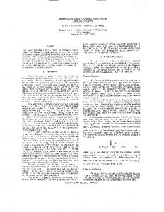
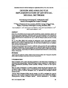
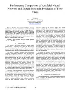
can not be defined sufficiently for finding a deterministic solution. Such an approach will enjoy the advantages which are inherent in ANNs, such as excellent noise immunity, robustness, fault-tolerance, generalization capabilities etc. [8]. As a result, the decisions made by an ANN-based discriminator will not be seriously affected for variations in source impedance and presence of fault resistance. The design and implementation of the ANN-based discriminator are presented in the paper. Training patterns to be absorbed by the ANN were generated using voltage and current samples for faults at various locations along a transmission line. Simulations were performed using an electromagnetic transient program, EMTDC, and a sample three-phase power system. The current and voltage samples were pre-processed using suitable front-end filters. Appropriate transfer functions were used in the various layers of the ANN during training and test runs. The performance of the proposed discriminator was checked using data which was specifically simulated for testing and the fault data recorded from 240 kV and 500 kV transmission lines. Some of the test results are included in the paper. 11. DIRECTION DISCRIMINATION - ANN SOLUTION As is currently understood, the direction of a fault on a transmission line can be determined from the relative phase angles of voltage and current phasors. A polarizing quantity, normally the voltage, is used as reference. The fault current phasor lies within two distinct regions depending on the direction of the fault, the location of the fault, fault resistance, and the source impedance. These two regions, therefore, can be classified as shown as in Fig. 1. The proposed ANN-based direction discriminator does not explicitly use the phase information as the basis of its decisions. It learns from experience gained during the training and recognizes the hidden relationships that might exist in the patterns observed during the learning phase. 111. MULTILAYER FEED-FORWARD NEURAL NETWORK AS A PATTERN CLASSEER Although a single neuron processing unit ( M U ) can handle simplest of the pattern classification problems, MFNNs are needed to handle complicated situations, such
0885-8977/95/$04.00 0 1994 IEEE
698
P
zk = @ [ c w k j y j -
Wok]
f o r k = 1, 2, ........... Q
(2)
j=1
V, la
In this equation, zk is the output of the kth node in the hidden layer, wkj is the weight between the kth node of the hidden layer and thejth node of the input layer and wok is the threshold for the kth node of the hidden layer. The output of the lth node in the output layer is given by
- Polarizing voltage - Pre-fault current - Post-fault current
Q Fig. 1. Directional comparison - A pattern classification problem
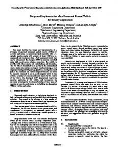
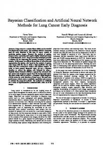
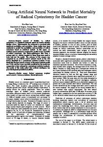
as the patterns which can not be classified using hyperplanes. Theoretically, an infinite number of layers are required to define a decision boundary, but a three-layer F"can generate arbitrary complex decision regions [8]. Fig. 2 shows a three layer, fully inter-connected, feedforward neural network in which each node represents a single NPU as discussed in [9]. The network has N-inputs. Nodes in the input layer function like hyperplanes that effectively partition N-dimensional space into various regions. Each node in the hidden layer represents a cluster of points that belong to the same class. The nodes in the output layer represent the number of classes [lo].
Input Layer (P units)
Hidden Layer Output Layer (Q units) (R units)
Fig. 2. A Three-layer Feedforward Neural Network
The output of the jth node in the input layer can be described as follows:
~[x N
yj =
wjixi - woj1
for j = 1, 2, ........... P (1)
i=1
In this equation, xi is the ith input to the network, y j is the output of jth node of the input layer, wji is the weight between the ith input and jth node of the input layer, woj is the threshold for the jth node in the input layer and @[.I is a non-linear transfer function which can be of various forms, such as hard limiter, sigmoid function or hyperbolic tangent. The output of the kth node in the hidden layer is given by
01 = @ [ C W l k q - wo1]
for 1 = 1, 2, ........... R
(3)
k=l
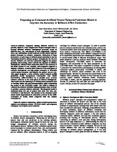
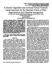
In this equation, o1 is the output of the Ith node in the output layer, wN( is the weight between the Ith node in the output layer and the kth node in the hidden layer and wol is the threshold for the Ith node in the output layer. The weights and the thresholds of the network are determined during training so that the network responds in a specified manner. I v . DESIGNOF THE PROPOSED DISCRIMINATOR This section describes the design of a fault direction discriminator that uses the principles of artificial neural networks. The design process consisted of the following steps: (i) Preparation of suitable training data. (ii) Selection of a suitable ANN structure. (iii) Training of the ANN. (iv) Evaluation of the trained network using test patterns. It is important to appreciate that the design process is iterative. It is possible that a particular ANN structure selected in step (ii) may not train to a designer's satisfaction. In that situation, the structure and parameters must be changed and the network retrained. Also, a trained network from step (iii) may not perform satisfactorily when test patterns are presented to it. Under that condition, the network structure and parameters must be changed, the network retrained and then tested. Important design issues and various aspects of training an ANN as a fault direction discriminator are discussed in the following sections. A. Training Patterns The training patterns should contain the necessary information to generalize the problem. This would enable the network to grasp and absorb the essence of the problem. A. I . Selection and generation A sample three phase power system, shown in Fig. 3, was chosen for the purpose of generating currents and voltages for forward and reverse faults. Z,, and Z,, represent the equivalent source impedances. The details of the sample power system are given in Appendix A. The measurement system, provided on bus-Z, looked for faults towards bus-Y.
699 GI
X
Y
2
G2
Relay
Fig. 3.
A single line diagram of the power system used for
generating training pattems
Training patterns were generated by simulating three phase to ground and single phase to ground faults at various locations in the forward and the reverse directions. Extensive testing revealed that the network was able to generalize the situation from the provided patterns and correctly identify the direction for other types of shunt faults as well. The data for training was obtained by simulating the power system using the EMTDC. The data was analyzed to determine if it contained patterns covering most of the region for forward- or reverse-fault regions shown in Fig. 1. This was accomplished by using a routine which calculated the voltage and current phasors and checked the relevant position of the current phasor. Fault location and fault resistance were changed to obtain the training patterns so that most of the regions were covered. Number of training patterns for both forward and reverse faults were kept equal to avoid "skewed" training. Special care was taken to include boundary patterns. Boundary samples were generated by creating high resistance faults and solid faults near the relay. Training data included a total of 3240 patterns. A.2. Pre-processing and pattern making The process of generating input patterns from the recorded voltages and currents is depicted in Fig. 4. Samples of three phase voltages and currents at the relay location were obtained from the EMTDC. These samples, at 24 kHz, were processed by 4th order low-pass anti-aliasing filters and were resampled at 1.2 kHz. The anti-aliasing filters had a cut-off frequency of 100 Hz. A 3-sample FIR digital filter with unity gain at 60 Hz [ l l ] , then removed the d.c. component. Elimination of the d.c. component enhanced the training capabilities of the discriminator. Voltage and current samples were scaled to have a maximum value of +1 and a minimum value of -1. This was achieved by using a scaling factor equal to the peak value of the normal rated voltage for the voltage samples and 12.5 times of the peak value of normal rated current for the current samples. Patterns were then generated using the processed voltage and current samples.
To MFNN
Fig. 4. Generation of pattems.
B. Training and Adaptation The proposed neural network was trained using the training patterns and the backpropagation algorithm [8]. Three hundred and seventy eight test patterns were generated by creating faults on the same system which was used for generating training patterns. Fault data was preprocessed as discussed earlier. To achieve generalization in the network, training and testing were interleaved. Training was stopped when the mean squared error between the actual outputs and the desired outputs generated for test patterns stopped improving. The learning factor, which controls the rate of convergence and stability, was chosen to be 0.1 in the beginning and was gradually reduced to 0.03. Momentum factor, which is normally added to speed up the training and to avoid the local minima, was kept at 0.9. C. Structure of the Proposed Neural Network The basis and procedures for determining the number of layers, transfer function, type and number of inputs and outputs, and number of neurons for the network are discussed in this section. C. 1. Number of Layers Number of layers in a neural network to be used for solving a pattern recognition problem is governed by the shape of the boundary. As discussed previously, a three-layer FNN can emulate most decision boundaries reasonably well [SI. Three layers were, therefore, chosen for this application. C.2. Choosing Transfer Function A sigmoidal function was used because it helps in producing an arbitrary decision boundary with smooth curves and edges and was found to be implementable on the chosen target system. Non-linear mapping function, @[U], used in this application can be described by the mathematical relationship of (4). @[U] = --2'1 1.05 1+ e-" where: U is the accumulated sum at a neuron.
(4)
This function is continuous and varies monotonically from -1.05 to +1.05 as U varies from -00 to W. The limits of k1.05 were chosen to allow the network to output values of +1 even when U is not large enough for @[.I to saturate. A bipolar sigmoidal function has been used because it provides better resolution and better noise margin.
C.3. Inputs and Outputs Inputs to the network should provide a true representation of the situation under consideration. As the discriminator would indicate the direction of a fault irrespective of the phases involved, it was decided to give an equal representation to each current and voltage. Since digital processing is contemplated, instantaneous values of voltages
700
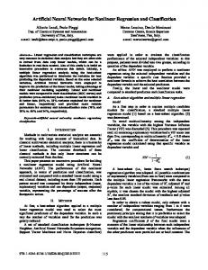
and currents of the three phases were chosen as input signals to the neural network. A sampling rate of 20 samples per cycle (1200 Hz), was used in this application . This sampling rate is compatible with the sampling rates presently used in digital relays [l]. This also means that the total computation time, available for network execution, is limited to 0.833 ms. As output of the network indicates the direction of a fault which is either forward or reverse, one output neuron was used. A forward fault was indicated by an output of +1, while a reverse fault was indicated by - 1. C.4. Number of Inputs and Neurons Number of the inputs to the network and number of neurons in the input and hidden layers were decided by experimentation which involved training and testing different network configurations. The process was terminated when a suitable network with satisfactory performance was established. The performance of the network was checked in terms of its (i) computational requirements (ii) generalization capabilities (iii) response time and (iv) fault tolerance. It is suggested i n [8,12] that starting network should have about one weight for every 5 to 10 training patterns. A number of networks, which had Training Patterns to Weight (TPW) ratio in the range of 5 to 12, were tried. Networks which showed good generalization capabilities, had a response time of 2.4ms and could be executed within one inter-sampling time are summarized in Table I. These networks were further tested to check their performance for data with missing samples and for faults at the relay location. The network finally selected for this application had a TPW ratio of 7.6. It had 12 neurons in the input layer, 4 neurons in the hidden layer and 1 neuron in the output layer. There are 30 inputs to the network; each phase voltage and phase current is represented by its 5 consecutive samples taken at 1200 Hz. The proposed neural network, therefore, is a Time Delay Neural Network (TDNN) and the architecture is same as that of a Finite Impulse Response (FIR) filter. This is illustrated in Fig. 5 which shows inputs from phaseA current. A similar procedure is used for each voltage and current.
D.Network Weights and Biases The weights and biases are used to perform non-linear curve fitting of the data (training patterns) minimizing the error. It was found that the selected weights and biases can not be linked to familiar transformations, such as modal transformation which describes a linear relationship. Also, because of the relationship being non-linear, it is not possible to perform analyses of the network in the same manner as that of a linear system. Further investigations are needed to establish the physical significance of weights and biases.
TABLEI Selection of number of inputs and neurons.
Direction of the fault
A 12-4-1 M F N N
Tapped Delay Line
Fig. 5. A TDNN showing inputs from phase-A current.
V. IMPLEMENTATION The proposed ANN-based fault direction discriminator will form a part of a directional comparison relay whose major functional blocks are shown in Fig. 6. Power system voltages and currents will be acquired by the relay through CTs and PTs. After pre-processing, they will be fed to a fault detector and the proposed direction discriminator. Outputs of fault detector and direction discriminator will then be appropriately ANDed. This whole operation must be accomplished within one sampling interval time, 0.833 ms. Techniques for accomplishing data acquisition and detecting faults are well established and are found not to be computationally intensive [ 11. It was, therefore, decided to concentrate efforts on determining the computational requirements of the ANN-based discriminator. The proposed ANN-based discriminator was implemented on a TMS320C30-based system with BM-compatible microcomputer as a host machine. Implementation software was written in 'C' language and, after compilation and assembly it was down-loaded to the Texas Instruments' TMS320C30-based target board. Floating-point arithmetic was used in the implementation.
Direction
of me Fault
+
Data
1 Power System
Acquisitio ~~~d~ Discriminator
U
Fig. 6. Major Blocks of a Directional Comparison Relay.
70 1
It was found that it took 10317 clock cycles to execute the total network. Given that a clock cycle for a TMS320C30 DSP chip is 60 ns [13], it took only 0.61902 ms to execute the total network; this is well within the available intersampling time of 0.833 ms. This leaves approximately 0.2ms for executing the remaining blocks that are in series with the direction discriminator. VI. TEST RESULTS The proposed neural network was used to determine the direction of faults from the temporal patterns of currents and voltages which were included neither in the training pattern set nor in the test pattern set. The objective of this testing was to evaluate the speed, generalization, prediction and fault-tolerant capabilities of the discriminator. Some results showing the performance of the ANN-based discriminator are presented here.
ANN-based direction discriminator was tested for this capability. Table IV shows the results for 1-@to ground (c-g) faults when the impedance of source 1 is 0.01 and 100 times the impedance of source 2. Fault resistance was 50Q. Performance of the discriminator was also checked for faults at the relay location. Table V shows the performance of the discriminator for faults at the relay location. In digital relaying systems, it is possible to receive bad samples andor miss some samples because of defective data acquisition hardware andor spikeslsurges. Performance of the proposed discriminator was checked when the data
TABLE I11 Estimated Direction for faults involving resistance (b-g fault, fault location 50% of the line length).
A Tests using a Two Machine Power System
The two machine power system, shown in Fig. 3, was used for generating evaluation patterns by simulating faults using an electromagnetic transient program, EMTDC. The threephase voltage and current samples obtained from the simulations were processed as discussed earlier in Section A.2. Labeled patterns were then generated and were presented to the network for evaluation. Tables I1 to VI present the results of this evaluation. Several shunt faults, without any fault resistance, were simulated at different locations on the line and bus sides of the observation point. Power transfer levels on the line were also varied. Table I1 shows the outputs of the proposed discriminator for four cases. Several shunt faults which had different fault resistances were also simulated in both the forward and reverse directions. Table I11 shows the results of this evaluation for two 1 Q to ground (b-g) faults. In power systems, the source impedances can vary significantly, and a practical relay should not be affected by the source impedance variations of the order of 60 times in either directions - increasing or decreasing [6]. The proposed
TABLE IV Estimated Direction for c-g faults with varying source impedances (fault location 50% of the line length, fault resistance 50n).
TABLEI1 Estimated Direction for shunt faults involving no resistance.
TABLE V
702
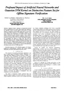
provided to ANN had some samples missing. The faults were created in both forward and reverse directions and involved different phases. Samples having significant values were picked at random and were made zero. Two samples per phase were made zero in an input pattern which consisted of 30 samples. Fig. 7 depicts voltages and currents of phase-A, for a 1-4 to ground (a-g) fault in the forward direction, with missing samples in the data. Table VI shows the outputs of the discriminator when patterns with missing samples were presented.
$
3
1.2
0.6
0.8
0.4
0.4
0.2
5 3g a-0.40
-g
2
0 : -0.2
-0.8
-0.4
-1.2
-0.6 0.09
-7
0.1
0.11
0.12
Time
0.13
0.14
5
0.15
(8)
Fig. 7. Voltage and current of the faulted phase with missing samples.
TABLEVI Estimated Direction using data with missing samples (fault location 50% of the line length).
Test results show that the proposed discriminator is able to determine the direction of the fault three samples after the inception of the fault. The performance is not affected by the direction of the fault, the location of the fault, phases involved, presence of fault resistance, initial power flow conditions and variations in source impedances. The discriminator also performed correctly for faults at the relay location. The indication of the direction for a 3-4) fault is initially correct because a combination of pre-fault and during-fault samples are processed. When sample #5 after the inception of the fault is received, all input voltages become zero but the output remains non-zero because a recursive filter is used for simulating anti-aliasing filter. This anomaly remains for 2-4 samples because the output of the recursive filter depends on the complete previous history of the inputs. To implement the feature of proper discrimination with zero voltage inputs, memory action can be used in the discriminator. Also, correct estimates were obtained when input data had upto two missing samples per
phase in a pattern. The probability of having more than two missing samples per phase per pattern is very small.
B. Tests using Fault Datu Recorded from 240 kV and 500 kV lines In the previous section, it was shown that the proposed discriminator performed correctly on the simulated fault data. The performance of the discriminator was also tested using the fault data recorded from two 240 kV lines of the Alberta Power Ltd. and a 3 19-km, 500 kV transmission line of TransAlta Utilities Corporation. Table VII presents the results of this evaluation. Cases 1 and 1A relate to a 2-4 to ground fault (a-b-g) which occurred on the 240 kV, 84.44 mi long line between Cordel and Anderson substations on June 18, 1993. Case 1 represents the measurements recorded at the Cordel substation while Case I A represents the measurements recorded at the Anderson substation for the same fault. Case 2 relates to a 1-0 to ground (b-g) fault which occurred on another 240 kV, 57.94 mi long line between Cordel and Metiskow substations on June 22, 1993. The measurements were taken at the Cordel substation. Case 3 relates to a 1-4 to ground fault (c-g) which occurred on the 500 kV line at a distance of 151 km from Langdon substation. Case 4 relates to a 2-4 to ground fault (c-a-g) which occurred on the 500 kV line at a distance of 182 km from the Langdon substation. Test results show that the proposed discriminator performed correctly and reliably when field data obtained from the 240 kV lines were used. The voltages of these lines are different from the voltage levels on which the discriminator was originally trained. This became possible because the voltage and current samples were scaled to values between +1 and -1. Estimates for Case 1 and Case lA, from both ends of a transmission line, indicate that the fault is internal. The decision is made three samples after the inception of the fault. The proposed discriminator also performed correctly for faults on the 500 kV line. Also, this data were recorded as 22 sampleskycle compared to the training data which were recorded as 20 sampleskycle. This testing indicates that the proposed discriminator is not affected by variations in the frequency of the power system and the sampling rate. TABLEVI1 Estimated Direction of faults on 240 kV and 500 kV lines.
703
VII. CONCLUSIONS This paper has described an Artificial Neural Networkbased fault direction discriminator for protecting transmission lines. The design process and various design issues have been discussed. The discriminator uses samples of power system voltages and currents to reach a decision. The discriminator was tested extensively by using simulated and field recorded data. Some test results showing the performance of the discriminator are included. Results show that it took only about 2.4 ms to indicate the correct direction of a fault. The determination of direction is not affected by the type of fault, phases involved, power flow conditions, location of the fault, variation in source impedances and the presence of fault resistance. The discriminator also performed correctly for the faults at the relay location and when the data had some samples missing. This shows that generalization and prediction capability of the discriminator make it possible to correctly process the data that only broadly resembles the data it was trained on. Proposed ANN-based direction discriminator was implemented on a TMS320C30-based system and it took only 0.61902 ms to process three phase voltages and three phase currents, and to make a decision. This time is well within the available inter-sampling time of 0.833 ms. This shows that the proposed direction discriminator is within the reach of the present technology and can be used for highspeed directional comparison relaying. REFERENCES M.S. Sachdev, Co-ordinator, Microprocessor Relays and Protection Systems - Tutorial Text, Publication no. 88 EH-0269-1 -PWR, IEEE, New York, 1987. A.G. Phadke, J.S. Thorp, Computer Relaying f o r Power Systems, John Wiley & Sons Inc., New York, 1988. A.T. Johns, M.A. Martin, A. Barker, E.P. Walker, P.A. Crossley, "A New Approach to e.h.v. Direction Comparison Protection using Digital Signal Processing Techniques", IEEE Trans. on Power Delively, vol. PWRD-1, no. 2, Apr. 1986, pp. 24-34. M. Vitins, "A Fundamental Concept for High Speed Relaying", IEEE Trans. on Power Apparatus and Systems, vol. PAS-100, no. 1, Jan. 1981, pp. 163.173. F. Engler, O.E. Lanz, M. Hanggli, G. Bacchini, "Transient Signals and their Processing in an Ultra-high-speed Directional Relay for e.h.v./u.h.v. Transmission Line Protection", IEEE Trans. on Power Apparatus and Systems, vol. PAS-104, no. 6, 1985, pp. 1463-1473. K.S. Prakash, O.P. Malik, G.S. Hope, "Amplitude Comparator based Algorithm for Directional Comparison Protection of Transmission Lines", IEEE Trans. on Power Delivery, vol. 4, no. 4, Oct. 1989, pp.
2032-2041. Y.Q. Xia, J.L. He, K.K. Li, "A Reliable Digital Directional Relay based on Compensated Voltage Comparison for e.h.v. Transmission Lines", IEEE Trans. on Power Delivery, vol. 7, no. 4, 1992, pp. 1955-1962. Richard P. Lippmann, "An Introduction to Computing with Neural Nets", IEEE ASSP magazine, Apr. 1987, pp. 4-22. Don R. Hush and Bill 0. Home, "Progress in Supervised Neural Networks -What is new since Lippmann?", IEEE Signal Processing Magazine, Jan. 1993, pp. 8-39.
[IO]. K.G. Mehrotra, C.K. Mohan, S. Ranka, "Bounds on the Numbers of Samples Needed for Neural Learning", IEEE Trans. on Neural Networks, Vol. 2, No. 6, Nov. 1991, pp. 548-558. [ l l ] . G.B. Gilcrest, G.D. Rockefeller, E.A. Udren, "High-speed Distance Relaying using a Digital Computer", IEEE PES Summer meeting and International Symposium on High Power Testing, Portland, Oregon, July 18-23 1971, Paper no. 71 TP566-PWR, pp. 1235-1243. [12]. D. Hammerstrom, "Working with Neural Networks", IEEE Spectrum, July 1993, pp. 46-53. [ 131. TMS320C30 - User's Guide, Texas' Instruments, Houston, TX.
APPENDIXI. POWER SYSTEM DATA Base Voltage = 500 kV; Base Capacity = 1000 MVA
L
Source data Generator G1
Positive Se . Im . ( .U,) Ne ative S . Im . ( A.)
0.15L90"
Zero Se . Im . ( .U,)
0.034L90"
Generator G2
0.034L90"
l
Transmission Line Data The Mode Surge Impedunces(C2 ): 759.5430 294.5884 294.5884 The Phuse Impedances(Nm ): 0.7435E-04,0.7028E-03 0.5659E-04,0.3261E-03 0.5659E-04,0.3261E-03 0.5659E-04,0.3261E-03 0.7435E-04,0.7028E-03 0.5659E-04,0.3261E-03 0.5659E-04,0.3261E-03 0.5659E-04,0.3261E-03 0.7435E-04,0.7028E-03 The Phase Admittances(mhos/m): 0. ,-.66093E3-09 0. ,-.66093E3-09 0. ,0.36819E-08 0. ,0.368198-08 0. ,-.660938-09 0. ,-,660938-09 0. ,-.66093E-09 0. ,0368198-08 0. ,-.66093E-09 The mode travelling times(m.7): 0.7132312 0.5090359 0.5090359 Tarlochan S. Sidhu received the B.E. (Hons.) degree from the Punjabi University, Patiala, India in 1979 and the M.Sc. and Ph.D. degrees from the University of Saskatchewan, Saskatoon, Canada in 1985 and 1989 respectively. He worked for the Regional Computer Center, Chandigarh, India from 1979 to 1980 and developed software for computer-based systems. He also worked for the Punjab State Electricity Board, India from 1980 to 1983 in distribution system operation and thermal generating station design. After obtaining the Ph.D. degree, he joined Bell-Northem Research Ltd., Ottawa, Canada and worked on a software development project for about one year. He joined, in 1990, the University of Saskatchewan where he is presently Associate Professor of Electrical Engineering. His areas of research interest are power system protection and control and applications of microprocessors and neural networks for power system monitoring, protection and control. Harcharan Singh received the B.E. from the Thapar Institute of Engineering and Technology, Patiala, India in 1986. He worked as Senior Engineer with the National Thermal Power Corporation Ltd., New Delhi. At present, he is working towards the M.Sc. degree at the University of Saskatchewan, Canada. His research interests include applications of neural networks. Mohindar S. Sachdev was bom in Amritsar, India in 1928. He received the B.Sc. degree from Benares Hindu University, India, the MSc. degrees from the Punjab University, India, and the University of Saskatchewan and the Ph.D. degree from the University of Saskatchewan. He worked for the Punjab P.W.D. Electricity Branch and the Punjab State Electricity Board, India, from 1950 to 1968, where he was engaged in system operation, design and planning. In 1968, he joined the University of Saskatchewan, where he is presently Professor of Electrical Engineering. His a r e a of research interest are power system analysis and protection. Dr. Sachdev is a Fellow of the Institution of Engineers (India) and a Fellow of the Institution of Electrical Engineers, London (England). He is a registered Professional Engineer in the Province of Saskatchewan.
704 Discussion V.K. SOOD, (Concordia University,Montreal, Canada) : I congratulate the authors on an excellent publication on the application of neural networks (NNs) for fault identification in transmission systems.
The authors findings are in keeping with our findings [A,B,C] for similar applications. I would appreciate the authors comments on the following :
1. One of the problems of using NNs is the necessity of pre-processing data presented to the selected NN architecture. In the case of input variables of like type (i.e. ac bus voltages), this problem can be resolved by normalization. However, with input variables of different types (i.e. ac bus voltages and line currents), problems may arise since scaling on a common base is not feasible. The authors have tackled this problem by the use of normalizing the voltages, and by dividing the normalized currents by a factor of 12.5. Inherently, this provides a greater weighting to voltage rather than current signals; could the fault identification be successfully implemented with voltage sensing alone? This would imply a lower cost unit. 2. Could the authors provide an explanation why the low-pass antialiasing filters (presumably, for harmonic elimination) and a 3-point FIR filter for dc current elimination (Fig.4) were deemed necessav? Did they do any simulations without these filters? 3. In our findings [A,B,C], we experienced the most difficulty in identifyingline-to-line faults. Did the authors experience similar observations? N.Kandil, YKSood, K.Khorasani and R.VPatel, “Fault Identification in an AC-DC transmission system using Neural Networks”, 1991IEEE PICA Conference, May 6-10, Baltimore. Also published in IEEE Trans on Power Systems, May 1992, Vol7, No 2, pp 812 - 819.
T Grigoriu, YK.Sood, K.Khorasani and R.VPatel, “Fault Identification in a series compensated AC line using Neural Networks.”, Canadian Conference on Electrical and Computer Engineering, Toronto, 13-16 Sept., 1992. T Grigoriu, YK.Sood, K.Khorasani and R.VPatel, “Fault Identification in a series compensated AC line using Neural Networks.’’, Canadian Electrical Association Spring Meeting, Montreal, 29 - 31 March 1993.
The neural net was trained with a set of one and three phase faults. Some test situations present two phase to ground faults (e.g. a-b-g). The authors did not present phase-@phase faults without ground conncetion. Because of the symetric situation patterns should be different h m the training panem set and it would be nice to present a estimated direction of that special fault type (v). Conventional methods use reference voltages to estimate the direction of the fault T h a f o r e , they show at last a very small dead band. The authors presented faults located 1Ooh and 90%. If the fault is closer to the relay, the net might not be able to estimate the direction anymore because the voltage signal is close to zero. Has the proposed neural network approach a dead band (vi) ? The last point is how works the approach if a load jump is presented to the neural net and the fault detection signals an unnormal situation (vii). A pzper on the same topic has been presented at NAPS 1993 [A] and Siemens AG has already applied for a patent @3] in 1993. References: [A] Dalstein, T.; Sobajic, D.; Kulicke, B.; Pao, Y.H.: Neural Network Approach to Fault Direction Identification in Electric Power Systems. IEEE North American Power S!mposium, October 11-12, 1993, Washington D.C., USA. [B] Neural Network Approach to Direction Identification in Electric Power Systems. Patent application GR 93 E 8553 DE. Applier: Siemens AG, Inventor T. Dalstein.
Manuscript received August 26, 1994.
M. KEZUNOVIC, Texas A&M University, College Station, Texas 77843-3128. The authors are to be congratulated for their innovative approach to the use of neural networks in d e signing a fadt direction discriminator. The well organized and clear presentation of the subject matter is indeed particularly valuable since this is a new concept which mey not be familiar to many professionals in the field. Being involved in a similar work,the following are the areas of particular intercat: Why the proposed neural network utilized in this study was chosen over some other types available in the literature? Are there some computational, selectivity or dependability advantagea?
Manuscript received August 15, 1994.
B. Kulicke: The authors have presented an interesting approach to fault direction discrimination for protecting single transmission lines. The method is based on neural network and digital processing technologies. One of the intresting points are DC compensation with an FIR-filter. On the other hand filtering needs time and the neural net should also be able to learn direction estimation even in the presents of DC-components. In that case, training set must include patterns derivated from different fault start situations. The authors have examined direction relay performance for a single line. Real world applications often consist of parallel transmission lines or more. Direction discrimination on such lines is more difficult. Would that approach work on a parrallel line (i) ? Our next point is that the approach demands the fault detection because the net was only trained with fault pattems. Therefore, we think the neural net can not handle faultless situations and depends on an accurate fault detection. The fault detection has to .be very fast to supporl the proposed ANN-based discriminator. What about the discriminator if the fault detection detects a high impedance single phase fault a half cycle delayed (ii) ? In that case,no sample input indicates a faultless situation anymore. The proposed net does not get reference signals as inputs. Hence, actually the net has not learned a relation to the faultless situation. The authors presented each time 7 samples. For reasons, direction of a near located arcing faults can switch the direction. Because the net does not use reference signals it should not be able to estimate a dynamic direction in a reliable manner. Did the authors test the approach with switching directions (iii) ? How responses the net if a forward and reverse fault occur at the same time (iv) ?
How did the authors come up with a number of 3240 patterns being a choice for the training set? What was the criteria for selection of the test cases for the training set?
Could the authors provide some summary results of their tests which will give statistic d basis to judge the overall selectivity and dependability? A classification of these results according to fault types and system conditions would be quite useful. T.S. Sidhu, H. Singh and M.S. Sachdev, Power Systems Research Group, University of Saskatchewan, Canada. We thank the discussers for their interest in the paper. Our response to their questions and comments is as follows:
705
M. Kezunovic 1.Artificial neural networks described in the literature can be classified as Multilayer FeedForward Networks (MFFNs) and recurrent networks. In MFFNs, all information flows in the forward direction and there is no feedback. In recurrent networks, output not only depends on the present inputs but also on the past outputs. MFFNs have been successfully used as pattern classifiers whereas recurrent networks have been mainly used for optimization problems. MFFNs were used because fault direction discrimination was formulated as a pattern classification problem. In addition, MFFNs have lower computational burden. They also have fast transient response in comparison to recurrent networks. 2. The training patterns were selected to cover the forward- and reverse-fault regions shown in Fig. 1 of the paper. A total of 120 single-phase to ground and threephase to ground faults at different locations, and with different fault resistances, were simulated. From each fault, 27 labeled patterns were generated. The training data, therefore, included a total of 3240 patterns. 3. The performance of the trained network was evaluated using data from (I) a two machine system of Fig. 3 of the paper, (ii) a six bus model of the SaskPower transmission network, and (iii) fault recordings from 240 kV and 500 kV lines. Evaluation patterns from the two machine system included all types of shunt faults applied at different locations along the line which also included the relay location. Fault resistance was varied from 0 to 75 ohms and ratio of the source impedances at both ends was varied from 0.01 to 100. Initial power flow conditions were also varied and faults in the forward and reverse directions were simulated. For the six bus power system, all types of shunt faults on two lines were simulated. Fault resistance was also varied. The fault data recordings from the 240 kV and 500 kV lines represented eight faults of the single-phase to ground and two-phase to ground types. These faults occurred at different times on different lines and, therefore, represented different system conditions. The response of the proposed discriminator to all these patterns was found to be correct. V.K. Sood 1. The necessity for different scaling for voltages and currents arises from the fact that the inputs to the network should be between +1 and -1. However, if the scaling of the inputs during on-line application of the network is done in the same manner as was done during training, the performance of the network should not be affected. In our opinion, the fault direction discrimination can not be achieved with voltage signals only. As shown in Fig. 1 of the paper, fault current phasors occupy distinct regions with reference to the voltage phasors during forward- and reversefaults. Therefore, both voltages and currents are required for applying the proposed approach. 2. Low-pass filters are required to avoid aliasing and 3point FIR filter eliminates the dc component from the
signals. It was found that elimination of the dc component reduces the training time significantly and improves the training ability of the network. 3. We did not encounter any difficulty in discriminating line-to-line faults. (Please refer to item 5 of our response to Mr. Kulicke’s discussion).
B. Kulicke 1. We do not see any problem in applying the proposed method of fault direction discrimination to parallel transmission lines. 2. Mr. Kulicke’s contention that for proper working of the proposed discriminator fault detection must be very fast is not correct. If for some reason, a fault is not detected quickly, the decision of the protection system would be delayed but the discriminator will make a correct belated decision. On the other hand, relay literature [1,2] suggests that fault detection can be accomplished within a couple of samples after the inception of the fault. 3. The discusser seems to have misunderstood the working of the proposed ANN-based discriminator. The network is presented with 30 samples (not with 7 samples) at one time 5 samples each representing three voltages and three currents. Also, the proposed ANN keeps giving the correct output beyond sample #7 which are not shown in Tables I1 to VI1 because of space limitations. As mentioned in the paper, the use of memory action is needed when all three voltages are zero for a three-phase fault at the relay location. However, for single- and twophase faults, the reference is drawn from the voltage(s) of the unfaulted phase(s). Some test results for faults at the relay location are shown in Table V of the paper. 4. The network was not trained to detect simultaneous forward- and reverse-faults and, therefore, was not tested for these situations. 5 . Table D.1 shows the output of the proposed discriminator for phase-to-phase faults on the two machine system shown in Fig. 3 of the paper. Results indicate that the proposed discriminator performs correctly. TABLED. I Estimated Direction for faults involving resistance (b-c fault, fault location 50% of the line length).
6. The proposed discriminator does not exhibit any dead band. Performance of the discriminator for faults at the relay location is shown in Table V of the paper. Table D.2 shows output of the proposed discriminator when faults
706
occur at 20% and 100% of the line length in a two machine system shown in Fig. 3 of the paper. The output of the network indicates that the fault direction is determined correctly.
TABLE D.2 Estimated Direction for shunt faults involving no resistance.
7. A fault detection scheme can be designed to distinguish between a load jump and a fault. It can be accomplished because a load jump exhibits different characteristics than a fault. Investigation into the use of artificial neural networks for fault direction discrimination was started by us at the University of Saskatchewan in 1992 and preliminary results were published in 1993 [Dl]. REFERENCE [Dl] Sidhu, T.S., Singh, H. and Sachdev, M.S., “An Artificial Neural Network Based Directional Discriminator for Protecting Transmission Lines”, Proceedings of the 1993 Canadian Conf. on Electrical and Computer Engineering, Vancouver, B.C., Sept. 14-17, 1993, pp. 205-208. Manuscript received October 26, 1994