visible light communication (VLC) systems, in this paper, motivated ..... [11] S. Haykin, âCognitive radio: brain-empowered wireless communication,â. IEEE J. Sel.
> REPLACE THIS LINE WITH YOUR PAPER IDENTIFICATION NUMBER (DOUBLE-CLICK HERE TO EDIT)
REPLACE THIS LINE WITH YOUR PAPER IDENTIFICATION NUMBER (DOUBLE-CLICK HERE TO EDIT)
REPLACE THIS LINE WITH YOUR PAPER IDENTIFICATION NUMBER (DOUBLE-CLICK HERE TO EDIT) < where Pl is the transmit electrical power allocated to the l-th PU, D1 Amin A and D2 Amax A with A being the DC bias which is added to satisfy the non-negativity of the transmitted signal, and Amin and Amax being the minimum and the maximum optical powers in the linear region. s k and s l are the massages for the k-th SU and the l-th PU, respectively. B. Problem Formulation Different from the conventional RF communication systems, the unique optical constraints in (4) for power allocation should be considered in VLC systems. In the multi-cell C-VLC system, the goal of our proposed flexible resource allocation approach is to maximize the sum rate of SUs, and the optimization problem is expressed as k ,z , k ,m , k ,n Pz ,m , Pk ,m , Pk ,n
s.t.
k 1 z1 k ,zCk ,z m1 k ,m Ck ,m n1 k ,n Ck ,n (5a) 2K
maximize
Z
M
N
k 1Pk Pmax ; k K 1Pk Pmax K
D1
2K
K k 1
Pk sk
L l 1
(5b)
Pl sl D2 ; D1
2K k K 1
Pk sk
2L l L1
Pl sl D2 (5c)
Pk ,z 0, k , z; Pk ,m 0, k , m; Pk ,n 0, k , n
(5d)
k 1 n1 k ,n Pk ,nhk2,l ,n I lth , l
(5e)
2K
N
C k C ktar , k
Z Z; z 1 k , z
(5f)
M m1 k ,m
M;
N n1 k ,n
N
3
requirement has the priority to be allocated with the optimal subchannel with high CNR so as to meet its QoS requirement firstly. After satisfying QoS requirements of all SUs, we allocate the excess subchannels to maximize the SUs’ sum rate. B. Power Allocation Approach Here, for the given subchannel allocation, the problem (5) is expressed as maximize
Pz ,m , Pk ,m , Pk ,n
k1 z1 k ,zCk ,z m1 k ,m Ck ,m n1 k ,n Ck ,n 2K
s.t. k 1Pk Pmax ; K
Z
M
N
k K 1Pk Pmax 2K
(6a) (6b)
D1 k 1 Pk sk l 1 Pl sl D2 ; D1 k K 1 Pk sk l L1 Pl sl D2 (6c) K
L
2K
2L
k 1 n1 k ,n Pk ,nhk2,l ,n I lth , l
(6d)
C k C ktar , k
(6e)
2K
N
Clearly, the problem in (6) is nonconvex as (6a), (6c) and (6e) are nonconvex. However, we can apply the Sequential Quadratic Programming (SQP) method [16] combined with the scatter search to achieve the electrical transmit electrical power solution P , which is a powerful iterative algorithm for solving the non-linearly constrained optimization problems [16]. In addition, the interior point method is also used in the SQP programming, and the solution details can be seen in [17].
(5g)
where hk ,l , n is the channel gain from the k-th SU’ associated LED to the l-th PU on the subchannel n. Constraint (5b) is that the total transmit power allocated to all SUs per cell across all selected subchannels should not exceed the maximum transmit electrical power Pmax for SUs per cell. (5c) is the constraint due to the limited liner optical power range, the peak optical intensity and the non-negativity of the transmitted signal [5], [7]. (5d) is the non-negative power constraint across all subchannels. (5e) is that the generated interference to PUs must below a specified interference threshold I lth . (5f) is to ensure that the sum rate of the k-th SU must satisfy the minimum rate ( Cktar ) requirement of each k-th SU. (5g) is imposed to guarantee that the sum of assembled subchannels should not exceed the number of the available subchannels. III. OPTIMAL SUBCHANNEL AND POWER ALLOCATION As we can see, the optimization problem in (5) is a mixed programing problem since both the subchannel assignment and power allocation are involved, which is hard to solve in general. Here, we divide it into two separate subproblems: a subchannel allocation problem and a power allocation problem, and solve these two subproblems separately, and then apply an iteration scheme to converge to an optimal point [12]. A. Subchannel Allocation Approach In this subsection, we show how to achieve the optimal subchannel allocation for the given power allocation. We first define the channel-to-noise ratio (CNR) in the regular mode as Gkrg, z hk2, z / 2 , in the overlay mode as G kov, m hk2, m / 2 , and in the underlay mode as G kun, n hk2, n /( Pl , n hl2, k , n 2 ) . The key principle of the proposed subchannel allocation approach is that the SU whose rate is farthest away from its target minimum rate
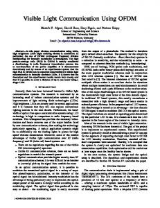
IV. NUMERICAL RESULTS In this section, we evaluate the performance of the multi-cell C-VLC system with the proposed hybrid overlay/underlay resource allocation (denoted as C-VLC hybrid) and compare it with the following systems: 1. conventional non-cognitive VLC system (denoted as Non-C-VLC); 2. C-VLC system with only overlay mode (denoted as C-VLC overlay); 3. C-VLC system with only underlay mode (denoted as C-VLC underlay). We consider an indoor two-cell C-VLC system with two LEDs, where the spacing between two LEDs is 3 m and the vertical distance between the LEDs and the users is 2.15 m. The served coverage on the receiving plane of one cell is a circular area with a radius of 3 m. We choose the 4-quadrature amplitude modulation (4-QAM) scheme in the system. We only consider the LOS components [4], and the DC bias A 20 dBm , Amin 0 and Amax 30 dBm [5]. There are L=2 PUs, N=20 underlay subchannels, M=5 overlay subchannels and Z=5 regular subchannels allocated to SUs. The power allocated to PUs per cell is 15 mW. The modulation bandwidth B is set to 20 MHz and the noise PSD is N0=10-21 A2/Hz. We repeat the simulation 1000 times with random locations of users in each time and present the average sum rate of PUs and SUs. Fig. 3(a) shows the average sum rate of PUs and SUs per cell versus the maximum transmit electrical power Pmax for SUs per cell when Ith=10-11 mW and K=3. We can observe that all the three C-VLC systems achieve much higher sum rates of SUs than that of the Non-C-VLC system, while the sum rates of PUs in the C-VLC hybrid and C-VLC underlay systems are slighted reduced. The C-VLC system allows SUs to access the subchannels of PUs by applying the overlay or underlay modes, which can enhance the spectral efficiency. However, the SUs’ associated LED generates interference to PUs in the underlay
> REPLACE THIS LINE WITH YOUR PAPER IDENTIFICATION NUMBER (DOUBLE-CLICK HERE TO EDIT)