This article has been accepted for publication in a future issue of this journal, but has not been fully edited. Content may change prior to final publication. Citation information: DOI 10.1109/TCOMM.2017.2691710, IEEE Transactions on Communications
1
Multi-User Visible Light Communication Broadcast Channels with Zero-Forcing Precoding Thanh V. Pham, Student Member, IEEE, Hoa Le-Minh, Member, IEEE, and Anh T. Pham, Senior Member, IEEE
Abstract—This paper studies zero-forcing (ZF) precoding designs for multi-user multiple-input single-output (MU-MISO) visible light communication (VLC) broadcast channels. In such broadcast systems, the main challenging issue arises from the presence of multi-user interference (MUI) among noncoordinated users. In order to completely suppress the MUI, zero-forcing (ZF) precoding, which is originally designed for radio frequency (RF) communications, is adopted. Different from RF counterpart, VLC signal is inherently non-negative and has a limited linear range, which leads to an amplitude constraint on the input data signal. Unlike the average power constraint, obtaining the exact capacity for an amplitude-constrained channel is more cumbersome. In this paper, we first investigate lower and upper bounds on the capacity of an amplitudeconstrained Gaussian channel, which are especially tight in the high signal-to-noise (SNR) regime. Based on the derived bounds, optimal beamformer designs for the max-min fairness sum-rate and the maximum sum-rate problems are formulated as convex optimization problems, which then can be efficiently solved by using standard optimization packages. Index Terms—VLC, multi-user MISO, precoding, max-min fairness, sum-rate maximization.
I. I NTRODUCTION The ever-increasing demand for high data-rate wireless communications has spurred a rapid progress in the research and development of visible light communication (VLC) technology. Exploiting the massive deployment of light emitting diodes (LEDs), VLC is expected to serve as a possible complement to the existing wireless technologies in the future indoor networking. This is mainly due to a number of advantages brought by VLC: dual functionalities (illumination and communications), license-free spectrum, high signal-tonoise ratio (SNR) and high security to name a few [1]–[4]. To open the road for commercialization, VLC has also been standardized for wireless personal area networks (WPANs) in IEEE 802.15.7 [5]. Despite the promising benefits, practical deployment of VLC systems faces numerous challenges in which achieving high data rate is one of the major concerns due to the limited modulation bandwidth of the LED. Extensive research effort has been devoted to the data rate improvement of VLC systems [6]–[9]. Among proposed methods, multipleinput multiple-output (MIMO) is one of potential solutions This work was presented in part at the IEEE Global Communications Conference (GLOBECOM), Workshop on Optical Wireless Communications (GC 2015 WS-OWC), San Diego, CA, USA, Dec. 2015. Thanh V. Pham and Anh T. Pham are with the Department of Computer and Information Systems, The University of Aizu, Aizuwakamatsu 965-8580, Japan (e-mail:
[email protected];
[email protected]). Hoa Le-Minh is with the Faculty of Engineering and Environment, Northumbria University, Newcastle upon Tyne, United Kingdom (e-mail:
[email protected]).
by exploiting the spatial multiplexing gain. Some experiments have demonstrated that high data rates up to gigabits/s can be achieved with the combination of MIMO and orthogonal frequency division multiplexing (OFDM) technologies. The use of multiple separated LED sources to form the MIMO transmission is also natural since it helps to guarantee the illumination standard (typically > 300 lux) for lighting a large room/office. A number of studies on MIMO-VLC systems, including both theoretical analysis and experimental demonstrations, have been recently reported [9]–[15]. In these studies, VLC systems with one receiver (unicast transmission) were examined. VLC networks can be nevertheless categorized as broadcast networks, which are able to serve multiple users simultaneously, due to the broadcast nature of visible light signal. This is regarded as multi-user (MU) MIMO-VLC broadcast systems which are analogous to the RF ones; and the presence of multiple users, which results in the so-called MU interference (MUI), consequently degrades the performance. It is generally difficult to handle the MUI at receivers when there is no coordination among them. As a result, MUI effect mitigation should be done at the transmitter side. This is the idea behind precoding techniques applied in MU broadcast channel by pre-processing the transmit signal before transmission. Precoding techniques for RF broadcast channels have been extensively investigated [16]–[19]. Nevertheless, adoption of those techniques for VLC is not straightforward because the RF signal is complex-valued, which is fundamentally different from the real and non-negative VLC signal. Several studies on precoding design for MU-VLC systems, which mainly focus on linear precoding algorithms with either mean square error (MSE) or zero-forcing (ZF) criterion, have been reported. In particular, for the case of multiple photodiodes (PDs) at the receivers, i.e. MU-MIMO configuration, [20]–[22] studied the use of block diagonalization (BD) precoding [17] which can be regarded as a generalization of the ZF precoding. It is noted that our study in [22] is the first work that took into account the non-negativity signal constraint in designing the BD precoding for MU-MIMO VLC systems. In case of single-PD receivers, or the MU-MISO configuration, precoding matrices based on the MSE criterion were designed to minimize the sum MSE [23] or to minimize the maximum MSE among users, i.e., max-min fairness MSE, [24]. Following these studies, the sum-rate performance of MU-MISO VLC systems with ZF precoding, one of the most critical performance metrics in multiuser systems, is reported [25], [26]. There are nevertheless two important limitations in these studies. Firstly, these studies in fact did not consider the sum-rate in terms of channel capacity, which is defined
0090-6778 (c) 2016 IEEE. Personal use is permitted, but republication/redistribution requires IEEE permission. See http://www.ieee.org/publications_standards/publications/rights/index.html for more information.
This article has been accepted for publication in a future issue of this journal, but has not been fully edited. Content may change prior to final publication. Citation information: DOI 10.1109/TCOMM.2017.2691710, IEEE Transactions on Communications
2
as the maximum mutual information between the input and the output for which an arbitrarily small bit error-rate (BER) can be achieved. On the contrary, the sum-rate optimization problem is formulated by adopting the expression in [29, Eq. (24)], which particularly specifies the achievable data rate for an optical intensity modulation/direct detection (IM/DD) channel with multi-level M -ary pulse amplitude modulation (PAM) given a minimum BER threshold. By doing so, the problems could be formed as convex optimization ones (which then can be solved by standard optimization packages) because the achievable data rate expression depends on the ratio of the amplitude signal to the standard deviation of noise, i.e., root square of the SNR in [25], [26]. Secondly, it is well-known that ZF precoding design has a close relationship with the concept of generalized inverse in linear algebra as its function is to invert the MU channel. In previous studies, the ZF precoding was chosen in the form of pseudo-inverse, a special generalized inverse of the channel matrix, which has been proved to achieve the optimal precoding design in MU-RF systems with average power constraint [16]. In VLC systems nevertheless, the combination of peak power due to the limited linear range (further elaboration in the next Section) and non-negativity signal results in the amplitude constraint. The pseudo-inverse therefore may not necessarily result in the optimal solution. This paper attempts to tackle both limitations. First, we examine the sum-rate performance of MU-MISO VLC systems in terms of the channel capacity with the amplitude constraint. It is necessary to note that the study on lower bound on the VLC channel capacity of MU-MISO VLC systems with the amplitude constraint was reported in [27], [28]. In this paper, we extend these studies by the derivation of an upper bound and other two lower bounds with different degrees of tightness. Asymptotic behaviors of these bounds will be also discussed to confirm their validity in characterizing the sum-rate performance. Secondly, we solve the sum-rate optimization problems according to the considered bounds, and prove that the pseudo-inverse is not necessarily the optimal solution under the amplitude constraint. Finally, two iterative algorithms are proposed to find the generalized inverse solutions for the optimal precoding designs in the case of sum-rate maximization. Convergence behaviors of the proposed algorithms will also be evaluated to validate their efficiency. It is important to highlight that the capacity-achieving distribution for the amplitude-constrained Gaussian scalar channel is discrete with a finite number of mass points, and from this observation, a numerical algorithm was developed to determine the capacity and the optimal input distribution [30]. In addition to the exact solution, several closed-form lower and upper bounds were also derived in [31], [32], [35]. Furthermore, in the case of broadcast systems with precoding, both precoding matrices and the input distribution should be, in principle, jointly optimized to compute the channel capacity. To the best of our knowledge, there has been no study on this problem. In this paper, instead of finding an exact solution, we investigate a suboptimal approach by omitting the optimal input distribution condition. In particular, we rely
on previously proposed capacity bounds for scalar Gaussian channels and focus on the optimal ZF precoding design. The remainder of the paper is organized as follows. In Section II, we revisit the issue of scalar Gaussian channel capacity with an amplitude signal constraint. Simple lower and upper bounds of the capacity are provided as benchmarks for the precoding designs in the MU scenario. Section III introduces the model of MU-MISO VLC broadcast systems, linear precoding scheme and the discussion on amplitude constraint on LEDs. A brief review of ZF precoding is provided in Section IV. In Section V, we present the optimal precoding matrix designs with respect to lower and upper capacity bounds for the max-min fairness and the maximum sum-rate criterions, respectively. Numerical results and discussions are given in Section VI, and finally, we conclude the paper in Section VII. Notation: The following notations are used throughout the paper. Bold upper case letters represent matrices, e.g., A. The transpose of matrix A is written as AT , while [A]i,j indicates the element at the i−th row and the j−th column and [A]k,: denotes the k−th row vector of A. ∥·∥F and ∥·∥1 are the Frobenius norm and the L1 norm operators, respectively. R, R+ are the real and positive real number sets. I(·; ·) and h(·) represent the mutual information and the differential entropy in nats, respectively. Expected value is denoted by E[·] and the natural logarithm log(·) is used. Finally, sup denotes the supremum operator and | · | is the absolute value operator. II. I NFORMATION C APACITY OF A MPLITUDE -C ONSTRAINED S CALAR G AUSSIAN C HANNELS In this section, we revisit the capacity of scalar Gaussian channels with an amplitude input signal constraint. Simple closed-form expressions for the lower and upper bounds capacity are provided as benchmarks for the capacity analysis in the multiuser scenario. In [30], Smith considered a scalar additive Gaussian noise channel characterized by Y = X + N,
(1)
where X, N , and Y denote the channel input, noise, and output random variables, respectively. The input random variable X is assumed to be constrained to take on values on [−A, A] for some arbitrary positive value of A 1 . The noise random variable N is assumed to be Gaussian with zero mean and variance N0 . The capacity-achieving distribution of X for the channel in (1) is unique and discrete with a finite number of mass points. Necessary and sufficient conditions for the distribution were obtained and the capacity was computed numerically. Nevertheless, it is worth noting that the developed numerical procedure was quite computationally expensive especially for large value of NA0 . Therefore, closedform expressions for the capacity are of particular interest for system design purpose. 1 The channel in (1) is sometimes referred as the Gaussian channel with peak power constraint since the amplitude constraint X < |A| is equivalent to the peak power constraint X 2 < A2 .
0090-6778 (c) 2016 IEEE. Personal use is permitted, but republication/redistribution requires IEEE permission. See http://www.ieee.org/publications_standards/publications/rights/index.html for more information.
This article has been accepted for publication in a future issue of this journal, but has not been fully edited. Content may change prior to final publication. Citation information: DOI 10.1109/TCOMM.2017.2691710, IEEE Transactions on Communications
3
" ! " ! 3 2A where f (α) = α log √2πeN − log αα (1 − α) 2 (1−α) . It 0 is seen that f (α) is twice differentiable and is a concave function on its domain α ∈ [0, 1] due to the concavity of the logarithm function. Therefore, the maxima of f (α) can be found by finding the critical point α∗ , (the point where f ′ (α∗ ) = 0). In appendix A, we show that α∗ exists and is unique. Moreover, α∗ can be numerically found by using the bisection method, i.e., narrowing down the interval of α by halves over iteration by iteration [36]. With a predefined error tolerance ν = 10−3 and an initial interval of [0, 1], α∗ can be obtained after around 15 iterations.
6
Capacity (nats/s/Hz)
5
Lower Bound 1 Lower Bound 2 Upper Bound Exact Capacity
4 2.9
3
2.8 2.7
2
29.5
30
30.5
1
C. Asymptotic Behaviors 0 −20
−10
0
10 20 2 Peak SNR (A /N ) (dB)
30
40
50
0
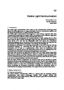
Fig. 1: Exact, lower and upper bounds capacities of amplitudeconstrained scalar Gaussian channels. A. Lower Bound
Figure 1 shows the exact, the lower and the upper bounds capacity versus the peak SNR of an amplitude-constrained Gaussian channel. It is seen that the upper bound and the lower bound in (3) are tight at low and hight peak SNR regimes, whereas the lower bound in (4) is tight at high SNR region only. Obviously, for two lower bounds, lim √A →0 CL1 = 0 and lim √A →0 CL2 = −∞. The following N0
For additive noise channels, one common way to derive a lower bound capacity is to use the Entropy Power Inequality (EPI) [31], [33] as CL1 = I(X; Y ) = h(Y ) − h(Y |X) = h(X + N ) − h(N ) " ! (EPI) 1 log e2h(X) + e2h(N ) − h(N ) ≥ 2 # $ 1 e2h(X) = log 1 + . 2 2πeN0
(6)
lim CU = 0,
N0
lim
(2)
From the above expression, it is straightforward to derive another bound as $ $ # # 1 1 2A2 2A2 > log CL2 ≥ log 1 + 2 πeN0 2 πeN0 $ # 2A = log √ . (4) 2πeN0 B. Upper Bound An upper bound for the capacity of a scalar Gaussian channel with an amplitude constraint is given by [35] α∈[0,1]
Proposition 1: Asymptotic behaviors of the upper bound √A →0
To make this bound as tight as possible, the distribution of X is chosen in such a way that maximizes the differential entropy h(X) under the amplitude constraint X ≤ |A|. According to the maximum entropy theorem [34], it is well-known that the uniform distribution is the maximum entropy probability distribution for a random variable under no constraint other than it is contained in the distribution’s support. It is thus reasonable to assume that X is uniformly distributed over [−A, A], resulting in $ # 1 2A2 . (3) CL1 = log 1 + 2 πeN0
CU = sup f (α),
N0
proposition proves the tightness of the upper bound at low and high peak SNR regimes.
(5)
√A →∞ N0
CU = log
#
√
2A 2πeN0
$
.
(7)
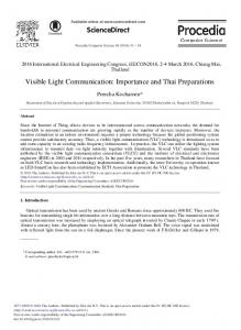
Proof: See Appendix A. III. MU-MISO VLC S YSTEM M ODEL A. MU-MISO VLC Channel Model Figure 2 illustrates the schematic diagram of a MU-MISO VLC system with NT LED arrays as transmitters and K decentralized single-photodiode users. For indoor VLC systems, there are generally two main types of link model, which are the direct light-of-sight (LOS) and the non-direct line-of-sight (NLOS). In most cases, only LOS link is taken into account since it accounts for more than 95% of the total received optical power at the receiver [38]. Quantitatively, even the strongest NLOS path component is at least 7 dB lower than the weakest LOS one [9]. For the sake of simplicity, we thus consider the LOS propagation path in this study. Let Hk ∈ R1×NT be the channel matrix between LED arrays and the k−th user % & (8) Hk = hk1 hk2 · · · hkNT , where hki represents the direct current (DC) gain between the k−th user and the i−th LED array. In practice, most LED sources have Lambertian beam distribution where the emission intensity is given as L(φ) =
l+1 cosl (φ), 2π
(9)
0090-6778 (c) 2016 IEEE. Personal use is permitted, but republication/redistribution requires IEEE permission. See http://www.ieee.org/publications_standards/publications/rights/index.html for more information.
This article has been accepted for publication in a future issue of this journal, but has not been fully edited. Content may change prior to final publication. Citation information: DOI 10.1109/TCOMM.2017.2691710, IEEE Transactions on Communications
4
d1
w1,1
d2
w1,2
!"!"!"!"
dK
d2 !"!"!"!"
dK
LED 1
w1,K
wNT ,1 wNT ,2 wNT ,K
k where IDC denotes the DC-bias for the k− LED array [15]. Since E[dk ] = 0, the signal sk does not affect the average illumination level of the LEDs. Instead, it is k . If we define x = uniquely determined by the DC-bias IDC &T % K×1 x1 x 2 . . . x K ∈ R as the transmitted signal % 1 & 2 K T IDC . . . IDC ∈ RK×1 as the vector and IDC = IDC aggregate DC bias vector, the received optical signal at the k−th user can be written as
Optical Modulation
User 1 !""!""!"""!""!""!"""!"
d1
x1
xNT
Optical Modulation
User K
Prk = Hk Ps ,
LED NT
Fig. 2: Schematic diagram of a MU-MISO VLC system. with φ is the angle of irradiance and l is the order of Lambertian emission determined by the semi-angle for half − log(2) illuminance of the LED Φ1/2 as l = log(cos Φ1/2 ) . For LOS link, hki is given by [38] ⎧ Ar ⎨ d2ki L(φ)Ts (ψki )g(ψki ) cos(ψki ) ,0 ≤ ψki ≤ Ψc , hki = ⎩ 0 , ψki > Ψc , (10)
where Ar and dki are the active area of the PD and the distance from the LED array to the PD, respectively. ψki is the angle of incidence, Ts (ψki ) is the gain of the optical filter and Ψc denotes the optical field of view (FOV) of the PD. g(ψki ) is the gain of the optical concentrator and given by ⎧ κ2 ⎨ sin2 Ψc , 0 ≤ ψki ≤ Ψc , (11) g(ψki ) = ⎩ 0 , ψki > Ψc , where κ is the refractive index of the concentrator. B. Precoding Model and Broadcast Transmission In the considered MU-MISO VLC system, NT LED arrays cooperate to broadcast information to K users simultaneously. This configuration can be regarded as a coordinated multipoint (CoMP) system for VLC communications [23]. In our study, a DC-biased PAM scheme is employed. In such scheme, a DC bias current IDC ∈ R+ which determines the brightness of the LEDs, is used to modulate a zero-mean data signal. Let di ∈ R %be the data symbol& intended for the iT th user, and d = d1 d2 . . . dK ∈ RK×1 be the data vector for all users. It is assumed that di is zero-mean, and without loss of generality, is normalized to the range of [−1, 1] [14]. At the k−th LED array, the broadcast signal sk which consists of data signals for all users, is generated from a% linear combination of the & data vector and the matrix Vk = wk,1 wk,2 . . . wk,K ∈ R1×K as sk = Vk d,
(12)
As a result, the transmitted signal xk can be expressed in the form of k , xk = sk + IDC
(13)
(14)
% &T where Ps = Ps1 Ps2 . . . PsNT ∈ RNT ×1 is the transmitted optical power vector of the LED arrays whose element Psk = ηxk is the transmitted optical power of the k−th LED arrays with η is the LED conversion factor. The received electrical signal at the k−th user after the opticalelectrical conversion is therefore given by yk = γPrk + nk = γηHk x + nk ⎞ ⎛ K , = γη ⎝Hk Wk dk +Hk Wi di +Hk IDC ⎠ +nk , (15) i=1,i̸=k
γ is the PD responsivity, Wk = %with &T w1,k w2,k . . . wNT ,k ∈ R%NT ×1 is the precoder &for the k−th user. If we define W = W1 W2 . . . WK ∈ RNT ×K% , it can be seen that &W can also be represented as T W = V1 V2 . . . VNT , where the k−th row vector is the precoder for the k−th LED array. As seen in (15), the first term Hk Wk dk is the desired /K signal, while the second term Hk i=1,i̸=k Wi di is the MUI. The third term Hk IDC represents the DC current for defining the illumination that carries no data and nk denotes the receiver noise, which is assumed to be additive white Gaussian noise (AWGN) with zero mean and variance σk2 , given by 1 0 σk2 = 2ePrk B +4πeAr γχamb 1−cos(Ψc ) B +i2amb B, (16) where e is the elementary charge, B denotes the system bandwidth and Prk = E[Prk ] = ηHk IDC is the average received optical power at the k−th user. i2amp is the pre-amplifier noise current density, χamp is the ambient light photocurrent. After removing the DC current by AC coupling, the received signal can be written by ⎞ ⎛ K , yk = γη ⎝Hk Wk dk + Hk Wi di ⎠ + nk . (17) i=1,i̸=k
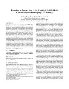
C. Amplitude Constraint on VLC Signal In this section, we briefly illustrate signal amplitude constraint in VLC systems, which is fundamentally different from their RF counterpart. It should be noted that the constraint, in turn, affects significantly the design of precoding matrices. As shown in Fig. 3, the LEDs exhibit a limited linear range, where the output optical power increases linearly from 0 to pmax in accordance with the input drive current from 0 to Imax . Hence, to guarantee normal operation of the LEDs, i.e., to avoid the overheating of the LEDs and the potential light
0090-6778 (c) 2016 IEEE. Personal use is permitted, but republication/redistribution requires IEEE permission. See http://www.ieee.org/publications_standards/publications/rights/index.html for more information.
This article has been accepted for publication in a future issue of this journal, but has not been fully edited. Content may change prior to final publication. Citation information: DOI 10.1109/TCOMM.2017.2691710, IEEE Transactions on Communications
5
Output Optical Power
%√ √ &T √ √ q1 q2 . . . qK ∈ RK×1 whose where q = i−th element represents the channel gain of the i−th user. We thus can express W in the form √ (25) W = H− diag{ q},
pmax DC-biasing point
pDC
IDC
0
Imax
where H− denotes the generalized inverse of H, which can be any matrix that satisfies HH− H = H. Generally, the generalized inverse H− is not unique. One of the special generalized inverse is the pseudo-inverse H† = HT (HHT )−1 , which is known to have minimal Frobenius norm among all the generalized inverses. Different from RF systems where the pseudo-inverse is the optimum precoder under the total average power constraint [16], we show that for VLC systems, it is not necessary to be the optimal solution under amplitude constraint of VLC signals. Assuming that H is full row-rank, any generalized inverse H− can be expressed by
Drive Current
Fig. 3: Nonlinear LED transfer characteristic. intensity reduction, the drive current xk for the k−th LED array must be constrained within the range of [0, Imax ] as k 0 ≤ sk + IDC ≤ Imax .
From (12) and since |dk | ≤ 1, we get 2 2 2 2 − 2 Vk 2 1 ≤ s k ≤ 2 Vk 2 1 .
(18) (19)
To ensure both (18) and (19), the following constraint should be imposed 2 2 2 V k 2 ≤ ∆k , (20) 1 ! " k k where ∆k = min IDC , Imax − IDC . We can write the above constraint with respect to Wi or W as K , 2 2 2[Wi ]k,: 2 ≤ ∆k , 1
(21)
i=1
or
2 2 2[W]k,: 2 ≤ ∆k . 1
H− = H† + PQ,
where P = I−H H is the orthogonal projection onto the null space of H and, Q is an arbitrary matrix. Plugging (26) into (25), the general structure of any ZF precoding matrix W is given by & % √ W = H† + PQ diag{ q}. (27)
This reduces the beamformer design problem for a certain performance metric to an optimization problem with respect to the q and the choice of generalized inverse H− via Q. In the next section, we investigate the optimal precoding designs for two typical performance measures in multiuser broadcast systems, namely: max-min fairness and maximum sum-rate. V. O PTIMAL B EAMFORMER D ESIGN
By removing the MUI via ZF precoders, the received signal at the k−th user simplifies to (22)
In this paper, depending on the targeted performance metric, either the expression in (21) or (22) will be considered in the design of the optimal precoding matrices.
yk = γηHk Wk dk + nk .
maximize
The goal of the transmit precoding is to mitigate the negative impact of the MUI term in the received signal (see (17)). In particular, the ZF precoding algorithm aims to completely remove the MUI via the construction of the precoder Wi in such a way that it is orthogonal to channel matrices of other users, i.e.,
subject to
∀ k ̸= i. (23) % T & T In other words, if we define H = H1 HT2 . . . HTK as an aggregate channel matrix, the ZF constraint in (23) implies that ⎤ ⎡√ q1 √ ⎥ ⎢ q2 √ ⎥ ⎢ HW = ⎢ (24) ⎥ = diag{ q}, . .. ⎣ ⎦ √ qK
(28)
The goal of the precoding design is to find Wk ’s that maximize a performance measure under the amplitude signal constraint in (22) and the ZF constraint in (24), i.e.,
IV. ZF P RECODING
Hk Wi = 0,
(26)
†
q≥0,W
f (q) √ HW = diag{ q}, 2 2 2[W]k,: 2 ≤ ∆k ∀ k, 1
(29)
where f (q) is the objective function that represents the performance measure of interest. Denoting Ck as the rate of the k−user, typical performance measures include [39] /K i) Sum rate: f (q) = k=1 Ck . /K ii) Proportional fairness: f (q) = k=1 log Ck . /K 1 iii) Harmonic mean: f (q) = 1/ k=1 Ck . iv) Max-min fairness: f (q) = min1≤k≤K Ck , with decreasing order of achievable sum rate and increasing order of user fairness. Since the closed-form expression for Ck is not available, we rely on the lower and upper bounds of Ck developed in Section II. Noted that dk ∈ [−1, 1], the amplitude input signal is hence constrained within the range of [−γηHk Wk , γηHk Wk ]. We
0090-6778 (c) 2016 IEEE. Personal use is permitted, but republication/redistribution requires IEEE permission. See http://www.ieee.org/publications_standards/publications/rights/index.html for more information.
This article has been accepted for publication in a future issue of this journal, but has not been fully edited. Content may change prior to final publication. Citation information: DOI 10.1109/TCOMM.2017.2691710, IEEE Transactions on Communications
6
therefore have the following lower and upper bounds for the rate of the k−th user $ # 1 2γηHk Wk WkT HTk 1 CL,k , (30) = log 1 + 2 πeσk2 9 ; 2γηHk Wk 2 : = log , (31) CL,k 2πeσk2 and
9
2γηHk Wk : CU,k = sup αk log 2πeσk2 αk ∈[0,1] " ! 3 − log αkαk (1 − αk ) 2 (1−αk ) ,
; (32)
The max-min fairness criterion aims to maximize the minimum rate among users. It leads to the following optimization problem q≥0,W
subject to
min Ck k
√ HW = diag{ q}, 2 2 2[W]k,: 2 ≤ ∆k ∀ k. 1
1) Lower Bound: From the lower bound in (30), it is 1 is proportional to qk /σk2 . Let us define σ = obvious that CL,k & % 2 2 T σ }−1 σ1 σ22 . . . σK and diag{q′ } = diag{q}diag{σ % & ′ ′ ′ T ′ where q = q1 q2 . . . qK . The optimization problem P1 can thus be rewritten as P2 :
maximize ′ q ≥0,W
subject to
min k
qk′
: √ HW = diag{ q′ }diag{ σ }, 2 2 2[W]k,: 2 ≤ ∆k ∀ k. 1
Following the similar argument in [16], we can search the optimal solution of the form q′ = q ′ 1 for some q ′ is optimal. To see this, let W∗ and q∗ be the optimal solution to P2 and variables q′ = q1 and W = < %:we define new : ∗ &= ∗ ∗ W diag q/q1 . . . q/qK , where q = mink qk∗ . Then, it holds that < %: : ∗ &= HW = HW∗ diag q/q1∗ . . . q/qK < %: : ∗ &= √ √ ∗ = diag{ q }diag{ σ }diag q/q1∗ . . . q/qK : √ (33) = diag{ q′ }diag{ σ },
and 2> < %: 2 2 ∗ 2[W]k,: 2 = 2 W diag q/q1∗ 2 1 2 2 ≤ 2[W∗ ]k,: 21 ,
...
q ≥0,Q
subject to
2 2 2% † & 2 2 ≤ ∆k ∀ k. q ′ σk2 2 + PQ H 2 k,: 2 1
′ It is easy to see that the optimal solution qopt is given by ′ qopt =
∆2 2% k & 2 2 22 maxk σk 2 H† + PQ k,: 2
(35)
1
A. Max-Min Fairness
maximize
q′ @
maximize ′
P3 :
where Q is the solution to
1 2 and CL,k are two lower bounds derived from (3) where CL,k and (4), respectively, while CU,k is the upper bound obtained from (5). Capitalizing on these bounds, we now investigate optimal precoding designs for two performance measures: the max-min fairness and the maximum sum-rate.
P1 :
since q/qk∗ ≤ 1 for all k. That is, W and q′ are also feasible and offer the same objective. We thus can reduce P2 to
: ∗ & =? 2 2 q/qK 2
k,: 1
(34)
P4 :
minimize Q,t
subject to
t
2% & 2 2 2 σk 2 H† + PQ k,: 2 ≤ t ∀ k. 1
The above problem is a linear programming, which has been extensively study [40] and can be solved efficiently by using standard optimization packages [42], [43]. 2) Upper Bound: For the upper bound, the optimization problem is given by P5 :
maximize
αk ∈[0,1],q′ ≥0,W
subject to
min CU,k k
: √ HW = diag{ q′ }diag{ σ }, ∥[W]k,: ∥1 ≤ ∆k ∀ k.
′ It is noted that CU,k is proportional # √to q$k since !the func′ 2γη qk √ tion f (αk , qk′ )αk ∈[0,1] = αk log − log αkαk (1 − 2πe " : 3 αk ) 2 (1−αk ) is monotonically increase with respect to qk′ for a fixed αk . Similar to the case of lower bound, we therefore can reduce problem P5 to
P6 :
maximize ′ q ≥0,Q
subject to
q′ @ 2% & 2 2 2 q ′ σk2 2 H† + PQ k,: 2 ≤ ∆k ∀ k, 1
which gives the same solution as in (35). Given the optimal ′ , an upper bound for the fairness rate CU of the solution qopt users is given by 9 : ′ ; ! " 2γη qopt 3 √ − log αkαk (1 − αk ) 2 (1−αk ) . CU = sup αk log 2πe αk ∈[0,1] (36) The solution for CU can be obtained efficiently using the bisection method as described in Section II. B. B. Maximum Sum-Rate In multiuser systems, another typical performance metric is the maximum sum-rate of all users, which gives the following optimization problem P7 :
maximize Wk
subject to
K ,
Ck
k=1
Hi Wk = 0 ∀ k ̸= i,
K , 2 2 2[Wi ]k,: 2 ≤ ∆k ∀ k. 1 i=1
0090-6778 (c) 2016 IEEE. Personal use is permitted, but republication/redistribution requires IEEE permission. See http://www.ieee.org/publications_standards/publications/rights/index.html for more information.
This article has been accepted for publication in a future issue of this journal, but has not been fully edited. Content may change prior to final publication. Citation information: DOI 10.1109/TCOMM.2017.2691710, IEEE Transactions on Communications
7
1) Lower Bound: First, considering the lower bound in (30), the sum-rate maximization problem is written as # $ K 1, 2γηHk Wk WkT HTk P8 : maximize log 1 + Wk 2 πeσk2
Algorithm 1 Iterative algorithm for solving problem P9 1:
Initialization 1) Estimate channel matrices Hk and noise variances σk2 . 2) Initialize qk to be positive and sufficiently small, e.g., qk = 0.1.
2:
Iteration: At the i−th iteration (i) (i−1) 1) Update qk , λk , Wk given qk by solving problem P10 using CVX toolbox . 2) i = i + 1.
3:
Termination: terminate the iteration when (i) (i−1) | ≤ ϵ, where ϵ = 10−3 is a predefined 1) |qk − qk threshold, or 2) i = L, where L = 10 is the predefined maximum number of iterations.
k=1
subject to
Hi Wk = 0 ∀ k ̸= i,
K , 2 2 2[Wi ]k,: 2 ≤ ∆k ∀ k. 1 i=1
It should be noted that the above problem is not a convex optimization problem with respect to Wk due to the nonconvexity of the objective function. Thus, it is generally difficult (if not impossible) to optimally solve it in reasonable time. We therefore attempt to study a sub-optimal solution by finding a local optimality. To do that, let us introduce slack √ variables λk and express Hk Wk = qk . Problem P8 is then rewritten as # $ K 1, 2γηλk log 1 + P9 : maximize Wk ,qk ,λk 2 πeσk2 k=1 < %√ √ &T = q1 . . . qK subject to HW = diag , K , 2 2 2[Wi ]k,: 2 ≤ ∆k ∀ k, 1 i=1
qk ≥ λk ∀ k,
Cauchy-Schwarz inequality. By replacing % second& con/K the straint in P8 by a stronger inequality as i=1 Wi WiT k,k ≤ ∆2k K ,
we obtain the following optimization problem, which yields a lower bound solution to problem P8 # $ K 1, 2γηHk Wk WkT HTk log 1 + P11 : maximize Wk 2 πeσk2 k=1
subject to
qk ≥ 0 ∀ k.
It can be seen that the objective function of the above problem is now concave. However, the constraint is& not = convex < %first √ √ T q1 . . . qK is consince HW is affine but diag cave. To deal with this issue, we adopt the convex-concave procedure (CCCP) [44], [45], which involves an iterative process, to find a local optimal solution. Specifically, at the i-th iteration of the procedure, we approximately linearize √ the concave term qk by using its Taylor expansion as @ ! " √ (i−1) (i−1) (i−1) qk ≈ qk + ! 1(i−1) qk − qk is the , where qk 2
qk
value of qk obtained from the previous iteration. As a result, problem P9 can be transformed to a convex optimization problem as problem P10 on the top of the next page. The detailed iterative algorithm for solving P9 is described in Algorithm 1. Due to the iterative nature, the Algorithm 1 usually requires several iterations to ensure a convergence of the solution. As a consequence, it may suffer from high computational time. We therefore present a simple lower bound solution for problem P8 with lower complexity. For this purpose, we rely on the following observation # $ 2 2 /K 2 2[Wi ]k,: 2 K i=1 , 1 ≤ [Wi WiT ]k,k ∀k. (37) K i=1
2 2 "2 2 [Wi ] 2 As proof, it is seen that = k,: 1 12 & 0 /K /K % /K T 2 and i=1 Wi Wi k,k = i=1 wk,i . Hence, i=1 |wk,i | the inequality in (37) can be obtained directly from the !/
K i=1
Hi Wk = 0 ∀ k ̸= i, K , %
Wi WiT
i=1
&
k,k
≤
∆2k ∀ k. K
Obviously, the tightness of this bound depends on the tightness of the inequality in (37), which is inversely proportional to the number of users. As illustrated in Section VI, a very tight lower bound solution to problem P8 can be achieved when K = 2. For larger values, e.g., K = 3 and 4, acceptable lower bounds can still be obtained. Now, to solve problem P11, let us define Gi = Wi WiT ≻ 0, resulting in K
P12 :
maximize Gk
1, log 2 k=1
#
2γηHk Gk HTk 1+ πeσk2
$
subject to Hi Gk HTi = 0 ∀ k ̸= i, K , % i=1
Gi ]k,k ≤
∆2k ∀ k, K
rank(Gk ) = 1 ∀ k. The objective function and the first two constraints of the above problem are convex with respect to Gk . Unfortunately, the third constraint is not convex. To overcome this difficulty, we first omit that constraint to obtain $ # K 1, 2γηHk Gk HTk log 1 + P13 : maximize Gk 2 πeσk2 k=1
subject to Hi Gk HTi = 0 ∀ k ̸= i, K , % i=1
Gi ]k,k ≤
∆2k ∀ k. K
0090-6778 (c) 2016 IEEE. Personal use is permitted, but republication/redistribution requires IEEE permission. See http://www.ieee.org/publications_standards/publications/rights/index.html for more information.
This article has been accepted for publication in a future issue of this journal, but has not been fully edited. Content may change prior to final publication. Citation information: DOI 10.1109/TCOMM.2017.2691710, IEEE Transactions on Communications
8
maximize (i)
Wk ,qk ,λk
subject to
#
$ 2γηλk πeσk2 k=1 A B@ (i−1) q1 + HW = diag K
P10 :
1, log 2
1+
K , 2 2 2[Wi ]k,: 2 ≤ ∆k ∀ k, 1
i=1 (i) qk ≥ (i) qk ≥
!1 (i−1) 2 q1
maximize Wk
subject to
q1 −
K ,
log
k=1
9
2γηHk Wk : 2πeσk2
;
Hi Wk = 0 ∀ k ̸= i,
P16 :
!
qK −
(i−1) qK
"CT D
,
K ,
αk log
k=1
− log
!
9
2γηHk Wk : 2πeσk2
αkαk (1
− αk )
Hi Wk = 0 ∀ k ̸= i,
;
3 2 (1−αk )
K , 2 2 2[Wi ]k,: 2 ≤ ∆k ∀ k. 1
maximize αk ∈[0,1]
K ,
f (αk ),
k=1
$ # √ k W2 k − where f (αk ) = αk log 2γηH 2πeσk ! " 3 log αkαk (1 − αk ) 2 (1−αk ) . Obviously, the optimal solution for problem P16 is achieved when each summand f (αk ) of the objective function is maximized. Therefore, by solving optimal solutions for αk using the bisection method, a solution for P15 can easily be obtained. The proposed iterative algorithm is summarized in Algorithm2 as follows
1:
Initialization 1) Estimate channel matrices Hk and noise variances σk2 . (0) (0) 2) Initialize precoding matrices Wk , e.g., Wk = 0.
2:
Iteration: At the i−th iteration (i) (i−1) by solving problem P16 1) Update αk given Wk using the bisection method. (i) 2) With the obtained αk , solve problem P15 to update (i) Wk by using CVX toolbox. 3) i = i + 1.
3:
Termination: terminate the iteration when (i) (i−1) 2 1) ∥Wk − Wk ∥F ≤ ϵ, where ϵ = 10−3 is a predefined threshold, or 2) i = L, where L = 10 is the predefined maximum number of iterations.
2) Upper Bound: The sum-rate optimization problem with the use of the upper bound (32) can be written as
subject to
!1 (i−1) 2 qK
Algorithm 2 Iterative algorithm for optimizing Wk and αk
The above optimization problem is also a MAXDET program subject to linear matrix inequalities. It therefore can be solved by using standard optimization packages.
maximize
...
@ (i−1) qK +
fixed, problem reduces to
i=1
αk ∈[0,1],Wk
"
0 ∀ k.
K , 2 2 2[Wi ]k,: 2 ≤ ∆k ∀ k. 1
P15 :
(i−1) q1
λk ∀ k,
It can be seen that problem P13 is a standard determinant maximization (MAXDET) program subject to linear matrix inequalities [41], which can be solved efficiently by using standard optimization packages. An important question now is that whether the optimal solution of P13 is also optimal to P11. Interestingly in [16], it is proved that the rank-one constraint in P11 always holds. In other words, problems P13 and P11 are equivalent and thus they have the same solution. Now, we examine the use of the lower bound in (4), which accordingly leads to
P14 :
!
"
i=1
The objective function of problem P15 is concave with respect to Wk and αk . However, due to the special form of the objective function (containing a product of an affine and a concave function), most of standard optimization packages can not be used directly to solve P15. To overcome this issue, we use an iterative approach. In particular, we iteratively optimize Wk and αk while fixing the other variable. Fixing αk , problem can be solved using CVX. On the other hand, when Wk are
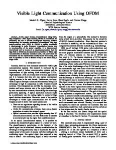
VI. N UMERICAL R ESULTS & D ISCUSSIONS This section presents numerical results to illustrate the theoretical analyses of the max-min fairness and the maximum sum-rate performances. Figure 4 shows the geometrical configuration of the considered MU-MISO VLC system, which consists of 4 LED arrays. We assume that all receivers are placed on the same receive plane, which is 0.5 m above the floor. In addition, for the sake of convenience, a Cartesian
0090-6778 (c) 2016 IEEE. Personal use is permitted, but republication/redistribution requires IEEE permission. See http://www.ieee.org/publications_standards/publications/rights/index.html for more information.
This article has been accepted for publication in a future issue of this journal, but has not been fully edited. Content may change prior to final publication. Citation information: DOI 10.1109/TCOMM.2017.2691710, IEEE Transactions on Communications
9
Table I: MU-MISO VLC System Parameters Parameter
z
Value 1
Room and LED configurations Room Dimension (Length × Width × Height) Number of LED arrays, NT LED array size Number of LED chips per array LED array positions
LED arrays
3
5 (m) × 5 (m) × 3 (m)
2
4
Room Height = 3 m
4
0.1 (m) × 0.1 (m)
Receive plane
36
array array array array
1 2 3 4
: : : :
√ √ (− √ 2, 3) √ 2, − 2, −√2, 3) ( √ (− √ 2,√ 2, 3) ( 2, 2, 3)
LED bandwidth, B
20 MHz
LED beam angle, φ (LED Lambertian order is 1)
120◦
LED conversion factor, η
0.44 W/A
Receiver photodetectors PD active area, Ar
1 cm2
PD responsivity, γ
0.54 A/W
PD field of view (FOV), Ψc
60◦
Optical filter gain, Ts (ψ)
1
Refractive index of the concentrator, κ
1.5
User 1 User 2
y
60
Preamplifier noise current density, iamb
5 pA/Hz−1/2
coordinate system whose the origin is the center of the floor is used for specifying the positions of users and the LED arrays. Unless otherwise noted, the parameters of the room, LED arrays and optical receivers are given in Table I. Furthermore, all analytical results are obtained by averaging 10, 000 different channel realizations (10, 000 different positions of users are uniformly placed on the receive plane). First, we compare the pseudo-inverse with the generalized inverse design in terms of the max-min fairness performance. The purpose is to validate our argument that, unlike its RF counterpart, the pseudo-inverse, which was studied in previous works [25], [26], may not necessarily result in the optimal solution in MU-MISO VLC system due to the amplitude constraint. In Fig. 5, we present the: averaged normalized fairness ′ , versus the number of power, which is defined as γη qopt LED arrays for different optimal designs of precoding matrix: the generalized inverse and the pseudo inverse. The number of users is set to K = 2 and the average transmitted power per LED array is set to 30 dBm. In addition, because the positions of LED arrays have an impact on the performance, for the sake of comparison, we assume that LED arrays are placed on a 2 meter radius circle so that the center points of them form a regular polygon as in Fig. 6 for the scenarios of NT = 2, 3, 5 and 6 (the case of NT = 4 was specified in Table I). It is seen that the generalized inverse precoding clearly outperforms the pseudo inverse, especially when the number
Room Length = 5 m
Generalized Inverse Pseudo Inverse
50 Fairness Power γηq’
10.93 A/(m2 · Sr)
x
Room Width = 5 m
Fig. 4: Geometrical configuration of a MU-MISO VLC system with 4 LED arrays and 2 users.
Other parameters Ambient light photocurrent, χamb
O
0.5 m
40
30
20
10 2
3
4 Number of LED Arrays NT
5
6
Fig. 5: Averaged normalized fairness power for different precoding matrix designs: generalized inverse and pseudo inverse.
of LED arrays is lager than the number of users. Particularly, the pseudo inverse becomes drastically inferior to the optimal design as the number of LED arrays increases. This is because the pseudo inverse design restricts the search for the optimal solution into a much smaller feasible subset, i.e., restricting Q = 0. Next, Figs. 7, 8 and 9 present the averaged sum max-min fairness capacity versus the average LED array power Ps for 2-, 3-, and 4-user scenarios, respectively, with generalized and pseudo inverses. The average LED array power ranges from 20 to 40 dBm, which corresponds to 0.1 to 10 W. As expected from the previous figure, the generalized inverse performs better than the pseudo inverse does in all cases, especially
0090-6778 (c) 2016 IEEE. Personal use is permitted, but republication/redistribution requires IEEE permission. See http://www.ieee.org/publications_standards/publications/rights/index.html for more information.
This article has been accepted for publication in a future issue of this journal, but has not been fully edited. Content may change prior to final publication. Citation information: DOI 10.1109/TCOMM.2017.2691710, IEEE Transactions on Communications
10
y
y
12
O
O
x
0.5 m
x
0.5 m 3
2
0.5 m
0.5 m
(a) 2 LED array setup
(b) 3 LED array setup
y
y
1
5
2
1 2
O
x 0.5 m
2
O
6
3
Averaged Fairness Capacity (nats/s/Hz)
1
1
10
8
6
4
2
0 20
x
25 30 35 Average LED Array Power Ps (dBm)
0.5 m 4
3
5
(c) 5 LED array setup
0.5 m
(d) 6 LED array setup
Fig. 6: Examples of LED array setup.
10 Averaged Fairness Capacity (nats/s/Hz)
12
Generalized Inverse Pseudo Inverse
10
8
6
4
Generalized Inverse Pseudo Inverse
8 1.662 1.658
6 1.654 27.9927.995 28 28.005
4 7.22 7.21
2
25 30 35 Average LED Array Power P (dBm)
40
s
Fig. 7: Averaged sum max-min fairness rate versus average LED array power: 2 users.
in the high power regime. Nevertheless, it is seen that the superiority of the generalized inverse over the pseudo inverse decreases with an increase in the number of users. Especially, when the numbers of users and LED arrays are the same, i.e., NT = K = 4 in Fig. 9 or when NT = 2 = K in Fig. 5, the performances of the generalized inverse precoding and the pseudo inverse precoding are almost identical. We demonstrate in Figs. 10, 11 and 12 the averaged sum capacity versus the average LED array power for 2-, 3and 4-user scenarios, respectively. Firstly, as expected from Proposition 1, all the bounds asymptotically converge at high transmitted power. It is observed that the rate of convergence
7.2 35.96 35.98 36 36.02
0 20
2 20
40
Fig. 8: Averaged sum max-min fairness rate versus average LED array power: 3 users.
4
0.5 m
Averaged Min−Max Capacity (nats/s/Hz)
Generalized Inverse Pseudo Inverse
25 30 35 Average LED Array Power Ps (dBm)
40
Fig. 9: Averaged sum max-min fairness rate versus average LED array power: 4 users.
is inversely proportional to the number of users, which is an obvious consequence of the sum-rate performance. Secondly, for the whole range of transmitted LED array power, the lower bound in P8 is tight compared to the lower bound in P11 with maximum gaps are 0.4 nat and 0.5 nat for 3 and 4 user scenarios, respectively, (the gap is negligible when there are 2 users). On the other hand, the lower bound in P14 is applicable in the high transmitted power only for the case of 3 and 4 users. In Fig. 13a and Fig. 13b, the convergence behaviors of Algorithm 1 and Algorithm 2 for different numbers of users are presented, respectively. The average transmitted LED array power is set to 40 dBm. Specifically, at a targeted relative sum-rate error of ϵsum-rate = 10−3 , the Algorithm 1 requires 5 iterations for all cases of the number of users. For the case
0090-6778 (c) 2016 IEEE. Personal use is permitted, but republication/redistribution requires IEEE permission. See http://www.ieee.org/publications_standards/publications/rights/index.html for more information.
This article has been accepted for publication in a future issue of this journal, but has not been fully edited. Content may change prior to final publication. Citation information: DOI 10.1109/TCOMM.2017.2691710, IEEE Transactions on Communications
11
8
6
4
2 20
25 30 35 Average LED Array Power P (dBm)
10
8
6
4
2
0 20
40
s
Algorithm 1
10 Lower Bound P8 Lower Bound P11 Lower Bound P14 Upper Bound P15
0
10 8 6 4
Algorithm 2
2
10
2 Users 3 Users 4 Users
2 Users 3 Users 4 Users
0
10 Relative Sum−rate Error
Average Maximum Sum−Rate (nats/s/Hz)
40
Fig. 12: Averaged sum-rate maximization versus average LED array power: 4 users.
2
12
25 30 35 Average LED Array Power P (dBm) s
Fig. 10: Averaged sum-rate maximization versus average LED array power: 2 users.
14
Lower Bound P8 Lower Bound P11 Lower Bound P14 Upper Bound P15
10 Relative Sum−rate Error
10
12
Lower Bound P8 Lower Bound P11 Lower Bound P14 Upper Bound P15
Averaged Maximum Sum−Rate (nats/s/Hz)
Averaged Maximum Sum−Rate (nats/s/Hz)
12
−2
10
−4
10
−6
−2
10
−4
10
−6
10
10
2 −8
0 20
10 25 30 35 Average LED Array Power P (dBm)
40
s
Fig. 11: Averaged sum-rate maximization versus average LED array power: 3 users.
of the Algorithm 2, it needs 2, 3 and 6 iterations when the number of users are 2, 3 and 4, respectively, to obtain the relative sum-rate error of 10−3 . VII. C ONCLUSIONS The paper studied optimal precoding designs for MU-MISO VLC systems with practical constraints of the optical signal. To mitigate the MUI among users, ZF precoding technique is utilized due to its computational advantage. Unlike previous studies, optimal ZF precoding matrices are designed in accordance with specific performance criterions. Capitalizing on the precoding designs, lower and upper bounds of the max-min fairness and the maximum sum-rate are derived. Numerical results showed that the generalized inverse design achieves
0
−8
2 4 6 8 Number of Iterations L (a)
10
10
0
2 4 6 8 Number of Iterations L (b)
10
Fig. 13: (a) Convergence behavior of Algorithm 1, (b) Convergence behavior of Algorithm 2.
better performance than that of the pseudo inverse design, especially in the high SNR region. A PPENDIX A P ROOF OF P ROPOSITION 1 The first derivative of f (α) is given by # $ 3 2A 1 ′ f (α) = log √ −log(α)+ log(1 − α)+ . (38) 2 2 2πeN0
Since f ′ (α) is continuous, monotonically decreasing over (0, 1), limα→0 f ′ (α) = ∞ and limα→1 f ′ (α) = −∞, the critical point α∗ exists and is unique. At the critical point $ # 1 3 2A ∗ ∗ ∗ + . f1 (α ) = log(α )− log(1−α ) = log √ 2 2 2πeN0 (39)
0090-6778 (c) 2016 IEEE. Personal use is permitted, but republication/redistribution requires IEEE permission. See http://www.ieee.org/publications_standards/publications/rights/index.html for more information.
This article has been accepted for publication in a future issue of this journal, but has not been fully edited. Content may change prior to final publication. Citation information: DOI 10.1109/TCOMM.2017.2691710, IEEE Transactions on Communications
12
As lim log
√A →0 N0
lim
√A →∞
#
log
N0
√
#
2A 2πeN0
√
$
2A 2πeN0
+
$
1 = −∞, 2
(40)
1 = ∞, 2
(41)
+
lim f1 (α∗ ) = −∞,
α∗ →0
(42)
∗
(43)
lim f1 (α ) = ∞
α∗ →1
and f1 (α∗ ) is continuous, monotonically increasing, we deduce to lim α∗ = 0 and
√A →0 N0
lim
√A →∞
α∗ = 1.
(44)
N0
As a result (45)
lim CU = f (0) = 0,
√A →0 N0
lim
√A →∞ N0
CU = f (1) = log
#
2A √ 2πeN0
$
.
(46)
This completes the proof. R EFERENCES [1] A. Nuwanpriya, S.-W. Ho, C. S. Chen, “Indoor MIMO visible light communications: novel angle diversity receivers for mobile users,” IEEE J. Sel. Areas Commun., vol. 33, no. 9, pp. 1780–1792, May 2015. [2] P. H. Pathak, X. Feng, P. Hu, and P. Mohapatra, “Visible light communication, networking, and sensing: a survey, potential and challenges,” IEEE Commun. Surveys Tuts., vol. 17, no. 4, pp. 2047–2077, Sept. 2015. [3] A. Jovicic, L. Junyi, T. Richardson, “Visible light communication: opportunities, challenges and the path to market,” IEEE Commun. Mag., vol. 51, no. 12, pp. 26–32, Dec. 2013. [4] A. C. Boucouvalas, P. Chatzimisios, Z. Ghassemlooy, M. Uysal, K. Yiannopoulos, “Standards for indoor optical wireless communications,” IEEE Commun. Mag., vol. 53, no. 3, pp. 24-31, Mar. 2015. [5] IEEE Std 802.15.7, IEEE Standard for Local and metropolitan area networks - Part 15.7: Short-range wireless optical communication using visible light, Mar. 2011. [6] P. A. Haigh, Z. Ghassemlooy, S. Rajbhandari, I. Papakonstantinou, and W. Popoola, “Visible light communications: 170 Mb/s using an artificial neural network equalizer in a low bandwidth white light configuration,” J. Lightw. Technol., vol. 32, no. 9, pp. 1807–1813, Apr. 2014. [7] D. A. Basnayaka, H. Haas, “Hybrid RF and VLC systems: improving user data rate performance of VLC systems,” in Proc. IEEE Vehicular Technology Conference (VTC-Spring), pp. 1–5, May 2015. [8] J. H. Yoo, S. Y. Jung, “Multi-coded variable PPM with level cutting for high data rate visible light communications,” in Proc. Asia-Pacific Conference on Communication (APCC), pp. 703–708, Oct. 2012. [9] L. Zeng, D. C. O’Brien, H. L. Minh, G. E. Faulkner, K. Lee, D. Jung, Y. Oh, E. T. Won, “High data rate multiple input multiple output (MIMO) optical wireless communications using white LED lighting,” IEEE J. Sel. Areas Commun., vol. 27, no. 9, pp. 1654–1662, Dec. 2009. [10] T. Fath, H. Haas, “Performance comparison of MIMO techniques for optical wireless communications in indoor environments,” IEEE Trans. Commun., vol. 61, no. 2, pp. 733–742, Feb. 2013. [11] L. Wu, Z. Zhang and H. Liu, “MIMO-OFDM visible light communications system with low complexity,” in Proc. IEEE Int. Conf. Communications (ICC), pp. 3933–3937, June 2013. [12] A. Burton, H. L. Minh, Z. Ghassemlooy, E. Bentley, C. Botella, “Experimental demonstration of 50-Mb/s visible light communications using 4 × 4 MIMO,” IEEE Photon. Technol. Lett., vol. 26, no. 9, pp. 945–948, May 2014. [13] A. H. Azhar, T. Tran, D. O’Brien, “A gigabit/s indoor wireless transmission using MIMO-OFDM visible-light communications,” IEEE Photon. Technol. Lett., vol. 52, no. 2, pp. 171–174, Jan. 2013.
[14] K. Ying, H. Qian, R. J. Baxley, G. T. Zhou, “MIMO transceiver design in dynamic-range-limited VLC systems,” IEEE Photon. Technol. Lett., vol. 28, no. 22, pp. 2593–2596, Nov. 2016. [15] K. Ying, H. Qian, R. J. Baxley, S. Yao, “Joint optimization of precoder and equalizer in MIMO VLC systems,” IEEE J. Sel. Areas Commun., vol. 33, no. 9, pp. 1948–1958, May 2015. [16] A. Wiesel, Y. C. Eldar, S. Shamai, “Zero-forcing precoding and generalized inverses,” IEEE Trans. Signal Process, vol. 56, no. 9, pp. 4409– 4418, Sept. 2008. [17] Q. H. Spencer, A. L. Swindlehurst, M. Haardt, “Zero-forcing methods for downlink spatial multiplexing in multiuser MIMO channels,” IIEEE Trans. Signal Process., vol. 52, no. 2, pp. 461–471, Feb. 2004. [18] C. B. Peel, B. M. Hochwald, A. L. Swindlehurst, “A vector-perturbation technique for near-capacity multiantenna multiuser communication-part I: channel inversion and regularization,” IEEE Trans. Commun., vol. 53, no. 1, pp. 195–202, Jan. 2005. [19] V. Stankovic, M. Haardt, “Generalized design of multi-user MIMO precoding matrices,” IEEE Trans. Wireless Commun., vol. 7, no. 3, pp. 953–961, Mar. 2008. [20] H. Yang, J. Chen, Z. Wang, C. Yu, “Performance of a precoding MIMO system for decentralized multiuser indoor visible light communications,” IEEE Photon. J., vol. 5, no. 4, Aug. 2013, Art. ID 7800211. [21] J. Chen, N. Ma; Y. Hong, C. Yu, “On the performance of MU-MIMO indoor visible light communication system based on THP algorithm,” in Proc. IEEE/CIC Int. Conf. on Communications in China, pp. 136–140, Oct. 2014. [22] T. V. Pham, H. L. Minh, Z. Ghassemlooy, T. Hayashi, A. T. Pham, “Sumrate maximization of multi-user MIMO visible light communications,” in Proc. IEEE Int. Conf. on Communications (ICC), Visible Light Communication and Networking Workshop, pp. 1344–1349, June 2015. [23] H. Ma, L. Lampe, S. Hranilovic, “Coordinated broadcasting for multiuser indoor visible light communication systems,” IEEE Trans. Commun., vol. 63, no. 9, pp. 3313–3324, Sept. 2015. [24] B. Li, J. Wang, R. Zhang, H. Shen, C. Zhao, L. Hanzo, “Multiuser MISO transceiver design for indoor downlink visible light communication under per-LED optical power constraints,” IEEE Photon. J., vol. 7, no. 4, Aug. 2015, Art. ID 7201415. [25] Z. Yu, R. Baxley, G. T. Zhou, “Multi-user MISO broadcasting for indoor visible light communication,” in Proc. IEEE Int. Conf. on Acoustics, Speech and Signal Processing (ICASSP), pp. 4849–4853, May 2013. [26] T. Cogalan, H. Haas, E. Panayirci, “Precoded single-cell multi-user MISO visible light communications,” in Proc. European Wireless Conference, pp. 1–6, May 2015. [27] T. V. Pham, A. T. Pham, “Max-min fairness and sum-rate maximization of MU-VLC local networks,” in Proc. of IEEE Telecommunications Conference (GLOBECOM), Optical Wireless Communication Workshop, pp. 1–6, Dec. 2015. [28] T. V. Pham, A. T. Pham, “On the secrecy sum-rate of MU-VLC broadcast systems with confidential messages,” in Proc. of the International Symposium on Communication Systems, Networks and Digital Signal Processing (CSNDSP), July. 2016. [29] K-H. Park, Y-C. Ko, M. Alouini, “On the power and offset allocation for rate adaptation of spatial multiplexing in optical wireless MIMO channels,” IEEE Trans. Commun., vol. 61, no. 4, pp. 1535 – 1543, Apr. 2013. [30] J. G. Smith, “The information capacity of amplitude and varianceconstrained scalar Gaussian channels,” J. Inf. Control, vol. 18, no. 3, pp. 203–219, Apr. 1971. [31] A. Lapidoth, S. M. Moser, M. A. Wigger, “On the capacity of free-space optical intensity channels,” IEEE Trans. Inf. Theory, vol. 55, no. 10, pp. 4449–4461, Oct. 2009. [32] A. A. Farid, S. Hranilovic, “Capacity bounds for wireless optical intensity channels with Gaussian noises,” IEEE Trans. Inf. Theory, vol. 56, no. 12, pp. 6066–6077, Dec. 2010. [33] C. E. Shannon, “A mathematical theory of communication,” Bell Syst. Tech. J., vol. 27, no. 3, pp. 379–423, July 1948. [34] T. Cover, J. Thomas, “Elements of information theory,” Wiley Interscience, 2006. [35] A. Chaaban, J. M. Morvan, M.-S. Alouini, “Free-space optical communications: capacity bound, approximations, and a new sphere-packing perspective,” IEEE Trans. Commun., vol. 64, no. 3, pp. 1176–1191, Mar. 2016. [36] T. Young, M. J. Mohlenkamp, “Introduction to numerical methods and matlab programming for engineers,” Department of Mathematics, Ohio University, 2015.
0090-6778 (c) 2016 IEEE. Personal use is permitted, but republication/redistribution requires IEEE permission. See http://www.ieee.org/publications_standards/publications/rights/index.html for more information.
This article has been accepted for publication in a future issue of this journal, but has not been fully edited. Content may change prior to final publication. Citation information: DOI 10.1109/TCOMM.2017.2691710, IEEE Transactions on Communications
13
[37] Y. Tanaka, T. Komine, S. Haruyama, M. Nakagawa, “Indoor visible light data transmission system utilizing white LED lights,” IEICE Trans. Commun., vol. E86-B, no.8, pp.2440–2454, Aug. 2003. [38] T. Komine, M. Nakagawa, “Fundamental analysis for visible-light communication system using LED lights,” IEEE Trans. Consum. Electron., vol. 50, no. 1, pp. 100–107, Feb. 2004. [39] Z. Q. Luo, S. Zhang, “Dynamic spectrum management: complexity and duality,” IEEE J. Sel. Topics Signal Process., vol. 2, no. 1, pp. 57–73, Feb. 2008. [40] S. Boyd, L. Vandenberghe, “Convex Optimization,” Cambridge University Press, 2004. [41] L. Vandenberghe, S. Boyd, S. P. Wu, “Determinant maximization with linear matrix inequality constraints,” SIAM J. Matrix Anal. Appl., vol. 19, no. 2, pp. 499–533, Apr. 1998. [42] M. Grant, S. Boyd, “CVX: Matlab software for disciplined convex programming version 2.1,” http://cvxr.com/cvx/, Jan. 2015. [43] J. Lofberg, “YALMIP : a toolbox for modeling and optimization in MATLAB,” IEEE Int. Symp. on Computer Aided Control Systems Design, pp. 284–289, Sept. 2004. [44] A. L. Yuille, A. Rangarajan, “The Concave-Convex Procedure (CCCP),” Neural Comput., vol. 15, no. 4, pp. 915–936, Apr. 2003. [45] B. K. Sriperumbudur, G. R. G. Lanckriet “On the Convergence of the Concave-Convex Procedure,” Neural Inf. Process. Syst., pp. 1–9, 2009.
Thanh V. Pham received the B.E. and M.E. degrees in Computer Network Systems from the University of Aizu, Japan in 2014 and 2016, respectively. He is currently studying toward a Ph.D. degree also at the University of Aizu. His study in Japan is funded by Japanese government scholarship (MonbuKagakusho). His research interests are in the area of freespace optics (FSO), relay networks and Visible Light Communications (VLC). Thanh is a student member of IEEE and IEICE.
Hoa Le-Minh was a Researcher with Siemens AG, Munich, Germany, in 2002 and with the University of Oxford, U.K., in 2010. Since 2010, he has been with the Northumbria University, U.K., where he served as a Senior Lecturer (in 2010) and then as a Program Leader of electrical and electronics engineering (in 2013). He is the author of over 100 papers published in referred journals and conferences. His research interests include optical communications, visible-light communications, and smartphone technology. He currently serves as the Vice-Chair for IEEE Communications Chapter of U.K. and Ireland, and serves as a Guest Editor for IET and ETT journals.
Anh T. Pham received the B.E. and M.E. degrees, both in Electronics Engineering from the Hanoi University of Technology, Vietnam in 1997 and 2000, respectively, and the Ph.D. degree in Information and Mathematical Sciences from Saitama University, Japan in 2005. From 1998 to 2002, he was with the NTT Corp. in Vietnam. Since April 2005, he has been on the faculty at the University of Aizu, where he is currently Professor and Head of Computer Communications Laboratory with the Division of Computer Engineering. Dr. Pham’s research interests are in the broad areas of communication theory and networking with a particular emphasis on modeling, design and performance evaluation of wired/wireless communication systems and networks. He has authored/coauthored more than 150 peer-reviewed papers on these topics. Dr. Pham is senior member of IEEE. He is also member of IEICE and OSA.
0090-6778 (c) 2016 IEEE. Personal use is permitted, but republication/redistribution requires IEEE permission. See http://www.ieee.org/publications_standards/publications/rights/index.html for more information.