Jan 16, 2018 - 2 Visible Light Communication for Automotive Applications ...... by the market leaders â Velodyne, Quanergy, LeddarTech or Continental AG â ...
Visible Light Range-Finding and Communication Using the Automotive LED Lighting Bastien Béchadergue
To cite this version: Bastien Béchadergue. Visible Light Range-Finding and Communication Using the Automotive LED Lighting. Signal and Image processing. Université Paris Saclay, 2017. English.
HAL Id: tel-01685450 https://hal.archives-ouvertes.fr/tel-01685450 Submitted on 16 Jan 2018
HAL is a multi-disciplinary open access archive for the deposit and dissemination of scientific research documents, whether they are published or not. The documents may come from teaching and research institutions in France or abroad, or from public or private research centers.
L’archive ouverte pluridisciplinaire HAL, est destinée au dépôt et à la diffusion de documents scientifiques de niveau recherche, publiés ou non, émanant des établissements d’enseignement et de recherche français ou étrangers, des laboratoires publics ou privés.
NNT : 2017SACLV085
Mesure de distance et transmission de données intervéhicules par phares à LED Thèse de doctorat de l'Université Paris-Saclay préparée à l’Université de Versailles Saint-Quentin-enYvelines
École doctorale n°580 Sciences et Technologies de l’Information et de la Communication (STIC) Spécialité de doctorat: Traitement du signal et des images
Thèse présentée et soutenue à Vélizy-Villacoublay, le 10 novembre 2017, par
Bastien Béchadergue
Composition du Jury : Mme. Véronique Vèque Professeure, Université Paris-Sud (L2S)
Présidente
Mme. Anne Julien-Vergonjanne Professeure, Université de Limoge (XLIM)
Rapportrice
M. Thierry Bosch Professeur, INP de Toulouse (LAAS)
Rapporteur
M. Dominic O’Brien Professeur, Université d’Oxford
Examinateur
M. Fawzi Nashashibi Directeur de recherche, INRIA (RITS)
Examinateur
M. Luc Chassagne Professeur, Université Paris-Saclay, UVSQ (LISV)
Directeur de thèse
M. Hongyu Guan Ingénieur de recherche, Université Paris-Saclay, UVSQ (LISV)
Co-Directeur de thèse
M. Jean-Laurent Franchineau Directeur de programme, Institut Vedecom
Invité
Titre : Mesure de distance et transmission de données inter-véhicules par phares à LED Mots clés : communication optique sans fil, mesure de distance, véhicule autonome, LiFi Résumé : En réponse aux problèmes croissants liés aux transports routiers - accidents, pollutions, congestions - les véhicules à faibles émissions, équipés de systèmes de transports intelligents (ITS) sont progressivement développés. Si la finalité de cette démarche est le véhicule entièrement autonome, on peut néanmoins s'attendre à voir d'abord sur nos routes des véhicules automatisés sur des phases de conduite spécifiques. C'est le cas du convoi automatisé, qui permet à plusieurs véhicules de rouler en convois de manière automatique et donc d'augmenter la capacité des voies de circulation tout en réduisant la consommation de carburant. La fiabilité de cet ITS repose sur plusieurs briques technologiques, et en particulier sur la mesure de distance et la transmission de données véhicule-véhicule (V2V). De nombreux systèmes permettent de réaliser ces deux fonctions vitales comme, par exemple, les radars ou lidars pour la mesure de distance et la technologie IEEE 802.11p pour la communication véhiculaire. Si ces différents dispositifs présentent de très bonnes performances, ils sont néanmoins particulièrement sensibles aux interférences, qui ne cessent de se multiplier à mesure que le nombre de véhicules équipés augmente et que le trafic est dense. Pour pallier les dégradations de performances induites par de telles situations, des technologies complémentaires pourraient donc être utiles. Le récent développement des diodes électroluminescentes (LED) blanches, en particulier pour l'éclairage automobile, a permis l'émergence des communications optiques visibles sans fil (VLC). Les phares à LED sont alors utilisés pour transmettre des données entre véhicules et avec les infrastructures. Malgré la puissance limitée de ces éclairages, plusieurs études ont montré qu'une transmission de qualité est possible sur quelques dizaines de mètres, faisant de la VLC un complément particulièrement intéressant à l'IEEE 802.11p, en particulier pour les convois automatisés. Par analogie, on peut alors se demander si les phares ne pourraient pas être aussi utilisés pour mesurer la distance V2V. Le but de cette thèse est donc de proposer et évaluer un système dédié aux situations de convois automatisés qui, à partir des phares avant et arrière des véhicules, transmet des données et mesure simultanément la distance V2V. Dans un premier temps, une étude détaillée de l'état de l'art de la VLC pour la communication V2V est effectuée afin de déterminer l'architecture de base de notre système. La fonction de mesure de distance est ensuite ajoutée, après une revue des différentes techniques usuelles. Une fois l'architecture générale du système établie, elle est dans un premier temps validée par des simulations avec le logiciel Simulink. En particulier, les différents paramètres sont étudiés afin de déterminer leur impact sur la résolution de mesure de distance et les performances en transmission de données, puis afin de les optimiser. Si ces simulations fournissent des indicateurs importants pour la compréhension du système, elles ne peuvent cependant remplacer les tests d'un prototype réel. L'implémentation de ce prototype est alors détaillée ainsi que les tests réalisés dans différentes configurations. Ces différents tests démontrent l'intérêt des solutions proposées pour la mesure de distance et la communication V2V en convois automatisés.
Université Paris-Saclay Espace Technologique / Immeuble Discovery Route de l’Orme aux Merisiers RD 128 / 91190 Saint-Aubin, France
Title: Visible Light Range-Finding and Communication Using the Automotive LED Lighting Keywords: visible light communication, distance measurement, autonomous vehicle Abstract : In response to the growing issues induced by road traffic - accidents, pollution, congestion - low-carbon vehicles equipped with intelligent transportation systems (ITS) are being developed. Although the final goal is full autonomy, the vehicles of the near future will most probably be selfdriving in certain phases only, as in platooning. Platooning allows several vehicles to move automatically in platoons and thus to increase road capacity while reducing fuel consumption. The reliability of this ITS is based on several core technologies and in particular on vehicle-to-vehicle (V2V) distance measurement and data transmission. These two vital functions can be implemented with several kinds of systems as, for instance, radars or lidars for range-finding and IEEE 802.11p-based devices for vehicular communication. Although these systems provide good performances, they are very sensitive to interferences, which may be a growing issue as the number of vehicles equipped will increase, especially in dense traffic scenario. In order to mitigate the performance degradation occurring in such situations, complementary solutions may be useful. The recent developments of white light-emitting diodes (LED), especially for the automotive lighting, has allowed the emergence of visible light communication (VLC). With VLC, the vehicle headlamps and taillights are used to transmit data to other vehicles or infrastructures. Despite the limited optical power available, several studies have shown that communication over tens of meters are possible with a low bit error rate (BER). VLC could thus be an interesting complement to IEEE 802.11p, especially in platooning applications. By analogy, one could wonder if the automotive lighting can also be used for V2V range-finding. The goal of this thesis is thus to propose and evaluate a system dedicated to platooning configurations that can perform simultaneously the V2V distance measurement and data transmission functions using the headlamps and taillights of the vehicles. The first step of this study is thus a detailed stateof-the art on VLC for V2V communication that will lead to a first basic architecture of our system. Then, the range-finding function is added, after a careful review of the classical techniques. Once the general architecture of the system is drawn, it is validated through simulations in the Simulink environment. The different degrees of freedom in the system design are especially studied, in order first to evaluate their impact on the measurement resolution and the communication performances, and then to be optimized. Although these simulations provide crucial keys to understand the system, they cannot replace real prototype testing. The implementation of the prototype is thus fully described, along with the results of the different experiments carried out. It is finally demonstrated that the proposed solution has a clear interest for V2V range-finding and communication in platooning applications.
Université Paris-Saclay Espace Technologique / Immeuble Discovery Route de l’Orme aux Merisiers RD 128 / 91190 Saint-Aubin, France
i
Remerciements Les travaux ici présentés sont le fruit de mes trois années de thèse au Laboratoire d’Ingénierie des Systèmes de Versailles de l’Université de Versailles Saint-Quentinen-Yvelines et à l’Institut Vedecom. Je remercie donc tout d’abord Luc Chassagne, directeur du laboratoire, et Jean-Laurent Franchineau, directeur du programme EcoMobilité de Vedecom, de m’avoir donné la chance de réaliser ce doctorat. Cette thèse a été réalisée sous la direction de Luc Chassagne, que je tiens de nouveau à remercier chaleureusement, pour son suivi constant et bienveillant ainsi que pour ses précieux conseils qui m’ont aiguillé tout au long de mon parcours de doctorant. Elle a par ailleurs été co-encadrée par Hongyu Guan, que je remercie vivement pour toutes ses remarques constructives. Tous mes remerciements vont également à Mme. Anne Julien-Vergonjanne et M. Thierry Bosch, pour l’intérêt qu’ils ont porté à mon travail en acceptant d’en être les rapporteurs, à Mme. Véronique Vèque pour avoir présidé le jury de soutenance et à M. Dominic O’Brien et M. Fawzi Nashashibi qui ont accepté d’être dans mon jury. Ces travaux n’auraient sans doute pas abouti sans le concours d’Olivier, de ses fléchettes, et plus généralement de tous les membres du laboratoire qui contribuent chaque jour à en faire un lieu chaleureux et stimulant pour mener des recherches. Mes pensées vont en particulier à mes chers collègues du troisième étage que je remercie infiniment pour leur disponibilité et leur bonne humeur constante. De même, je remercie l’encadrement de Vedecom, en commençant par Samir Tohmé, pour l’autonomie qui m’a été accordée, ainsi que tous les collègues que j’ai pu côtoyer lors de mes trop rares passages et en particulier les membres de l’équipe MOB01. J’ai eu la chance durant cette dernière année de thèse d’effectuer un séjour de recherche de deux mois à Taïwan. Je tiens donc à remercier le Ministère des Sciences et Technologies de Taïwan et la National Taiwan University de m’avoir permis de vivre cette expérience unique. Je remercie également Hsin-Mu Tsai, qui m’a accueilli et supervisé durant ce séjour, ainsi que tous les membres de son laboratoire et de l’IoX Center pour leur sympathie. Je ne peux refermer cette parenthèse taïwanaise sans avoir une pensée pour mes camarades de voyage, en particulier Stephanie, Adrien, Romain, Chun-Ju... Ces trois années ont été marquées par des moments d’allégresse, d’incertitude et parfois de tristesse. J’ai une pensée émue pour mon cher ordinateur portable, qui après des années de bons et loyaux services, a décidé de rendre l’âme quelques jours avant ma soutenance. Mais je remercie surtout mes amis, grâce à qui j’ai pu mettre de côté mes tracas de thésard, en commençant par les plus anciens, Anouk, François et Sylvain, et avec une pensée spéciale pour Emma et Boubou. Je pense aussi à mes camarades d’aviron, qui m’ont rappelé chaque semaine qu’il y avait des choses bien
plus dures qu’une thèse, ainsi qu’à toutes ces pizzas quatre fromages qui m’ont tenu compagnie après les entraînements. Enfin, et surtout, je remercie profondément ma famille, qui a toujours été présente pour moi et m’a constamment soutenu dans mes choix.
iii
Contents 1 The Road Toward Full Vehicle Automation 1.1
1.2
1.3
Why the Autonomous Vehicle? . . . . . . . . . . . . . . . . . . . . . .
1
1.1.1
The Transportation Challenges . . . . . . . . . . . . . . . . . .
1
1.1.2
Core Functions of the Autonomous Vehicle . . . . . . . . . . .
3
A Progressive Automation . . . . . . . . . . . . . . . . . . . . . . . . .
4
1.2.1
The Different Steps of Automation . . . . . . . . . . . . . . . .
4
1.2.2
Platooning . . . . . . . . . . . . . . . . . . . . . . . . . . . . .
5
1.2.3
Communication and Range-Finding Technologies in ITS . . . .
8
1.2.3.1
Communication Systems for ITS and Their Limits . .
8
1.2.3.2
Range-Finding Systems for ITS and Their Limits . .
9
Objectives and Outline of the Thesis . . . . . . . . . . . . . . . . . . .
11
1.3.1
Objectives of This Work . . . . . . . . . . . . . . . . . . . . . .
11
1.3.2
Report Outline . . . . . . . . . . . . . . . . . . . . . . . . . . .
12
2 Visible Light Communication for Automotive Applications 2.1
16
2.1.1
Brief Historical Overview of VLC . . . . . . . . . . . . . . . . .
16
2.1.2
Basic Principles of VLC . . . . . . . . . . . . . . . . . . . . . .
19
2.1.2.1
Data Emission End . . . . . . . . . . . . . . . . . . .
19
2.1.2.2
Free Space Signal Propagation . . . . . . . . . . . . .
20
2.1.2.3
Data Reception End . . . . . . . . . . . . . . . . . . .
20
Advantages, Drawbacks and Applications . . . . . . . . . . . .
21
Review on Vehicular Visible Light Communication . . . . . . . . . . .
25
2.2.1
Early Works
. . . . . . . . . . . . . . . . . . . . . . . . . . . .
25
2.2.2
Camera as Receiver . . . . . . . . . . . . . . . . . . . . . . . .
27
2.2.2.1
The Optical Channel Issues . . . . . . . . . . . . . . .
27
2.2.2.2
LED Detection and Tracking . . . . . . . . . . . . . .
28
2.2.2.3
Data Rate Limitations
. . . . . . . . . . . . . . . . .
29
Photodiode as Receiver . . . . . . . . . . . . . . . . . . . . . .
30
2.2.3.1
Principles of PD-Based Signal Reception . . . . . . .
30
2.2.3.2
Sensitivity to Interferences and LOS . . . . . . . . . .
31
2.2.3.3
LED Detection and Mobility Limitations . . . . . . .
34
Photodiode or Camera? . . . . . . . . . . . . . . . . . . . . . .
36
General Design of Our System . . . . . . . . . . . . . . . . . . . . . .
37
2.2.3
2.2.4 2.3
15
What Is Visible Light Communication? . . . . . . . . . . . . . . . . .
2.1.3 2.2
1
iv 2.3.1
Overview of the System Structure . . . . . . . . . . . . . . . .
38
2.3.2
Headlamps and Taillights Characterization . . . . . . . . . . .
40
2.3.2.1
Headlamps Characteristics . . . . . . . . . . . . . . .
40
2.3.2.2
Taillights Characteristics . . . . . . . . . . . . . . . .
43
Modulations for Automotive VLC . . . . . . . . . . . . . . . .
45
2.3.3.1
Quick overview . . . . . . . . . . . . . . . . . . . . . .
45
2.3.3.2
Modulations Choice: OOK, PAM-4 and GSSK . . . .
46
2.3.3.3
Data Format and Decoding Techniques . . . . . . . .
48
Adding a Range-Finding Function to the VLC System . . . . .
50
2.3.4.1
Prior Works . . . . . . . . . . . . . . . . . . . . . . .
50
2.3.4.2
From Passive Reflection to Active Reflection . . . . .
51
Conclusions . . . . . . . . . . . . . . . . . . . . . . . . . . . . . . . . .
53
2.3.3
2.3.4
2.4
3 Principles of the Visible Light Communication Rangefinder 3.1
Automotive Range-Finding: A Survey . . . . . . . . . . . . . . . . . .
56
3.1.1
Triangulation . . . . . . . . . . . . . . . . . . . . . . . . . . . .
56
3.1.1.1
Working Principles . . . . . . . . . . . . . . . . . . . .
56
3.1.1.2
Application to the Automotive Field . . . . . . . . . .
56
3.1.1.3
Limits of Triangulation . . . . . . . . . . . . . . . . .
58
Frequency Modulated Continuous Wave Radars . . . . . . . . .
59
3.1.2.1
Principles of Operation . . . . . . . . . . . . . . . . .
59
3.1.2.2
FMCW Radars in the Automotive Field . . . . . . . .
59
3.1.2.3
Limits of FMCW Radars . . . . . . . . . . . . . . . .
61
Pulsed TOF Distance Measurement . . . . . . . . . . . . . . .
62
3.1.3.1
Principles of Operation . . . . . . . . . . . . . . . . .
62
3.1.3.2
Ultra-Wide Band Radar and Lidar . . . . . . . . . . .
63
3.1.3.3
Limits of Pulsed TOF . . . . . . . . . . . . . . . . . .
64
Phase-Shift Distance Measurement . . . . . . . . . . . . . . . .
65
3.1.4.1
Principles of Operation . . . . . . . . . . . . . . . . .
65
3.1.4.2
Automotive Phase-Shift Rangefinders . . . . . . . . .
66
3.1.4.3
Limits of Phase-Shift Range-Finding . . . . . . . . . .
67
Design of the Visible Light Communication Range-finder . . . . . . . .
68
3.2.1
Phase-Shift Measurement Techniques . . . . . . . . . . . . . . .
68
3.2.2
Heterodyning by Undersampling . . . . . . . . . . . . . . . . .
70
3.2.3
Complete Design of our VLCR . . . . . . . . . . . . . . . . . .
72
3.2.3.1
Overview of the Whole System . . . . . . . . . . . . .
72
3.2.3.2
Equivalent View of the Range-Finding Function . . .
74
The Positioning VLCR . . . . . . . . . . . . . . . . . . . . . . .
75
Sources of Errors . . . . . . . . . . . . . . . . . . . . . . . . . . . . . .
77
3.3.1
General Expression of the Distance Measurement Error . . . .
77
3.3.2
Heterodyning as a Source of Errors . . . . . . . . . . . . . . . .
79
3.3.3
Impact of the Doppler Effect . . . . . . . . . . . . . . . . . . .
81
3.1.2
3.1.3
3.1.4
3.2
3.2.4 3.3
55
v 3.4
Conclusions . . . . . . . . . . . . . . . . . . . . . . . . . . . . . . . . .
84
4 Simulation Study of the Visible Light Communication Rangefinder 85 4.1
4.2
4.3
4.4
4.5
The Vehicle-to-Vehicle Optical Channel Model . . . . . . . . . . . . .
86
4.1.1
Generic Channel Model . . . . . . . . . . . . . . . . . . . . . .
87
4.1.2
Channel Impulse Response h(t) . . . . . . . . . . . . . . . . . .
88
4.1.2.1
General Case . . . . . . . . . . . . . . . . . . . . . . .
88
4.1.2.2
Case of a Lambertian Light Source . . . . . . . . . . .
89
4.1.3
Additive Receiver Noise n(t) . . . . . . . . . . . . . . . . . . .
90
4.1.4
Geometry of a Platoon . . . . . . . . . . . . . . . . . . . . . . .
91
Simulation Modeling of the VLR . . . . . . . . . . . . . . . . . . . . .
92
4.2.1
Simulink Model . . . . . . . . . . . . . . . . . . . . . . . . . . .
93
4.2.2
Headlamps and Taillights Characteristics . . . . . . . . . . . .
94
4.2.3
Signal Reconstruction Process . . . . . . . . . . . . . . . . . . .
95
4.2.4
Summary of the Simulation Parameters . . . . . . . . . . . . .
98
Validation of the VLR . . . . . . . . . . . . . . . . . . . . . . . . . . .
99
4.3.1
Preliminary Validation of the Phase-Shift Measurement Step .
99
4.3.2
Longitudinal Behavior of the VLR . . . . . . . . . . . . . . . . 101
Further Analysis of the VLR . . . . . . . . . . . . . . . . . . . . . . . 105 4.4.1
Impact of the Filters Order . . . . . . . . . . . . . . . . . . . . 106
4.4.2
Impact of the Heterodyning Factor . . . . . . . . . . . . . . . . 108
4.4.3
Impact of the Frequency of Operation . . . . . . . . . . . . . . 109
4.4.4
Dynamic Behavior of the VLR . . . . . . . . . . . . . . . . . . 111
4.4.5
Addition of the Lateral Distance Measurement . . . . . . . . . 113
Simulation Study of the VLCR . . . . . . . . . . . . . . . . . . . . . . 116 4.5.1
4.5.2
4.5.3
4.6
Simulation Modeling of the VLCR . . . . . . . . . . . . . . . . 116 4.5.1.1
Simulink Model . . . . . . . . . . . . . . . . . . . . . 116
4.5.1.2
VLC Encoding and Decoding Techniques . . . . . . . 117
Filtering Approaches . . . . . . . . . . . . . . . . . . . . . . . . 118 4.5.2.1
The ‘VLC Filtering’ Strategy . . . . . . . . . . . . . . 118
4.5.2.2
The ‘VLR Filtering’ Strategy . . . . . . . . . . . . . . 120
Performances Analysis . . . . . . . . . . . . . . . . . . . . . . . 122 4.5.3.1
Summary of the Simulation Parameters . . . . . . . . 122
4.5.3.2
VLC Performances . . . . . . . . . . . . . . . . . . . . 123
4.5.3.3
Distance Measurement Performances
. . . . . . . . . 125
Conclusions . . . . . . . . . . . . . . . . . . . . . . . . . . . . . . . . . 129
5 Experimental Investigation of the VLC and VLR Functions 5.1
131
VLC Function Implementation . . . . . . . . . . . . . . . . . . . . . . 132 5.1.1
LED Driving Circuits . . . . . . . . . . . . . . . . . . . . . . . 132
5.1.2
Receiving End Implementation . . . . . . . . . . . . . . . . . . 135 5.1.2.1
Front-End Design . . . . . . . . . . . . . . . . . . . . 135
5.1.2.2
Signal Reconstruction . . . . . . . . . . . . . . . . . . 136
vi 5.1.3 5.2
VLC Performances . . . . . . . . . . . . . . . . . . . . . . . . . . . . . 138 5.2.1
Experimental Set-Up . . . . . . . . . . . . . . . . . . . . . . . . 139
5.2.2
Suitability for Highway Platooning . . . . . . . . . . . . . . . . 140
5.2.3
5.3
5.4
5.2.2.1
Validation of the F2L Link . . . . . . . . . . . . . . . 140
5.2.2.2
Validation of the L2F Link . . . . . . . . . . . . . . . 141
5.2.2.3
Latency . . . . . . . . . . . . . . . . . . . . . . . . . . 143
5.2.2.4
Interferences Caused by Other Road Users . . . . . . 144
Performances in Real Driving Conditions . . . . . . . . . . . . 147 5.2.3.1
Context of the Study . . . . . . . . . . . . . . . . . . 147
5.2.3.2
Details on the Prototype Used . . . . . . . . . . . . . 148
5.2.3.3
Experimental Set-Up and Protocol . . . . . . . . . . . 149
5.2.3.4
VLC Performances in Real Driving Conditions . . . . 151
From 100 kbps to 2 Mbps . . . . . . . . . . . . . . . . . . . . . . . . . 154 5.3.1
PAM-4 Versus GSSK: Straight Line Use-Case . . . . . . . . . . 154
5.3.2
PAM-4 Versus GSSK: Curve Use Case . . . . . . . . . . . . . . 157
5.3.3
Behavior With Larger Clock Rates . . . . . . . . . . . . . . . . 159
5.3.4
General Conclusions on the VLC Function . . . . . . . . . . . . 160 5.3.4.1
Suitability of VLC for Platooning . . . . . . . . . . . 160
5.3.4.2
Modulation Benchmark . . . . . . . . . . . . . . . . . 162
5.3.4.3
From VLC to the VLCR? . . . . . . . . . . . . . . . . 163
VLR Function Implementation and Performances . . . . . . . . . . . . 164 5.4.1
VLR Implementation 5.4.1.1
Hardware Design . . . . . . . . . . . . . . . . . . . . . 165
5.4.1.2
Phase-Shift Measurement Algorithm . . . . . . . . . . 167
Experimental Set-Up . . . . . . . . . . . . . . . . . . . . . . . . 169
5.4.3
Range-Finding Performances . . . . . . . . . . . . . . . . . . . 170 5.4.3.1
General Behavior . . . . . . . . . . . . . . . . . . . . 170
5.4.3.2
Measurement Correction and Mean Error . . . . . . . 171
5.4.3.3
Phase Noise Impact on the Error . . . . . . . . . . . . 172
Calibration of the Processing Delays . . . . . . . . . . . . . . . 176
Conclusions . . . . . . . . . . . . . . . . . . . . . . . . . . . . . . . . . 179
6 Conclusions and Future Works 6.1
6.2
6.3
. . . . . . . . . . . . . . . . . . . . . . . 165
5.4.2
5.4.4 5.5
Data Encoding and Decoding . . . . . . . . . . . . . . . . . . . 137
181
Contributions . . . . . . . . . . . . . . . . . . . . . . . . . . . . . . . . 181 6.1.1
Concepts of VLCR and VLR . . . . . . . . . . . . . . . . . . . 181
6.1.2
Extensive Study of V2V-VLC . . . . . . . . . . . . . . . . . . . 182
Future Challenges . . . . . . . . . . . . . . . . . . . . . . . . . . . . . 183 6.2.1
Improve the Range-Finding Performances . . . . . . . . . . . . 183
6.2.2
Enhance VLC Reliability . . . . . . . . . . . . . . . . . . . . . 184
List of Publications . . . . . . . . . . . . . . . . . . . . . . . . . . . . . 185
Bibliography
187
vii A Light Units and Automotive Lighting Standards
203
A.1 How to Quantify a Light Source . . . . . . . . . . . . . . . . . . . . . . 203 A.1.1 Radiometry and Photometry . . . . . . . . . . . . . . . . . . . 203 A.1.2 Luminous and Radiant Intensity . . . . . . . . . . . . . . . . . 204 A.1.3 Luminous and Radiant Flux . . . . . . . . . . . . . . . . . . . . 205 A.1.4 Illuminance and Irradiance . . . . . . . . . . . . . . . . . . . . 205 A.1.5 Unit Conversions . . . . . . . . . . . . . . . . . . . . . . . . . . 206 A.1.5.1
Candela and Lux . . . . . . . . . . . . . . . . . . . . . 206
A.1.5.2
Candela and Lumen . . . . . . . . . . . . . . . . . . . 207
A.1.5.3
Lumen and Watt . . . . . . . . . . . . . . . . . . . . . 208
A.2 Typical Light Sources . . . . . . . . . . . . . . . . . . . . . . . . . . . 209 A.2.1 Headlamps and Taillights . . . . . . . . . . . . . . . . . . . . . 209 A.2.2 Ambient Light Sources . . . . . . . . . . . . . . . . . . . . . . . 211 B Mathematical Demonstrations
213
B.1 Dynamic Error of the VLR . . . . . . . . . . . . . . . . . . . . . . . . 213 B.1.1 Configuration Studied and Notations . . . . . . . . . . . . . . . 213 B.1.2 Error Derivation . . . . . . . . . . . . . . . . . . . . . . . . . . 214 B.1.3 Return-Trip TOF in Movement . . . . . . . . . . . . . . . . . . 216 B.2 The Positioning VLCR . . . . . . . . . . . . . . . . . . . . . . . . . . . 216 B.3 Platoon Geometry in a Curve . . . . . . . . . . . . . . . . . . . . . . . 217 C Details on the VLR Behavior
221
C.1 Oscillations of the Heterodyned Signals . . . . . . . . . . . . . . . . . 221 C.1.1 Origin of the Oscillations . . . . . . . . . . . . . . . . . . . . . 221 C.1.2 Impact of the Heterodyning Factor . . . . . . . . . . . . . . . . 222 C.2 Details on the Phase-Shift Measurement Algorithm . . . . . . . . . . . 223
ix
List of Figures 1.1
(a) Growth of the vehicle fleet in EU 17 in millions of units [3], (b) passenger and goods transport growth in EU 28 [4]. . . . . . . . . . .
1.2
2
Past and potential future evolution toward automated cooperative driving [7]. . . . . . . . . . . . . . . . . . . . . . . . . . . . . . . . . . .
4
1.3
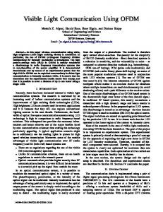
Illustration of the concept of platooning, here with the SARTRE project.
7
1.4
Detail of (a) the DSRC layers [14] and (b) the C-ITS layers [15]. . . .
9
1.5
Different characteristics of lidar, radar, ultrasonic and passive visual (camera) sensors [18]. . . . . . . . . . . . . . . . . . . . . . . . . . . .
1.6
10
Range-finding and data transmission requirements for highway platooning applications. . . . . . . . . . . . . . . . . . . . . . . . . . . . .
12
2.1
Optical beacons used in VICS [21]. . . . . . . . . . . . . . . . . . . . .
17
2.2
Evolution over the years of the number of academic publications referenced by the IEEE Xplore Digital Library when searching the term ‘Visible Light Communication’. . . . . . . . . . . . . . . . . . . . . . .
19
2.3
General architecture of a VLC system. . . . . . . . . . . . . . . . . . .
19
2.4
(a) Package of a ‘Superflux’ red LED commonly used for automotive back lighting and (b) corresponding transmission beam pattern [30]. .
2.5
20
Relative spectral sensitivity of a photodiode against (a) the wavelengths and (b) the angular displacement [31]. . . . . . . . . . . . . . .
21
2.6
The different VLC link configurations [23]. . . . . . . . . . . . . . . . .
22
2.7
Block diagram of the I2V-VLC (a) emitter and (b) receiver proposed by Hochstein in [38]. . . . . . . . . . . . . . . . . . . . . . . . . . . . .
2.8 2.9
26
Illustration of the camera optical channel behavior with images of the traffic light captured (a) at short distance and (b) at log distance [48].
27
User interface of the camera-based V2V-VLC system detailed in [63]. .
30
2.10 Transimpedance amplifier stage with (a) an ideal photodiode and (b) the equivalent model of a real photodiode. . . . . . . . . . . . . . . . .
31
2.11 Detailed design of the VLC receiver used in [68]. . . . . . . . . . . . .
33
2.12 Detailed view of the OCI sensor [63]. . . . . . . . . . . . . . . . . . . .
35
2.13 Block diagram of the VLC prototype for scooter-to-scooter communication [80]. . . . . . . . . . . . . . . . . . . . . . . . . . . . . . . . . .
36
2.14 General design of the VLC function of the VLCR. . . . . . . . . . . .
38
2.15 Basic design of an LED headlamp [89]. . . . . . . . . . . . . . . . . . .
41
x 2.16 (a) Current-voltage characteristics of the headlamps used in the prototypes and (b) evolution of their maximum luminous intensity with the forward current. . . . . . . . . . . . . . . . . . . . . . . . . . . . .
41
2.17 Spatial distribution of the luminous intensity of a headlamp driven by a current of 600 mA, when projected on a vertical plane at 4.5 m. The point of origin is the point of maximum luminous intensity 50 L. . . .
42
2.18 Frequency responses of both headlamps with the -3 dB limit. . . . . .
42
2.19 Current-voltage characteristic of the COTS taillights when (a) in stop mode and (c) in traffic mode, evolution of their maximum luminous intensity with the forward voltage when (b) in stop mode and (d) in traffic mode. . . . . . . . . . . . . . . . . . . . . . . . . . . . . . . . . .
43
2.20 Spatial distribution of the luminous intensity of a taillight when projected on a vertical plane at 1 m in (a) traffic mode and (b) stop mode. 44 2.21 Frequency responses of the taillights in traffic mode (plain blue line) and stop mode (dashed red curve), with the -3 dB limit (yellow dashed dots). . . . . . . . . . . . . . . . . . . . . . . . . . . . . . . . . . . . .
45
2.22 LiFi modulation techniques tree [91]. . . . . . . . . . . . . . . . . . . .
46
2.23 Frequency spectrum of an OOK data signal at fc = 2 MHz, with (a) no additional coding and (b) Manchester coding. . . . . . . . . . . . .
47
2.24 Modulation of the data frame 01101100 in OOK, PAM-4 and GSSK with Manchester coding according to the clock signal of rate fc . . . . .
49
2.25 Block diagram of the boomerang system [110]. . . . . . . . . . . . . .
51
2.26 Illustration of the concept of (a) passive reflection and (b) active reflection. . . . . . . . . . . . . . . . . . . . . . . . . . . . . . . . . . . . 3.1
52
Working principles of triangulation, with α, β and Φ the angles of emission, δ, γ and ψ the angles of incidence and d the distance between the emitter and the receiver [126]. . . . . . . . . . . . . . . . . . . . .
3.2
Geometrical principles of the automotive triangulation rangefinder proposed in [127].
3.3
57
. . . . . . . . . . . . . . . . . . . . . . . . . . . . . . .
57
Principles of the positioning rangefinder based on the automotive lighting proposed in [128], with τi the propagation delays from both emitters, separated by a distance LA , to both receivers, separated by a distance LB . . . . . . . . . . . . . . . . . . . . . . . . . . . . . . . . . .
3.4
58
Principles of FMCW range-finding. The signal sent Er is modulated with a linear frequency modulation of depth ∆f and the echo received Em contains a frequency shift fif proportional to the distance d. . . .
3.5 3.6
59
Different types of automotive radars with their respective characteristics [130]. . . . . . . . . . . . . . . . . . . . . . . . . . . . . . . . . . .
60
General design of the FMCW radar proposed in [130]. . . . . . . . . .
61
xi 3.7
Principles of pulsed TOF distance measurement with light. A signal E(t) is sent and the echo, reflected by a target at distance D, is received with a proportional delay ∆t [138]. . . . . . . . . . . . . . . . . . . . .
62
3.8
Working principles of a TOF 3D camera rangefinder [140]. . . . . . . .
64
3.9
Design of the automotive laser phase-shift rangefinder proposed in [145]. 66
3.10 (a) Block diagram of the auto-digital phase measurement technique and (b) chronogram illustrating its functioning. . . . . . . . . . . . . .
69
3.11 Heterodyning of a signal se by undersampling with a synchronized clock sh when r = 10. . . . . . . . . . . . . . . . . . . . . . . . . . . .
70
3.12 Block diagram of the VLCR. . . . . . . . . . . . . . . . . . . . . . . .
72
3.13 Block diagram of the VLR. . . . . . . . . . . . . . . . . . . . . . . . .
74
3.14 Set-up of the general positioning VLCR, with dx , φx and ψx denoting the different distances, irradiance angles and incidence angles. . . . . .
75
3.15 Set-up of the straight line positioning VLCR, with dx , φx and ψx denoting the different distances, irradiance angles and incidence angles. .
76
3.16 Evolution of the count-induced distance error with the counting frequency fclock and the intermediate frequency fi , whatever the heterodyning method used. . . . . . . . . . . . . . . . . . . . . . . . . . . . .
78
3.17 Heterodyning of a signal sr by undersampling with a non-synchronized clock sh when r = 10. . . . . . . . . . . . . . . . . . . . . . . . . . . .
79
3.18 Illustration of the production of two phase-shift pulses with an heterodyning of factor r = 10. . . . . . . . . . . . . . . . . . . . . . . . . . .
80
3.19 Geometry of a platoon in a straight line configuration. . . . . . . . . .
81
3.20 Evolution of (a) the maximum static error δdm,het induced by the heterodyning step and (b) the intermediate frequency fi with the heterodyning factor r and the frequency of operation fe . . . . . . . . . . . . 4.1
83
Geometry used for the channel gain derivation, with θ and φ the polar and azimuth angles of emission, ψ the angle of incidence, Ar the PD area, Aef f the effective PD area seen from the transmitter and d the distance from the transmitter to the receiver. . . . . . . . . . . . . . .
4.2
88
Two-vehicles platoon of inter-distance d, in a curve of center C and radius R and fully defined by the angle α. . . . . . . . . . . . . . . . .
92
4.3
Simulink model of the VLR. . . . . . . . . . . . . . . . . . . . . . . . .
93
4.4
Details on the signal reconstruction blocks ‘Rx LV’ and ‘Rx FV’ of the VLR. . . . . . . . . . . . . . . . . . . . . . . . . . . . . . . . . . . . . .
4.5
94
Evolution with the distance of the SNR at the receiver level and in the reference axis of the transmitter when the latter is a headlamp (plain blue line) or a taillight (red dashes). . . . . . . . . . . . . . . . . . . .
95
xii 4.6
(a) Square signal se transmitted at 1 MHz, (b) signal sp0 produced by the front-end stage of the receiver with an SNR = 3 dB, before processing and (c) after filtering with 4th order Butterworth filters of respective low-pass cut-off frequency 1.05 MHz and high-pass cut-off frequency 950 kHz, (d) square signal sr0 reconstructed by zero-crossing detection. . . . . . . . . . . . . . . . . . . . . . . . . . . . . . . . . . .
4.7
96
Evolution with the SNR of the similarity between the transmitted and reconstructed square signals se and sr0 for different orders of the reconstruction filters. . . . . . . . . . . . . . . . . . . . . . . . . . . . . .
4.8
97
Evolution of the distance measured by an ideal VLR when operating at fe = 1 MHz with an heterodyning factor r = 3999 over a range going from 5 m to 150 m by steps of 1 m. . . . . . . . . . . . . . . . . 100
4.9
Evolution of the distance measured by an ideal VLR for various heterodyning factors r and frequencies of operation fe . . . . . . . . . . . . 101
4.10 Evolution with the real distance, in the central case (‘Case 1’) and by steps if 1 cm, of the distance measured by the VLR (blue line) with its linear fit (red dashes) and of the real distance (black dots). . . . . . . 102 4.11 Evolution, by steps of 1 cm, of the distance measurement error against the real distance before correction for the central case (‘Case 1’). . . . 103 4.12 Histogram of the distance measurement error after correction over the range going from 5 m to 30 m (blue blocks) and its Gaussian fit (red curve) in the central case (‘Case 1’). . . . . . . . . . . . . . . . . . . . 103 4.13 (a) Part of the signal sp produced by the PD of the FV while the V2V distance is 50 m, (b) signal obtained after band-pass filtering and (c) signal reconstructed sr . . . . . . . . . . . . . . . . . . . . . . . . . . . 104 4.14 Evolution, by steps if 1 cm, of the distance measured by the VLR against the real distance for different orders of filters (a) before correction and (b) after correction over then range going from 5 m to 30 m. . . . . . . . . . . . . . . . . . . . . . . . . . . . . . . . . . . . . . . 107 4.15 Evolution, by steps if 1 cm, of the distance measured against the real distance with various heterodyning factors r. . . . . . . . . . . . . . . 108 4.16 Evolution, by steps if 1 cm, of the distance measured against the real distance with various frequencies of operation fe . . . . . . . . . . . . . 110 4.17 Histogram of the distance measurement error after correction (blue blocks) and its Gaussian fit (red curve) in the case of a frequency of operation fe = 4 MHz (‘Case 5’). . . . . . . . . . . . . . . . . . . . . . 110 4.18 (a) Time evolution of the distance measured by the VLR (blue line) and of the actual distance (red dashes) while the FV is moving toward the LV at v0 = 20 km/h from an initial distance of 15 m and (b) histogram of the resulting measurement error (blue blocks) with its Gaussian fit (red line). . . . . . . . . . . . . . . . . . . . . . . . . . . . 112
xiii 4.19 Evolution, by steps of 1 cm, of the lateral and longitudinal coordinates xFVL and yFVL of the point FVL estimated by the VLR and of their true values. . . . . . . . . . . . . . . . . . . . . . . . . . . . . . . . . . 114 4.20 Histogram of the error (blue blocks) in (a) longitudinal coordinate xFVL and (b) the lateral coordinate yFVL with its Gaussian fit (red curve). . 115 4.21 Block diagram of the Simulink model for the VLCR. . . . . . . . . . . 117 4.22 (a) Data signal transmitted me0 , (b) signal received mp with AWGN of SNR = 3 dB, before processing and (c) after filtering with two 2nd order Butterworth filters of respectively low-pass cut-off frequency 500 kHz and high-pass cut-off frequency 5 kHz (blue curve) and hysteresis triggering (dotted and plain red lines), (d) signal dr reconstructed by triggering. . . . . . . . . . . . . . . . . . . . . . . . . . . . . . . . . . . 119 4.23 Cross-correlation between a transmitted binary message and its reconstructed version after ‘VLC filtering’. . . . . . . . . . . . . . . . . . . . 120 4.24 (a) Data signal transmitted me0 , (b) signal received mp with AWGN of SNR = 3 dB, before processing and (c) after filtering with two 2nd order Butterworth filters of respectively low-pass cut-off frequency 2.5 MHz and high-pass cut-off frequency 250 kHz (blue curve) and hysteresis triggering (dashed and plain red lines), (d) signal dr reconstructed by triggering. . . . . . . . . . . . . . . . . . . . . . . . . . . . . . . . . 121 4.25 Cross-correlation between a transmitted binary message and its reconstructed version after (a) ‘VLC filtering’ and (b) ‘VLR filtering’. . . . 122 4.26 BER and PER evolution against the inter-vehicle distance by steps of 50 cm and combination of ‘VLC filtering’ (VLCf ) or ‘VLR filtering’ (VLRf ) with pulse width decoding (PWd ) or clock decoding (Cd ). . . 124 4.27 (a) Signal mp0 received by the LV from a distance of 40 m, (b) signal filtered by ‘VLR filtering’ and (c) signal reconstructed dr0 . . . . . . . . 124 4.28 Distribution of the pulse width count values when the V2V distance is (a) 25 m and (b) 75 m. . . . . . . . . . . . . . . . . . . . . . . . . . . . 126 4.29 (a) Evolution, against the real distance (black dotted line), of the estimated distance using ‘VLR filtering’ (red dashes) and ‘VLC filtering’ (blue curve), (b) histogram of the error after correction over the range 1 m to 30 m in the case of ‘VLR filtering’ with its Gaussian fit curve.
127
5.1
Typical MOSFET driver for LED. . . . . . . . . . . . . . . . . . . . . 133
5.2
Light signals, observed with a Thorlabs PDA8A, produced by the headlamps and taillights when driven by a square wave of frequency (a) 100 kHz and (b) 1 MHz. . . . . . . . . . . . . . . . . . . . . . . . . . . . . 134
5.3
Frequency response of the custom-made front-end (blue line) with the -3 dB limit (red dashes). . . . . . . . . . . . . . . . . . . . . . . . . . . 136
5.4
Block diagram of the processing chain used for VLC signal reception and reconstruction. . . . . . . . . . . . . . . . . . . . . . . . . . . . . . 136
xiv 5.5
Time evolution of a data signal 100110 transmitted from 10 m at 100 kbps with a single taillight in traffic mode after (a) reception by the front-end stage, (b) band-pass filtering of low-pass and high-pass cutoff frequencies of respectively 100 kHz and 1 kHz, (c) amplification and (d) zero-crossing detection. . . . . . . . . . . . . . . . . . . . . . . . . 137
5.6
Distribution of the count values obtained with pulse width decoding in the offline mode, with a sampling rate equal to 12.5fc , on packets started by the header H = 1111. . . . . . . . . . . . . . . . . . . . . . 139
5.7
Emitter and receiver structures used for the VLC experiments. . . . . 139
5.8
OOK data signal at 100 kbps digitized in the case of F2L communication at 30 m. . . . . . . . . . . . . . . . . . . . . . . . . . . . . . . . . 141
5.9
(a) OOK data signal at 100 kbps digitized in the case of L2F communication with taillights in traffic mode at 10 m, (b) histogram of the pulse width values when d = 12 m. . . . . . . . . . . . . . . . . . . . . 142
5.10 Example of transmission latency at 100 kbps, measured as the time between the first rising edge of the message (in orange) and the rising edge of the enable bit (in blue). . . . . . . . . . . . . . . . . . . . . . . 144 5.11 Set-up used to investigate the impact of the interferences generated by other vehicles, in both the F2L vehicle communication and L2F vehicle communications cases. . . . . . . . . . . . . . . . . . . . . . . . . . . . 145 5.12 Evolution with the longitudinal distance of the contribution of the jamming light signal in the total illuminance perceived at the receiver level when the lateral distance is 2 m. . . . . . . . . . . . . . . . . . . 146 5.13 Block diagram of the VLC system operating at 100 kbps used in dynamic tests [172]. . . . . . . . . . . . . . . . . . . . . . . . . . . . . . . 148 5.14 Optical system placed in front of the Thorlabs PDA100A to enhance the optical power received [172].
. . . . . . . . . . . . . . . . . . . . . 149
5.15 General view of the set-up used for the tests in real driving conditions [172]. . . . . . . . . . . . . . . . . . . . . . . . . . . . . . . . . . . . . . 150 5.16 (a) 18 km freeway segment along which the vehicles have been driven and (b) view of the V2V configuration provided by the Mio Combo 5107 [172]. . . . . . . . . . . . . . . . . . . . . . . . . . . . . . . . . . . 151 5.17 Time evolution of the BER, calculated every 10000 consecutive bits (black peaks), and of the longitudinal V2V distance (orange curve).
. 152
5.18 Spatial distribution of the PRR at 100 kbps. The point of origin is the location of the FV whereas the points on the grid are the different positions of the LV. . . . . . . . . . . . . . . . . . . . . . . . . . . . . . 152 5.19 Examples of PAM-4 data signal at 200 kbps detected by one of the receivers when the V2V distance is 30 m, with its decoding zones defined by the black horizontal lines. . . . . . . . . . . . . . . . . . . . . . . . 155
xv 5.20 Left column: GSSK signals at 200 kbps sampled by the left receiver (blue line) and the right receiver (orange dashes) when the V2V distance is (a) 5 m, (b) 10m and (c) 30 m. Right column: Lateral evolution, at the receivers level, of the illuminance produced by the left headlamp (blue dotted dashes), the right headlamp (red dotted plain line) and both headlamps (orange line) when the V2V distance is (d) 5 m, (e) 10 m and (f) 30 m. . . . . . . . . . . . . . . . . . . . . . . . . 156 5.21 Example of GSSK data signals at 200 kbps sampled by the left receiver (blue line) and the right receiver (orange dashes) when the FV/LV distance is d = 10 m and the radius of the curve is R = 100 m. . . . . 158 5.22 Emitter and receiver structures used for the VLC experiments with large clock rates. . . . . . . . . . . . . . . . . . . . . . . . . . . . . . . 159 5.23 Example of (a) OOK data signal with fc = 2 MHz, (b) PAM-4 data signals with fc = 200 kHz (blue line), fc = 500 kHz (red dashes), fc = 1 MHz (yellow dots-dashes) and fc = 2 MHz (purple dots) and (c) GSSK data signals of the left (blue line) and right (red dashed line) receivers, with fc = 2 MHz. In (b), signals are time scaled to ease comparison. . 161 5.24 Comparison of the characteristics of OOK, PAM-4 and GSSK according to their data rate, simplicity of implementation and robustness to mobility, for a BER below 10−6 , in highway platooning configurations. 163 5.25 Illustration of the processing chain of the VLR: in yellow, input signal of peak-to-peak amplitude 20 mVpp and SNR = 5 dB, in purple, its FFT, in pink, signal obtained after band-pass filtering and in blue square signal reconstructed by the high-speed comparator. . . . . . . . 166 5.26 Details of the reconstructed sine wave (in pink) and square wave (in blue) when the input signal (in yellow) is noiseless. . . . . . . . . . . . 166 5.27 Evolution of the average phase-shift measured by the dedicated FPGA algorithm with an heterodyning factors r = 3950.007.
. . . . . . . . . 168
5.28 Distribution of the measurement error induced by FPGA implementation of the auto-digital phase measurement algorithm. . . . . . . . . . 168 5.29 Detail on the evolution of the average phase-shift measured by the dedicated FPGA algorithm with an heterodyning factors r = 3950.007. 169 5.30 Set-up used during the VLR experiments, with at the top the FV and at the bottom the LV. . . . . . . . . . . . . . . . . . . . . . . . . . . . 170 5.31 Evolution of the average distance measured by the VLR against the real distance with the linear fits of its decreasing and increasing sections.171 5.32 (a) Evolution of the distance measured after correction (blue dots) and of the true V2V distance (red dashes), (b) evolution of the mean measurement error after correction. . . . . . . . . . . . . . . . . . . . . 173 5.33 Distribution, before correction, of 4096 consecutive measurements performed at a ‘true’ V2V distance of 18 m (blue blocks) and resulting Gaussian fit (red curve). . . . . . . . . . . . . . . . . . . . . . . . . . . 174
xvi 5.34 (a) Evolution of the distance measured after correction with the corresponding error bars (blue dots) and of the true V2V distance (red dashes), (b) evolution of the mean measurement error with the corresponding error bars after correction. . . . . . . . . . . . . . . . . . . . 175 5.35 Distribution of the phase-shift, expressed as a distance, between a signal se and its version sr directly reconstructed by a processing card when the room temperature is (a) 23◦ C and (b) 26◦ C. . . . . . . . . . 177 5.36 Flow chart of the calibration process of the VLR from the FV point of view. . . . . . . . . . . . . . . . . . . . . . . . . . . . . . . . . . . . . . 178 A.1 Luminosity function V (λ) in the photopic and scotopic domains. . . . 204 A.2 Geometrical configuration of a light source and a photo-receiver. . . . 206 A.3 MATLAB software for photometric and radiometric characterization from LED datasheets. . . . . . . . . . . . . . . . . . . . . . . . . . . . 208 A.4 Luminous intensity distribution required for every headlamps in lowbeam mode by the ECE R112 regulation [87]. . . . . . . . . . . . . . . 210 A.5 Projection of the low-beam luminous intensity distribution required on a road by night. . . . . . . . . . . . . . . . . . . . . . . . . . . . . . . . 210 B.1 Geometry of the platoon studied for the dynamic error derivation. . . 213 B.2 Set-up of the straight line positioning VLR, with dx , φx and ψx denoting the different distances, irradiance angles and incidence angles. . . . 217 B.3 Geometry of the platoon for the derivation of the configuration angle α.218 C.1 Details of (a) the heterodyning clock sh , (b) the signal sr reconstructed by the FV and (c) the heterodyned version srh of sr . . . . . . . . . . . 221 C.2 Time variations of srh while the rising edges of sr and sh are close with r = 3999. . . . . . . . . . . . . . . . . . . . . . . . . . . . . . . . . . . 222 C.3 Time variations of srh while the rising edges of sr and sh are close with r = 1599. . . . . . . . . . . . . . . . . . . . . . . . . . . . . . . . . . . 223 C.4 Histogram of the 512 consecutive measures output by our algorithm for a true distance of 6.2457 m. . . . . . . . . . . . . . . . . . . . . . . 224 C.5 Evolution of the probability of occurrence of the different distances output by the VLR for a same true distance. . . . . . . . . . . . . . . 224
xvii
List of Tables 2.1
Comparison of VLC, IR and RF communication technologies, reproduced from [20]. . . . . . . . . . . . . . . . . . . . . . . . . . . . . . . .
24
2.2
Comparison of the performances of PD and camera as VLC receiver. .
36
2.3
Comparison of different studies using PD as VLC receiver (ND is nondefined and NA is non-applicable). . . . . . . . . . . . . . . . . . . . .
39
2.4
OOK modulation with Manchester coding. . . . . . . . . . . . . . . . .
46
2.5
PAM-4 modulation with Manchester coding. . . . . . . . . . . . . . . .
48
2.6
GSSK modulation with Manchester coding. . . . . . . . . . . . . . . .
48
4.1
Summary of the parameters used in the Simulink simulations with their value. . . . . . . . . . . . . . . . . . . . . . . . . . . . . . . . . . . . .
4.2
98
Evolution of the distance measurement resolution with the range of correction in the central case (‘Case 1’). . . . . . . . . . . . . . . . . . 105
4.3
Different settings tested for the longitudinal performances evaluation of the VLR. . . . . . . . . . . . . . . . . . . . . . . . . . . . . . . . . . 105
4.4
Evolution of the distance measurement resolution with the range of correction and the filtering order. . . . . . . . . . . . . . . . . . . . . . 107
4.5
Summary of the parameters used during the simulations of the VLCR. 123
4.6
Evolution, with the length of the range of correction, of σVLRf , σVLCf and σVLR , the standard deviations of the distance error in the case of, respectively, the VLCR with ‘VLR filtering’ and ‘VLC filtering’, and the VLR alone. . . . . . . . . . . . . . . . . . . . . . . . . . . . . . . . 128
5.1
Summary of the characteristics of the commercial and custom-made front-ends used in the experiments. . . . . . . . . . . . . . . . . . . . . 135
5.2
Summary of the performances of our VLC prototype at 100 kbps in the various configurations tested, for a BER < 10−6 . . . . . . . . . . . 143
5.3
Summary of the performances of our VLC prototype at 100 kbps in jamming configurations, with a receiver FOV of 55◦ . . . . . . . . . . . 146
5.4
Summary of the performances of our VLC prototype in the various configurations tested with the different modulations, for a BER < 10−6 , with d the V2V distance, R the curve radius and NA meaning nonapplicable. The corresponding data rate is 100 kbps with OOK and 200 kbps with PAM-4 and GSSK. . . . . . . . . . . . . . . . . . . . . . 159
xviii 5.5
Comparison between the data transmission requirements for platooning applications and the results obtained during the experiments. . . . 162
5.6
Evolution of the standard deviation of the measurement distribution with the true V2V distance. . . . . . . . . . . . . . . . . . . . . . . . . 172
A.1 Photometric quantities with their units and, on the same line, equivalence in the radiometric domain (lm = lumen, W = watt, cd = candela, sr = steradian, lx = lux, m = meter). . . . . . . . . . . . . . . . . . . 204 A.2 Values of the different tests points and zones [87]. . . . . . . . . . . . . 209 A.3 Illuminance of the sunlight in different conditions [179]. . . . . . . . . 211
xix
List of Abbreviations 2D
Two-Dimensional
3D
Three-Dimensional
ABS
Anti-Lock Braking System
ACC
Adaptive Cruise Control
ADAS
Advanced Driver Assistance System
ADC
Analog-to-Digital Converter
APD
Avalanche Photodiode
AWGN
Additive White Gaussian Noise
BER
Bit Error Rate
BJT
Bipolar Junction Transistor
C-ITS
Cooperative Intelligent Transportation Systems
CAM
Cooperative Awareness Message
CDMA
Code Division Multiple Access
CMOS
Complementary Metal Oxyde Semiconductor
CNIT
Consorzio Nazionale Interuniversitario per le Telecommunicazioni
COTS
Commercial Off-The-Shelf
DC
Direct Current
DD
Direct Detection
DENM
Decentralized Environmental Notification Messages
DEVAC
Distance Estimation Via Asynchronous Clocks
DEVAPS
Distance Estimation via Asynchronous Phase-Shift
DSRC
Dedicated Short-Range Communications
DSSS
Direct Sequence Spread Spectrum
ESC
Electronic Stability Control
EU
European Union
F2L
Following-to-Leading
FCC
Federal Communications Commission
FET
Field-Effect Transistor
FFT
Fast Fourier Transform
FMCW
Frequency Modulated Continuous Wave
FOV
Field-of-View
FPGA
Field-Programmable Gate Array
FSK
Frequency-Shift Keying
FSO
Free Space Optical
FV
Following Vehicle
xx GBWP
Gain-Bandwidth Product
GCDC
Grand Cooperative Driving Challenge
GNSS
Global Navigation Satellite System
GPIO
General Purpose Input/Output
GPS
Global Positioning System
GSSK
Generalized Space Shift Keying
I2V
Infrastructure-to-Vehicle
ICSA
Infrared Communication Systems Association
ICT
Information and Communication Technologies
IEEE
Institute of Electrical and Electronics Engineers
IM
Intensity Modulation
INRIA
Institut National de Recherche en Informatique et en Automatique
IPCC
Intergovernmental Panel on Climate Change
IR
Infrared
IrDA
Infrared Data Association
ITS
Intelligent Transportation Systems
ITU
International Telecommunication Union
JEITA
Japan Electronics and Information Technology Industries Association
JV
Jamming Vehicle
L2F
Leading-to-Following
Laser
light Amplification by Stimulated Emission of Radiation
LED
Light-Emitting Diode
Leddar
Light-Emitting Diode Detection and Ranging
Lidar
Light Detection and Ranging
LiFi
Light Fidelity
LOS
Line-of-Sight
LRR
Long-Range Radar
LTE
Long-Term Evolution
LTI
Linear Time-Invariant
LV
Leading Vehicle
MAC
Medium Access Control
MCM
Multicarrier Modulation
MOSARIM
More Safety for All by Radar Interference Management
MOSFET
Metal Oxide Semiconductor Field-Effect Transistor
MRR
Medium-Range Radar
NA
Non-Applicable
ND
Non-Defined
NIR
Near-Infrared
NLOS
Non-Line-of-Sight
NTU
National Taiwan University
OCC
Optical Camera Communication
OCI
Optical Communication Image
xxi OFDM
Orthogonal Frequency Division Multiplexing
OMEGA
Home Gigabit Access
OOK
On-Off-Keying
OWC
Optical Wireless Communication
PATH
Partners for Advanced Transportation Technology
PAM
Pulse Amplitude Modulation
PD
Photodiode
PER
Packet Error Rate
PHY
Physical Layer
PIN
Positive Intrinsic Negative
PLL
Phase-Locked Loop
PN
Pseudo-Random Noise
PPM
Pulse Position Modulation
PRR
Packet Reception Rate
PWM
Pulse Width Modulation
QAM
Quadrature Amplitude Modulation
QPSK
Quadrature Phase-Shift Keying
Radar
Radio Detection and Ranging
RF
Radio Frequency
RMS
Root Mean Square
SARTRE
Safe Road Trains for the Environment
SCM
Single Carrier Modulation
SNR
Signal-to-Noise Ratio
SPAPD
Single-Photon Avalanche Photodiode
SRR
Short-Range Radar
TG
Task Group
TIA
Transimpedance Amplifier
TOF
Time-Of-Flight
UFSOOK
Undersampled Frequency Shift On-Off Keying
USDOT
United States Department of Transportation
USRP
Universal Software Radio Peripheral
UWB
Ultra-Wide Band
V2V
Vehicle-to-Vehicle
VANET
Vehicular Ad-Hoc Network
VICS
Vehicle Information and Communication System
VLC
Visible Light Communication
VLCA
Visible Light Communication Association
VLCC
Visible Light Communication Consortium
VLCR
Visible Light Communication Rangefinder
VLR
Visible Light Rangefinder
WAVE
Wireless Access in Vehicular Environments
WLAN
Wireless Local Area Network
xxii WiFi
Wireless Fidelity
WiMAX
Worldwide Interoperability for Microwave Access
XOR
Exclusive Or
xxiii
List of Symbols and Notations Ar
Photodiode sensitive area
m2
B
Receiver bandwidth
Hz
2.99792458×10⁸ )
m·s−1
c
Speed of light (=
d
Vehicle-to-vehicle absolute distance
m
dm
Vehicle-to-vehicle absolute distance estimated
m
df v
Raw data sent by the following vehicle
no units
dlv
Raw data sent by the leading vehicle
no units
fc
Clock rate
Hz
fclock
Frequency of the counter clock
Hz
fe
Frequency of emission
Hz
fh
Heterodyning frequency
Hz
fHP
High-pass 3 dB cut-off frequency
Hz
fi
Intermediate frequency
Hz
fLP
Low-pass 3 dB cut-off frequency
Hz
G
Open loop voltage gain
no units
gm
FET transconductance
S
H
Packet header
no units
I2
Noise-bandwidth factor
no units
I3
Noise-bandwidth factor
no units
Ibg
Background photocurrent 1.38×10⁻²³ )
A J·K−1
k
Boltzmann constant (=
`
Distance between both headlamps or taillights
m
m
Lambertian order of the light source
no units
M
Number of clock ticks
no units
me
Data signal sent by the following vehicle
no units
me0
Data signal sent by the leading vehicle
no units
mp
Data signal received by the following vehicle
no units
mp0
Data signal received by the leading vehicle
no units
mr
Data signal reconstructed by the following vehicle
no units
mr0
Data signal reconstructed by the leading vehicle
no units
N
Averaging factor
no units
Pt
Optical power transmitted
W
Pr
Average optical power received
W
q
Electronic charge (=
1.6×10⁻¹⁹ )
C
xxiv r
Heterodyning factor
no units
R
Curve radius
m
Rb
Data bit rate
bits·s−1
sclock
Counter clock
no units
se
Clock transmitted by the following vehicle
no units
seh
Heterodyned version of the clock transmitted
no units
sh
Heterodyning clock
no units
sr
Clock recovered by the following vehicle
no units
sr 0
Clock recovered by the leading vehicle
no units
srh
Heterodyned version of the clock received
no units
TK
Absolute temperature
K
α
Configuration angle
rad
γ
Photodiode responsivity
A·W−1
Γ
FET channel noise factor
no units
η
Capacitance of photo-detector per unit era
F·m−2
θ
Polar angle of emission
rad
λ
Wavelength of the light signal
m
σ
Standard deviation of the measurement error
m
φ
Azimuth angle of emission, or irradiance angle
rad
ϕ
Phase-shift
rad
ϕm
Phase-shift estimated
rad
Φ1/2
Semi-angle at half power
rad
ψ
Incidence angle
rad
Ψc
Photodiode field-of-view
rad
1
Chapter 1
The Road Toward Full Vehicle Automation Contents 1.1
1.2
1.3
1.1 1.1.1
Why the Autonomous Vehicle? . . . . . . . . . . . . . . . .
1
1.1.1
The Transportation Challenges . . . . . . . . . . . . . . . .
1
1.1.2
Core Functions of the Autonomous Vehicle . . . . . . . . .
3
A Progressive Automation . . . . . . . . . . . . . . . . . . .
4
1.2.1
The Different Steps of Automation . . . . . . . . . . . . . .
4
1.2.2
Platooning . . . . . . . . . . . . . . . . . . . . . . . . . . .
5
1.2.3
Communication and Range-Finding Technologies in ITS . .
8
Objectives and Outline of the Thesis . . . . . . . . . . . . .
11
1.3.1
Objectives of This Work . . . . . . . . . . . . . . . . . . . .
11
1.3.2
Report Outline . . . . . . . . . . . . . . . . . . . . . . . . .
12
Why the Autonomous Vehicle? The Transportation Challenges
Over the past few decades, most countries around the world have experienced a growing demand in mobility and especially in individual mobility. So far, this demand has been filled by individual cars which have become in a century a central part of everyday life. Figure 1.1(a) shows the rapid growth of the vehicle fleet in the Europe Union (EU) between 1992 and 2014 whereas Figure 1.1(b) details the passenger and goods transport growth, also in the EU, between 1995 and 2013. This rapid growth has obviously its downside. The number of road fatalities has continuously grown over the past decades and has only started to stabilize in 2013, with around 1.25 million deaths per year and an additional 20 to 50 million people injured, especially in the poorest countries. Half of these deaths concern vulnerable
2
Chapter 1. The Road Toward Full Vehicle Automation
road users, that is to say pedestrians, cyclists and motorcyclists [1]. Several studies show that this growth is closely related to the inability of drivers to make the right decision on time. In a report published in 2010, the United States Department of Transportation (USDOT) considered that 81% of the light-vehicle crashes could be prevented by using vehicle-to-vehicle (V2V) and infrastructure-to-vehicle (I2V) communication [2]. Vehicle automation is thus first seen as a solution to reduce the number of road fatalities and injuries.
Figure 1.1: (a) Growth of the vehicle fleet in EU 17 in millions of units [3], (b) passenger and goods transport growth in EU 28 [4].
Traffic growth has also induced a huge increase in greenhouse gas emissions, responsible for climate change. According to the Intergovernmental Panel on Climate Change (IPCC), the transportation field was, in 2010, responsible for 14% of global greenhouse gas emissions, among which road traffic accounted for 70%. These emissions rose 150% between 1970 and 2010 to reach 7.0 Gt equivalent CO2 and are expected to keep growing in the next years [5]. In parallel, traffic growth is leading to higher traffic congestion, especially in large cities, and is thus resulting in higher local air pollution, not to mention the additional noise disturbances and time wasting. One of the answers to these environmental and societal issues is the development of a lowcarbon and intelligent vehicle integrated in a set of intelligent transportation systems
1.1. Why the Autonomous Vehicle?
3
(ITS) that allow better traffic management. Consequently, vehicle automation is pursued in order to ensure safer, more efficient and eco-friendly transportation in a context of growing mobility demand. Note also that the autonomous vehicle will turn the driver into a passenger and thus release the driving time for any other purpose. Last but not least, autonomous vehicles will give a wider access to mobility to the people usually unable to drive.
1.1.2
Core Functions of the Autonomous Vehicle
By definition, an autonomous vehicle must be able to reach a known destination without any action from any passenger. Consequently, such a vehicle must be able to navigate autonomously on a varying environment. According to the scale of the environment we consider, different core functions of the autonomous vehicle can be highlighted. If we consider first the direct environment of the vehicle, then the vehicle must be able, at any moment, to detect, identify and track all the surrounding obstacles, whether they are fixed or moving. Now, if we consider the larger scale covering the current position and the destination of the vehicle, then this vehicle must be aware of the traffic status on the different roads it could take to reach its destination and then must decide which path is the best. Finally, given this local and global environment information, the vehicle must control its trajectory to effectively drive to its final point. We can thus conclude there are at least four vital functions to any autonomous vehicle [6]: • Perception: This is basically the sight of the autonomous vehicle, that is the function allowing to detect and track all the surrounding obstacles and understand their movements. • Communication: V2V and I2V communications allow the autonomous vehicles to receive traffic information from the surrounding roads while sending information about the road they are using. This information is then used by the various vehicles to adjust their path but also by the traffic management centers to supervise the traffic flow and thus mitigate congestion. In addition, communication can complement the perception function for safety purpose. For example, in case of emergency braking, the situation might be understood by the surrounding vehicles faster if a message is directly sent rather than by using sensors. In addition to these security applications, communication can simply be used for infotainment by providing, for example, an on-board Internet access. • Navigation: This function refers to the ability of the autonomous vehicle to plan and optimize its path toward a given destination. Navigation thus requires localization on a dynamically varying environment to avoid local obstacles, but also on a global map to situate the current position and the destination and
4
Chapter 1. The Road Toward Full Vehicle Automation then find the best route. The navigation function is consequently a central organ of the autonomous vehicle that is continuously making decisions. • Control: The control function is finally the function that turns the decisions taken by the navigation function into actions.
1.2 1.2.1
A Progressive Automation The Different Steps of Automation
Even though the technological feasibility of fully autonomous vehicles has already been demonstrated, their massive deployment is very unlikely in the very near future. We should instead experience a growing automation of the different vehicle functions for a growing number of applications. This trend, started in the 1980s, consists in implementing advanced driver assistance systems (ADAS) on the vehicles as a support to the drivers. Figure 1.2 gives a quick chronological overview and the possible future of ADAS evolution [7].
Figure 1.2: Past and potential future evolution toward automated cooperative driving [7].
The first generation of ADAS was dedicated to vehicle dynamics stabilization and was based on sensors monitoring different parameters of the vehicle, also called proprioceptive sensors. One of the first ADAS, serially produced by Bosch from 1978, was the anti-lock braking system (ABS). However, the greatest achievement of this first generation is probably the introduction in 1995 of electronic stability control (ESC) systems that provide much better road-holding.
1.2. A Progressive Automation
5
The second generation of ADAS, which started in the 1990s, is dedicated to information, warning and comfort of the driver. It is based on exteroceptive sensors able to acquire information from the outside of the vehicle. This generation started with on-board navigation systems based on global navigation satellite system (GNSS) receivers, among which the famous global positioning system (GPS). GNSS allows the driver to dedicate most of his mental resources to the driving task and thus helps reduce accidents due to inattention while also reducing fuel consumption by planning optimal routes. In the meantime, in 1991, Mercedes was launching its S-Class W140 equipped with an ultrasonic park assist radar. Ultrasonic sensors have then been complemented with cameras allowing the driver to see the actual obstacles announced by the radars and even a projection of the trajectory according to the actual steering angle. The concept is then extended by Valeo, first with a camera-based system providing to the driver a 360◦ view of the vehicle1 , and then with a system allowing the vehicle to park itself2 . In 2013, Volvo even presented a vehicle able to find a parking slot, park and then leave the slot to pick the driver at a chosen point3 . Another milestone was set in 1999, when Mercedes launched an S-Class embedding an adaptive cruise control (ACC) system which detects the distance to the preceding vehicle and adapts the speed of the vehicle to respect safety distances. Although very expensive at the beginning, this technology based on radio detection and ranging (radar) or even light detection and ranging (lidar) is now much more affordable and allows partially autonomous driving. Finally, we entered around 2010 the third and latest generation of ADAS, dedicated to automated and cooperative driving. These systems are still based on the devices evoked previously – radar, lidar, camera or GNSS – but use in addition new vehicular communication technologies. Consequently, the vehicle does not rely only on data acquired anymore but also on data provided by other vehicles through V2V communication and by road infrastructure through I2V communication. All the data acquired and received are then merged using data fusion strategies in order to combine the strengths of all the sources and thus build a solid and global knowledge of the vehicle situation, which will lead to the optimal decision. Consequently, we are now slowly moving from independent and dedicated ADAS to multi-sensor systems that are opening up a wide range of new industrial possibilities in the automated driving domain [8]. One of these potential applications is platooning.
1.2.2
Platooning
Platooning is, as illustrated by Figure 1.3, a technique that consists in forming a group of vehicles led by a leading vehicle (LV) followed by one or several following vehicles (FV) able to adjust their trajectory autonomously. This trajectory control 1
A demonstration of this system is given here: https://www.youtube.com/watch?v=17nhlpkU86U. A demonstration of this system is given here: https://www.youtube.com/watch?v=ItrfSoSFWf8. 3 A demonstration of this system is given here: https://www.youtube.com/watch?v=GIa1mWr1kNs. 2
6
Chapter 1. The Road Toward Full Vehicle Automation
is done from data provided by on-board sensors as well as V2V communication. The platooning technique provides several advantages. The main benefit is the reduction in traffic congestion it induces. Since the FV are automated, the response time in case of hard braking or acceleration is very short, which means the vehicles can be driven at shorter V2V distances. In addition, by reducing this V2V distance, the FV can benefit from a reduced air drag and thus consume less fuel. Finally, when a vehicle joins a platoon, then its driver is entirely released from the driving task. These promising advantages are particularly interesting to the truck industry since, for example in the EU, the largest portion of freight is transported via road (44%) [9]. Consequently, several research and industrial platooning projects have been carried out over the past few decades. If the first tests on lateral and longitudinal trajectory control date back to the 1960s [10], the first projects really dedicated to platooning started during the 1990s [9], [11]. The California Partners for Advanced Transportation Technology (PATH) program, started in 1986 by the University of California, Berkeley, and still ongoing was the first North American research program to focus on ITS. In 1994, it reports first tests of longitudinal control of a four-vehicle platoon with a V2V distance of 4 m, on a highway. Then, in 1997, PATH develops an eight-vehicle platoon for the National Automated Highway System (NAHS) public demonstrations. These vehicles are able to join and leave a platoon led by an autonomous vehicle at up to 97 km/h. The V2V distance is maintained at 6.5 m within a root mean square (RMS) error of 20 cm whereas the lateral control is based on lane detection. However, the platoons cannot gather light vehicles and trucks at the same time. PATH then focuses on truck platoons and demonstrates the technical feasibility of a three-truck platoon with a V2V distance of 4 m. It also shows that with such truck platoons, the road capacity could be doubled whereas the fuel consumption savings could reach 5% for the LV and 10% to 15% for the FV. From 2005 to 2009, the German national project KONVOI developed a truck platooning system for highways. Each truck is equipped with a full set of ADAS (radar, camera, GPS, ACC. . . ) and wireless local area network (WLAN) V2V communication. Lateral control is here again based lane marking recognition by cameras combined with data from the V2V communication. Consequently, the KONVOI platoon system is developed for highways only. The longitudinal control, on the other hand, is based on an ACC system that ensures a V2V distance of 10 m. The LV is driven by a human driver who also has permanent control of the platoon procedures. The whole system is successfully tested on German highways to form and maintain platoons of three trucks, at speeds between 60 and 80 km/h [9]. Just before the end of the KONVOI project, the EU Commission launched the SAfe Road TRains for the Environment (SARTRE) project, which was completed in 2012 with a particularly advanced platooning system. The platoon, necessarily led by manually driven truck, can include both light vehicles and trucks. Here, the lateral
1.2. A Progressive Automation
7
control does not depend on lane recognition and is thus completely infrastructure independent whereas the longitudinal control is based on common ADAS with additional ITS-G5 V2V communication. Tests carried out on public roads show that platoons of five vehicles with a V2V distance down to 6 m and at a speed up to 90 km/h are possible. This V2V distance is chosen after aerodynamic studies that show the optimal value in terms of fuel consumption is between 6 and 8 m. This first theoretical study is then confirmed by field experiments on a five-vehicle platoon two trucks followed by three cars - moving at 85 km/h. With a V2V gap of 8 m, the fuel consumption is indeed reduced by 12 to 15% for the FV and by 7% for the LV [11], [12]4 .
Figure 1.3: Illustration of the concept of platooning, here with the SARTRE project.
In the meantime, from 2008 to 2013, the Japanese government funded a truck platoon project called Energy ITS. The lateral control is based on lane detection by cameras whereas the longitudinal control uses a combination of ADAS and V2V communication that maintains the V2V distance error at 10 cm. Note, however, that here the V2V communication is implemented using a combination of Dedicated Short-Range Communications (DSRC) and infrared communications transmitting data packets of 50 to 56 bytes with an update period of 20 ms over a range larger than 60 m for DSRC and of 15 m for infrared. Using this configuration, a platoon of three heavy trucks plus an additional light truck is formed and maintained on a private track at 80 km/h with gaps of 10 m and 4.7 m [9], [11]. Finally, the Grand Cooperative Driving Challenge (GCDC) held in 2011 must be mentioned here. This challenge was the first international competition of vehicles connected with communication devices for V2V and I2V communications. Teams from 10 countries developed vehicles that were supposed to form platoons with other vehicles without knowing precisely their algorithms and technical equipment, except some technological prerequisites given by the organizers. For example, the communication protocols had to follow the 802.11p standard developed by the Institute 4
A demonstration video is available at https://www.youtube.com/watch?v=Q4iFuN8orfk.
8
Chapter 1. The Road Toward Full Vehicle Automation
of Electrical and Electronics Engineers (IEEE) and the positioning was necessarily based on high-accuracy real-time kinematic GPS. This challenge, won by the team AnnieWay from the Karlsruhe Institute of Technology, was the occasion to drive the research on vehicle automation [11], [13]. This quick review shows that platooning is indeed a first step for the third generation of ADAS. Several second-generation sensors are combined with vehicular communication in order to collect data that are then fused to provide an optimal control decision. We may thus already find the four vital functions of the autonomous vehicle – perception, communication, navigation and control – even though they are not yet at a full level of development. The communication function is generally implemented using radio frequency (RF) based technologies, with the notable exception of infrared in the Energy ITS project. On the other hand, inter-vehicle distance measurement, which is probably the most vital perception function to platooning systems, is achieved through various sensors such as radar, lidar or even cameras. All these technologies are obviously fully functional but present nevertheless some weaknesses.
1.2.3 1.2.3.1
Communication and Range-Finding Technologies in ITS Communication Systems for ITS and Their Limits
WLAN, DSRC, ITS-G5, IEEE 802.11p. . . These acronyms all stand for RF-based wireless communication technologies used for vehicular communications and more generally for vehicular ad-hoc network (VANET). Although several other radio technologies such as long-term evolution (LTE) or worldwide interoperability for microwave access (WiMAX) can be used, the most prominent technology in VANET remains the vehicle-specific wireless fidelity (WiFi) variation defined by the IEEE 802.11p standard. In the United States, the IEEE 802.11p is integrated in the IEEE 1609 wireless access in vehicular environments (WAVE) protocol stack to form the cornerstone of DSRC systems, especially designed for VANET and operating in the 5.9 GHz band [14]. In Europe, IEEE 802.11p is also used, in a WAVE variant called ITS-G5, as a building block of the DSRC equivalent named cooperative intelligent transportation system (C-ITS). The details of DSRC and C-ITS are summed up by Figure 1.4. Among other things, the C-ITS set of standards defines two types of messages that can be sent [15]: cooperative awareness messages (CAM) and decentralized environmental notification messages (DENM). CAM are used to transmit periodically vehicles state information such as speed or position. On the other hand, DENM are event-triggered messages warning of a potential hazard. In platooning, vehicular communication is used for both periodic broadcasting of vehicle status update and hazard warning. Consequently, both CAM and DENM may be sent.
1.2. A Progressive Automation
9
Figure 1.4: Detail of (a) the DSRC layers [14] and (b) the C-ITS layers [15].
However, the random access protocol for medium access control (MAC) defined by IEEE 802.11p may cause excessive delays imposing a larger V2V distance to meet safety requirements [16]. In addition, if for example an emergency occurs, all surrounding vehicles will most probably broadcast safety warning messages which could result in a broadcast storm. This broadcast storm can cause dramatic channel congestion resulting in severe channel performance degradations. More generally, DSRC and C-ITS are very sensitive to channel congestion when there is a large number of vehicles, that is when the traffic is dense. This phenomenon is reinforced by the fact that DSRC and C-ITS are based on a limited bandwidth around 5.9 GHz. Consequently, as the market penetration rate of vehicular communication will increase, the channel congestion and the resulting communication delays will become more and more concerning. In a context of V2V communication for platooning applications, these issues may become fatal. Consequently, other communication technologies could be used for redundancy. This idea was already used in the Energy ITS project, where a 100 kbps infrared link was dedicated to short-range and multi-hop V2V communication. This idea is also proposed in [17], but with a visible light communication (VLC) link. Here, the taillights of each vehicle are used to transmit a specific payload to the vehicle directly behind. As we will see in Chapter 2, VLC has been considered as a potential candidate for V2V communication for a long time. However, its application to platooning configuration is still a wide and open topic which will be at the heart of the work presented in this document.
1.2.3.2
Range-Finding Systems for ITS and Their Limits
As for vehicular communication, there are several technologies dedicated to distance measurement. The most commonly used in ITS are radar, lidar, ultrasonic sensors and cameras. Radar, lidar and ultrasonic sensors are based on the same principle: they send a wave that is reflected back by the target and then process the echo
10
Chapter 1. The Road Toward Full Vehicle Automation
received in order to extract a parameter – a time, a phase-shift or a frequency-shift – that is proportional to the rangefinder/target distance. Camera-based distance measurement is based on a different idea. Cameras are used as passive light sensors that just provide a flow of images on which the depths of the scene can be recovered by using image processing techniques. Although these different techniques will be further detailed in Section 3.1, Figure 1.5 already gives an overview of their different characteristics.
Figure 1.5: Different characteristics of lidar, radar, ultrasonic and passive visual (camera) sensors [18].
As shown by these diagrams, only lidar, radar and camera can be used to measure distance of at least a few meters. However, lidar are still expensive and cameras cannot work in dark conditions. Radar, on its side, is now a rather affordable technology, functional in most weather conditions but it is necessarily based on radio waves. Most automotive radars actually use a dedicated frequency band, either around 24 GHz or 77-81 GHz. This band is in any case limited, which means that interferences might again be a growing concern when the number of vehicles equipped with such devices will increase. Consequently, redundant medium-to-long-range distance measurement sensors might be useful. Since the communication function can already be supported by the automotive lighting through VLC, it could be interesting to use it for rangefinding purpose also.
1.3. Objectives and Outline of the Thesis
1.3
11
Objectives and Outline of the Thesis
1.3.1
Objectives of This Work
As outlined in the previous section, both the communication and distance measurement functions of platooning systems may benefit from some redundancy. Consequently, the main goal of the work presented here is to propose a system able to perform simultaneously both functions using the light produced by commercial off-the-shelf (COTS) headlamps and taillights. This system, as extension of the VLC concept, will be called from now on visible light communication rangefinder (VLCR). If platooning is a very general technology that could be used either in cities or highways, we focus here on the latter use case because it is probably the most mature. In such scenario, the VLCR must, of course, respect some performance requirements to be relevant. From the data transmission point of view, these performances can be copied from the characteristics of the infrared system employed in the Energy ITS project. This system enables the transmission over 15 m and at 100 kbps of 50 bytes packets with an update rate of 50 Hz and a packet receiving rate of 99.92%. These constraints actually fit the recommendations of the Vehicle Safety Communications project carried out by the USDOT. In 2005, this project highlighted 34 safety applications that could be addressed by DSRC, among which is platooning [19]. For each application, communication requirements are given. In the case of platooning, the communication system must ensure one-way or two-way communication, point-to-point and point-tomultipoint communication in a periodic transmission mode with an update rate of 50 Hz and over a range of 100 m. The data to be transmitted are the position, velocity, acceleration, heading and yaw-rate of the vehicle and each resulting packet, of approximate size 400 bits, must be received with a latency of at most 20 ms. Therefore, we can consider that our VLCR must: • Enable point-to-point one-way or two-way communication, • in a periodic transmission mode with an update rate of 50 Hz, • over a range going from 1 m to at least 15 m, ideally up to 30 m (given an optimal inter-distance of 6 to 8 m), • to transmit packets of at least 400 bits, • with a latency under 20 ms, or equivalently with at a minimum data rate of 20 kbps, • and with a negligible error rate, • despite the relative movements of the vehicles forming the highway platoon.
12
Chapter 1. The Road Toward Full Vehicle Automation
From the range-finding point of view, the SARTRE project gives some interesting indication on the performances to expect [12]. Consequently, we will consider that the VLCR must provide distance measurement: • over a range going from 1 m to at least 15 m, ideally up to 30 m (given an optimal inter-distance of 6 to 8 m), • with an error around 10 cm, • and at a refresh rate of at least 50 Hz, • despite, once again, the relative movements of the vehicles forming the highway platoon. These various performances requirements are summed up by Figure 1.6.
Figure 1.6: Range-finding and data transmission requirements for highway platooning applications.
1.3.2
Report Outline
After this introduction chapter, detailing the motivations and goals of our work, this report contains five other chapters. Since the VLCR is an extension of the VLC concept, its design is actually close to the structure of a simple VLC system. Consequently, Chapter 2 first presents the VLC technology with its basic principles, advantages, drawbacks and applications. Then, it focuses on VLC for automotive applications by providing a review of the latest works on the subject. This review details in particular how some design choices, as for example the type of light sensor, impact the final characteristics of the system, and will thus help us define the general structure of the VLC function of the VLCR. After defining this structure, the headlamps and taillights that will be used later for the prototype implementation are fully characterized, which then allows us to complete this first design by selecting the modulations best suited to our application. At this point, our VLCR only supports data transmission. The goal of Chapter 3 is thus to determine how the range-finding function could be added while taking into account the VLC system specificity, like the characteristics of the light sources or the
1.3. Objectives and Outline of the Thesis
13
modulation. Consequently, this chapter first reviews the main distance measurement techniques with their working principles and applications to the automotive field, in order to determine which one could still be functional with data transmission. After selecting the relevant technique, the complete structure of the VLCR is finally presented in two different variations: the first performing only an absolute V2V distance measurement and the other allowing relative positioning between two consecutive vehicles. Then, the range-finding function is isolated and analyzed theoretically to determine the sources of errors and their impact on the measurement resolution. The final goal remains, however, to have a quantitative performance evaluation of the system. The first step toward this goal is to determine precisely the design of each one of its building blocks and optimize their respective settings. This process is carried out through computer simulations that are detailed in Chapter 4. These simulations are obviously based on a specific model of the system, but also of the outdoor environment. The light signals produced by the light sources will indeed suffer from several distortions between their emission and reception. These distortions, gathered in the V2V channel, are first presented and modeled mathematically. Then, the model of the system itself is detailed and the results of the simulations are exposed. In order to understand how the distance measurement function behaves, it is first isolated by removing the communication function and simulated in both variations. The results obtained allow us to optimize several settings, especially for the signal reconstruction process. Then, the data transmission part is added and the whole VLCR is simulated to evaluate, on the one hand, the communication performances and, on the other hand, how each function impacts the other. If these simulations give precious indications about the design and validate at the same time the general concept of VLCR, they cannot replace real experiments. In Chapter 5, the practical implementation of the system is presented. The various core bricks are first built and validated. Then the VLC function is assembled and tested in various static configurations typical to platooning scenario in order to check the compatibility of the system with the requirements listed in Section 1.3.1. The different modulations selected in Chapter 2 are also compared and pushed to their limits in order to determine the maximum data rate achievable while maintaining the same quality of service. These first static experiments are completed with outdoor tests in real driving conditions. Note, however, that these tests have been carried out during a research residency at the Mobile and Vehicular Network Laboratory of the National Taiwan University (NTU), and are thus based on the VLC prototype developed by this lab. Similarly, the range-finding function is assembled and tested in order to evaluate the distance measurement performances. Finally, Chapter 6 sums up the work detailed throughout this thesis and lists its main contributions, before giving some concluding remarks on the improvements that could be made on the VLCR and, more generally, on the challenges automotive VLC still has to face.
15
Chapter 2
Visible Light Communication for Automotive Applications Contents 2.1
2.2
2.3
2.4
What Is Visible Light Communication? . . . . . . . . . . .
16
2.1.1
Brief Historical Overview of VLC . . . . . . . . . . . . . . .
16
2.1.2
Basic Principles of VLC . . . . . . . . . . . . . . . . . . . .
19
2.1.3
Advantages, Drawbacks and Applications . . . . . . . . . .
21
Review on Vehicular Visible Light Communication . . . .
25
2.2.1
Early Works
. . . . . . . . . . . . . . . . . . . . . . . . . .
25
2.2.2
Camera as Receiver . . . . . . . . . . . . . . . . . . . . . .
27
2.2.3
Photodiode as Receiver . . . . . . . . . . . . . . . . . . . .
30
2.2.4
Photodiode or Camera? . . . . . . . . . . . . . . . . . . . .
36
General Design of Our System . . . . . . . . . . . . . . . .
37
2.3.1
Overview of the System Structure . . . . . . . . . . . . . .
38
2.3.2
Headlamps and Taillights Characterization . . . . . . . . .
40
2.3.3
Modulations for Automotive VLC . . . . . . . . . . . . . .
45
2.3.4
Adding a Range-Finding Function to the VLC System . . .
50
Conclusions . . . . . . . . . . . . . . . . . . . . . . . . . . . .
53
The first step to take in order to build a VLCR that meets the requirements listed in Section 1.3.1 is obviously to define its general design. The goal of this chapter is to provide a first base on which this design can be built. Since the VLCR is the combination of a communication and a range-finding function, the approach followed here consists in adding one of the functions to a system already performing the other. If automotive lighting has never been used for range-finding purpose so far, many studies have, over the past few years, proposed to use it as data transmitter in VLC systems. As explained in Section 2.1, VLC is a recent wireless communication technology that has met a growing interest since the mid 1990s and presents several advantages but also drawbacks. If its main application field remains indoor communication, the research on automotive applications has made significant progress lately,
16
Chapter 2. Visible Light Communication for Automotive Applications
as detailed in Section 2.2. Using this literature review, a general structure of the VLC function of the VLCR is then presented in Section 2.3. This section also exposes the characterization of the headlamps and taillights on which will be based the system prototypes, as well as the modulations that could be used. It is concluded by a quick literature review of the works proposing simultaneous light-based data transmission and range-finding systems, before moving to Chapter 3 where our own solution will be finally detailed.
2.1
What Is Visible Light Communication?
VLC is an optical wireless communication (OWC) technology where the signal produced by light-emitting diode (LED) emitting in the visible light spectrum is used as data carrier. Although quite recent in terms of applications, VLC is actually the descendant of other OWC technologies. After explaining this filiation quickly in Section 2.1.1, Section 2.1.2 details the basic principles of VLC and introduces in particular two vital components to any VLC system: the LED and the light sensor. Finally, Section 2.1.3 concludes this section by listing the advantages, drawbacks and potential applications of VLC.
2.1.1
Brief Historical Overview of VLC
The wireless transmission of information by light is not new. Beacon fires or smoke signals have been widely used by several cultures whereas from the 18th century, optical telegraphs based on semaphores and distributed all over the territory were used to convey information quickly. For example, in 1792, Claude Chappe and his brothers established a first semaphore line between Paris and Lille composed of fifteen relays, each one being able to transmit 196 different symbols. A message composed of 36 symbols was reaching, at that time, Lille from Paris in around 30 minutes. The heliograph and the signal lamps are other famous examples of early OWC systems. They used specific codes, usually the Morse code invented in 1836, emitted either by a lamp in the case of signal lamps, or by obstructing a sunlight beam generated and directed by mirrors in the case of heliographs. A first fundamental step in OWC was then taken in 1880, when Alexander Graham Bell invented the photophone. By using a vibrating mirror at the transmitter and crystalline selenium cells combined with a parabolic receiver, Bell successfully modulated and transmitted a voice signal through light over 200 m [20]. However, the first major evolution in OWC came in the 1960s, after the invention of light amplification by stimulated emission of radiation (laser) systems able to produce narrow and high-intensity light beams. This invention opened the way for outdoor long-range point-to-point communication systems, generally referred as free space optical (FSO) communication systems and based on infrared (IR) or near-infrared
2.1. What Is Visible Light Communication?
17
(NIR) light. For example, in 1963, a research team in the United States transmitted a voice signal modulated by a laser over 190 km in a single hop. From this time onward, FSO communication has met a growing interest, first for military and space applications and more recently for civil communication networks. Although reliability has for a long time limited the deployment of FSO systems, the rapid development of optoelectronic devices in the past two decades has finally boosted their commercialization. It is now common to see full duplex outdoor FSO communication systems operating perfectly in all weather conditions over 2 to 3 km and at more than 1 Gbps [20]. Outdoor IR communication has also been used in Japan by vehicle information and communication systems (VICS) since 1996. VICS, illustrated by Figure 2.1, provides road traffic information directly on the car navigation screen using radio and IR-I2V communication. Nowadays, more than 30000 IR beacons are distributed all over the Japanese road network and provide, at 1 Mbps over a range of 3.5 m each, information about the traffic as far as 30 km ahead and 1 km backwards [21]. In parallel, IR-based OWC has experienced major developments for indoor applications. A crucial cornerstone was laid in 1979, when Gfeller and Bapst presented an IR system able to reach 1 Mbps in an entire office room thanks to diffuse radiation [22]. Several works then improved the performances of these indoor diffuse IR systems and achieved data rates of tens of Mbps [23]. In the meantime, IR OWC has been widely used for indoor short-range point-to-point communication, especially in remote control devices, but also for data transfer. The Infrared Data Association (IrDA), set up in 1993, even developed a whole set of protocols and open standards for IR OWC.
Figure 2.1: Optical beacons used in VICS [21].
OWC history has thus been dominated for a long time by IR communication. Although visible light lasers and LED were available, IR was preferred because it is
18
Chapter 2. Visible Light Communication for Automotive Applications
invisible but also less sensitive to atmospheric conditions than other wavelengths. However, this logic has started to be reconsidered when communication and lighting were finally made simultaneously possible by white LED. In the early 1990s, several works carried out independently by Shuji Nakamura, Isamu Akasaki and Hiroshi Amano led to the invention of the high-intensity blue LED which, when coated with a yellow phosphor layer, gives a bright and energy-saving white light source with high-speed switching capacities. These new white light sources were thus suited for data transmission, unlike traditional incandescent or gas-discharge lamps that have a slow time response. Quickly, some research teams, mainly from Hong Kong and Japan, started to explore the possibilities of these new devices and published their first works on VLC for both indoor and outdoor applications in the late 1990s. Although remaining a niche research topic in the early 2000s, VLC started to spread throughout the world and encountered a growing interest from both the academic and industrial fields. In 2003, pioneers in research on VLC, among which Shinichiro Haruyama and Masao Nakagawa from the Keio University, founded in Japan the Visible Light Communication Consortium (VLCC) [24] and the Nakagawa Laboratories Inc. [25]. The latter developed and sold VLC kits for indoor or underwater applications while filing more than ten patents [26]. The VLCC, on the other hand, was dedicated to the VLC promotion by exploring its potential and involving companies in its development1 . The works carried out by the VLCC led in 2007 to the publication of two standards by the Japan Electronics and Information Technology Industries Association (JEITA), the JEITA CP-1221 and JEITA CP-1222. In 2008, the EU launched the Home Gigabit Access (OMEGA) project which aimed at conceiving a 1 Gbps home network access using VLC. In 2009, the VLCC associated with the IrDA and the Infrared Communication Systems Association (ICSA) issued standards extending the IR physical (PHY) layer to VLC and characterizing VLC local networks. The same year, the IEEE started a Task Group (TG), the TG7 [28], to establish a new standard on VLC. This standard, the IEEE 802.15.7 [29], was published in 2011 and has then possibly played a crucial role in the exponential growth of the number of works on VLC outlined by Figure 2.2. Note that since 2014, a first revision of the IEEE 802.15.7 led by the TG7r1 is ongoing and should be released in 2017. One of the major goals of this revision is to provide a framework for VLC using cameras as receivers, a technique called optical camera communication (OCC), which, undoubtedly, will open the way to several new works on the field. In any case, VLC is now an independent and very active research topic where several indoor and outdoor applications are explored, as we will see later, after a quick overview of some basic principles of this technology. 1 In 2014, the VLCC was replaced by the Visible Light Communication Association (VLCA) [27], still run, among others, by Nakagawa and Haruyama and which keeps promoting and developing the VLC business.
2.1. What Is Visible Light Communication?
19
Figure 2.2: Evolution over the years of the number of academic publications referenced by the IEEE Xplore Digital Library when searching the term ‘Visible Light Communication’.
2.1.2
Basic Principles of VLC
As already mentioned, VLC is an OWC technology using as data carrier wave the visible light produced by LED lamps primarily dedicated to lighting. The general architecture of a VLC system, given on Figure 2.3, is thus composed of an emission block separated from a reception block by a FSO channel.
Figure 2.3: General architecture of a VLC system.
2.1.2.1
Data Emission End
The emission end of the system is the part that transmits the data. Consequently, its first work is to gather these data, encode and modulate them. Then, the resulting digital signal is converted into an optical signal through an electronic driver controlling the light intensity of the transmitting LED according to the data to transmit. This technique, called intensity modulation (IM), can be used through various specific modulation techniques, as we will see in Section 2.3.3. However, the most famous and simplest one is the On-Off-Keying (OOK) modulation, where a digital 1 is transmitted by turning the light to a high intensity level whereas a digital 0 is sent by turning the light to a low intensity level.
20
Chapter 2. Visible Light Communication for Automotive Applications
The transmitting LED thus plays a vital role in any VLC system. An LED is a semiconductor device that can turn a current into photons of specific wavelengths. The semiconductor is generally inserted on a package, as represented on Figure 2.4(a), which protects the chip and shapes the light beam. In particular, automotive LED chip are usually mounted on a heat sink for heat management and surrounded by lenses and mirrors giving the output light beam a shape that meets the international requirements detailed in Appendix A. Figure 2.4(b), which represents the beam pattern of the LED represented on Figure 2.4(a), shows that the light signal transmitted is not as powerful in all the directions of emission. It reaches its maximum intensity in the reference axis and then decreases with the angle of emission. This spatial distribution, usually characterized by the semi-angle at half power Φ1/2 , that is the semi-angle at which the power is half its maximum value, will have a direct impact on the VLC link configuration.
Figure 2.4: (a) Package of a ‘Superflux’ red LED commonly used for automotive back lighting and (b) corresponding transmission beam pattern [30].
2.1.2.2
Free Space Signal Propagation
After emission, the light signal propagates through the FSO channel before being collected and turned into an electrical signal by a light sensor. As we will see in Section 4.1, the FSO channel models all the distortions experienced by the data signal from the moment it is sent as a light signal to the moment it is received as an electrical signal. These distortions include, for example, the attenuation due to the distance of propagation and the weather conditions, but they also contain the different electrical noises introduced by the light sensor.
2.1.2.3
Data Reception End
The light sensor is the first stage of the receiver end of any VLC system. It simply converts all the light collected into a proportional electrical signal that is then processed to recover the data it contains. Consequently, the light sensor is only sensitive
2.1. What Is Visible Light Communication?
21
to light intensity variations so that the reception process on VLC systems is usually referred as Direct Detection (DD). Although there are various types of light sensors, the most commonly used devices are photodiodes (PD) and image sensors. A PD is a semiconductor device that can convert a stream of photons into a current. Then, when gathering several PD into a two-dimensional (2D) array, we can get an image sensor. The purpose of this section is definitely not to enter the details of such sensors, but two crucial parameters characterizing them must be mentioned here: the spectral sensitivity and the field-of-view (FOV). Figure 2.5(a) shows that a PD is not identically sensitive to every wavelength of the light spectrum. This spectral sensitivity can be considered as a sort of built-in optical band-pass filtering. Then, Figure 2.5(b) shows how the sensitivity of a PD can change according to the direction from which the light is coming and thus illustrates the concept of FOV.
Figure 2.5: Relative spectral sensitivity of a photodiode against (a) the wavelengths and (b) the angular displacement [31].
The PD FOV, just like the LED transmission beam pattern, has a direct impact of the VLC link configuration. Figure 2.6 shows the different link types according to these two parameters. It defines in particular the line-of-sight (LOS) and non-line-of-sight (NLOS) configurations. The link is said LOS when the light signal can be directly collected by the receiver or, in other words, when a part of the emitter beam pattern falls into the FOV of the receiver. When this condition is not fulfilled, then we talk about NLOS communication. As we will see later, the presence of a LOS link is a crucial requirement to any automotive VLC system.
2.1.3
Advantages, Drawbacks and Applications
VLC has several advantages which makes it an interesting technology to complement radio-based systems. These advantages come, on the one hand, from the use of visible light as a carrier wave and, on the other hand, from the use of LED as transmitting device:
22
Chapter 2. Visible Light Communication for Automotive Applications
Figure 2.6: The different VLC link configurations [23].
• The visible light spectrum corresponds to a huge bandwidth of around 300 THz that is not regulated. • The corresponding frequencies do not interfere with radio waves and cannot pass through obstacles, which means VLC system can be used along with RF systems while providing an increased privacy. • The LED, on the other hand, can be modulated at very high speed which means data rates of hundreds of Mbps can be achieved with adapted modulations. • In addition, they have a long lifetime of 50000 to 60000 hours, a low power consumption and their price keeps decreasing. For these reasons, LED are progressively replacing traditional light sources. The transportation field is no exception since LED are now prevailing for both automotive and road infrastructure lighting. Consequently, there is already a network of potential VLC emitters installed everywhere. All these characteristics take a specific meaning when they are confronted with the drawbacks of RF-based technologies: • First, the RF spectrum covers only 300 GHz, mainly regulated by the International Telecommunication Union (ITU) and already overcrowded. The United States Federal Communications Commission (FCC) considered in 2014 that an additional 300 MHz of RF bandwidth was needed to support the demand [32]. This shortage will obviously get worse over the next years given the insane growth of the mobile and connected devices market and the changes in the type of data exchanged that are now mainly video streams [33]. • In addition, RF systems are sensitive to electromagnetic interferences and their coverage cannot be strictly controlled which means they are not fully protected
2.1. What Is Visible Light Communication?
23
from jamming or intrusions. Because they can interact with other devices, but also because their use is not safe or inefficient in certain conditions, RF systems are banned from certain areas like hospitals, mines or oil platforms. • Although RF-based technologies like LTE can provide high data rates, they remain quite complex to implement. • Furthermore, they are based on a grid of base stations that are expensive to maintain and, despite lots of efforts, consume a lot of power. According to the IPCC, the information and communication technologies (ICT) actually accounts for 2% of the global greenhouse gas emissions, a share that keeps rising [34]. The power efficiency of RF systems can be increased, but it is necessarily at the cost of the spectral efficiency which, in a context of spectrum shortage, is a tricky tradeoff [35]. Finally, there are still doubts concerning the effects of RF on health. This quick confrontation shows that VLC can complement RF technologies by discharging the RF bandwidth and providing greener communication systems while enabling data transmission is non-covered areas. However, we cannot expect VLC to replace RF systems because it also has numerous drawbacks: • Since VLC uses light sources primarily dedicated to lighting or signaling, what happens if the user chooses to turn them off, or at least to reduce their intensity? This functionality, usually referred as dimming, must be taken into account in any VLC system design. • Similarly, the flicker problem, which corresponds to variations in the light intensity that are slow enough to be noticed by the human brain, must be carefully managed since it may cause epileptic seizures in certain cases [36]. However, flicker can be easily prevented by ensuring its frequency is always over 200 Hz using line coding like Manchester coding. • If the inability of light to pass through obstacles is an advantage for privacy, it is a real challenge when trying to maintain a reliable communication link. In indoor, NLOS paths of a diffuse link, as represented on Figure 2.6, can be used to overcome this issue [37]. In outdoor, however, such reflections on the ground or on buildings are much more difficult to exploit, which means a LOS link is usually vital. This requirement necessarily limits the possibilities in terms of relative mobility between the emitter and the receiver, except if the receiver is able to track the light beam of interest. • Another common problem in outdoor applications is the impact of the ambient light, and especially of the sunlight. As we will see in Section 4.1, sunlight is the major source of interferences in VLC and is really challenging to fully manage. The outdoor FSO channel introduces in addition important attenuation that necessarily limits the optical power collected by the light sensor and thus the
24
Chapter 2. Visible Light Communication for Automotive Applications transmission range of the VLC system. All these characteristics are summed up in Table 2.1, which compares VLC, RF and IR communications. Table 2.1: Comparison of VLC, IR and RF communication technologies, reproduced from [20].
Property Bandwidth of the carrier
VLC 400-700 nm (very large and unregulated)
IR 800-1600 nm (very large and unregulated)
RF 300 GHz (saturated and regulated)
Electromagnetic interferences and hazard LOS
No
No
Yes
Yes
Range
Short
Security
Good Illumination and communication Sunlight and other ambient lights
Yes Short to long (outdoor) Good
No Short to long (outdoor) Poor
Communication
Communication
Sunlight and other ambient lights
All electrical and electronic appliances
Relatively low
Relatively low
Medium
Limited Narrow and wide
Limited Narrow and wide
Good Mostly wide
Service Noise sources Power consumption Mobility Coverage
Given all the advantages and drawbacks listed above, VLC has naturally been considered as an interesting candidate for numerous applications, whether indoor or outdoor. A first application, which is today the most mature from an industrial point of view, is the indoor positioning. By using the numerous sources lighting the different rooms and corridors of a building as VLC transmitter, the position can be estimated with a centimeter accuracy. VLC is thus here an interesting complement to GNSS that is usually unable to ensure positioning in buildings. In addition, as mentioned previously, VLC can ensure covering of zones that are otherwise impossible to cover because RF systems are forbidden, like in hospital or mines, or because they are not functional like under water. Besides these niche markets, the biggest challenge currently faced by the VLC community is to develop a VLC-based technology for the home network. This technology, recently called light fidelity (LiFi) in reference to WiFi, aims at turning any LED light source as an access point to the Internet. This challenge requires advances in many research areas related to VLC like modulations, coding or network layers and has thus recently focused most of the research efforts. However, there is one last application that has also met a certain success over the past few years: vehicular communication. This is obviously the application that will catch our entire attention in the rest of this chapter.
2.2. Review on Vehicular Visible Light Communication
2.2
25
Review on Vehicular Visible Light Communication
If vehicular communication is one of the many applications of VLC, it is clearly not the one that attracted most of the research efforts lately. Nevertheless, after first studies in the mid-1990s, reported in Section 2.2.1, some real progress have been achieved over the past few years. The various studies can actually be divided in two groups, depending on the kind of light sensor used. Therefore, Section 2.2.2 is focused on camera-based VLC systems whereas Section 2.2.3 addresses PD-based systems. In both cases, the main issues are listed, along with some of the solutions proposed so far. This state-of-the art will then allow us, in Section 2.2.4, to determine which kind of light sensor is best suited for our highway platooning application.
2.2.1
Early Works
In 1995, Peter A. Hochstein filed a patent on a traffic information system using LED [38]. This patent seems to be the first work referenced on VLC applied to ITS. The system proposed by Hochstein uses a simple tricolor LED traffic light to send data to a vehicle equipped with a PD. More precisely, as shown in Figure 2.7, the transmitting end (20) is composed of a microprocessor (72) feeding a data stream to a simple switch (80) that turns on and off an LED traffic light (18), composed of several individual LED (24), according to a frequency-shift keying (FSK) modulation. Then, on the receiver end (22), an optical filter (84) is combined with a focusing lens (86) in front of the PD (88) in order to maximize the share of data signal collected. After amplification (90), a microprocessor (94) is used for FSK decoding and thus message reconstruction. This message is then either displayed by a dedicated device (96) or read by a digital speech synthesizer (98). Although ancient, this patent actually gathers most of the VLC design principles we will meet in the next parts. At almost the same period, the University of Hong Kong started to publish its works on I2V-VLC. In 1998, two prototypes able to broadcast data through the light produced by a custom-made traffic light are presented. The first prototype transmits an audio signal using frequency modulation, with a carrier set at 100 kHz [39] and reaches, after some improvements, an outdoor range of 20 m [40]. The second prototype sends location and navigation data, such as the speed limit, at a transmission rate of 128 kbps [41]. Although very promising on many points, these prototypes are limited in terms of viewing angle because of the limited FOV of the receiving PD. The use of high-speed cameras instead is thus considered to overcome this issue in 2000. In [42] and [43], a system using an LED traffic light as a position beacon is proposed. The traffic light is divided into several areas, controlled independently by a microcontroller. By switching only some of these areas at a frequency of 200 Hz or 250 Hz, patterns corresponding to location data are transmitted. These patterns are then captured by a 50 fps camera and decoded using image processing techniques.
26
Chapter 2. Visible Light Communication for Automotive Applications
Figure 2.7: Block diagram of the I2V-VLC (a) emitter and (b) receiver proposed by Hochstein in [38].
A similar path has been followed at the Keio University, one of the major pioneers in VLC. In 2001 is published a first paper detailing a numerical performance analysis of a VLC system for data transmission from a traffic light to a vehicle. The impact of the vehicle position compared to the traffic light on the quality of service is studied in order to define a service area. Then, several parameters like the signal-to-noise ratio (SNR) or the bit error rate (BER) in this area are estimated for several modulation techniques [44]. In response to the viewing angle issues previously evoked, a scheme based on an array of PD tracking the transmitting LED is then proposed in [45], [46]. However, the research team shows in 2006 that the use of a 2D image sensor for the reception greatly increases the service area and the mobility of the VLC system compared to a PD. They also show through simulations that the SNR of the received signal increases with the sensor size and thus determine an optimal number of pixels [47]. These few studies actually define most of the main points and issues encountered in VLC for automotive applications. For example, the design detailed on Figure 2.7 is so common that most of the PD-based systems are more or less derived from it. These studies also clearly point out that there is indeed a difference between PD and camera for signal reception, each one having its advantages and drawbacks. These characteristics are now going to be further described, starting with the camera.
2.2. Review on Vehicular Visible Light Communication
2.2.2
27
Camera as Receiver
As just mentioned, the use of the camera as VLC receiver in automotive applications was first proposed in the early 2000s and has since generated lots of academic studies. This interest can be easily explained by the fact that more and more vehicles are equipped with front and back cameras that are at the heart of various ADAS. Therefore, the receiving infrastructure is in this case already installed, which limits the implementation costs. In addition, cameras have several advantages. They usually offer a wide FOV, which allows to track a transmitting LED despite large relative movements. More importantly, the images captured by a camera are such that several transmitting sources can be isolated with proper image processing. This way, the VLC receiver can manage at the same time several VLC data sources. Finally, the sunlight has a limited impact on the images captured by an image sensor. Cameras are thus well suited for outdoor applications, especially compared to simple PD which are rather sensitive to this kind of interference. However, cameras have also their drawbacks. In the following sections, some of the main issues are listed, along with solutions proposed in the recent literature.
2.2.2.1
The Optical Channel Issues
A first common issue in camera-based VLC is caused by the optical channel itself and is particularly challenging in I2V communication. If the transmitting light is a traffic light, then it is composed of several adjacent LED. When the traffic light and the receiving camera are close enough, each pixel of the camera captures only a part of the light produced by one LED so that each LED corresponds to a finite number of pixels and can be clearly distinguished, as illustrated on Figure 2.8(a). However, as the emitter-receiver distance increases, the apparent size of each LED decreases up to the point when each pixel captures the light of several neighboring LED. In this case, the frontier between each transmitter is not clear anymore, which leads to decoding errors. This behavior, called inter-pixel interference, is illustrated on Figure 2.8(b), and can be modeled as a low-pass filter with a spatial cut-off frequency decreasing with the distance.
Figure 2.8: Illustration of the camera optical channel behavior with images of the traffic light captured (a) at short distance and (b) at log distance [48].
28
Chapter 2. Visible Light Communication for Automotive Applications
To limit the impact of inter-pixel interferences, a solution consists in sending the high priority data at low spatial frequencies and the low priority data at higher spatial frequencies. This way, even when the vehicle is far from the traffic light, it can still receive the high priority data. Then, as it moves toward the traffic light, the high frequencies will get easier to identify so that the low priority data will become decodable. To perform this data mapping, several techniques have been proposed, mainly by a research team gathering several Japanese universities. Hierarchical coding through Haar wavelet transform is first investigated [48], [49] and allows, after several improvements, ‘error-free’ communication up to 65 m at a data rate of 42.7 kbps [50]. Unfortunately, this technique is only functional with lights containing a number of LED multiple of two. Consequently, overlay coding, a technique consisting in allocating several neighboring LED to the transmission of high priority content, is then proposed [51]. With this technique, the ‘error-free’ range reached is 60 m, at 64 kbps for low priority data and 2 kbps for high priority data [52]. Finally, a third technique based on the redundant emission of some bits, and called layered space time coding, is detailed in [53]. Experimental studies show that the ‘error-free’ range can go up to 210 m at 1 kbps.
2.2.2.2
LED Detection and Tracking
A second common issue in camera-based VLC is the detection and tracking of a light source of interest. Since several distinct sources might be contained in the images provided by the camera, it is crucial to be able to isolate them in order to decode their data independently. In addition, since the receiving vehicle is usually in movement, these sources will not stay at the same location on the image so tracking algorithms must also be implemented. The same Japanese research team has proposed several algorithms for traffic light recognition and tracking 2 . For example, in [54], an image processing algorithm is proposed and tested by driving a car at around 30 km/h from 60 m to 20 m toward a custom-made traffic light. It is then shown that the communication link remains operational from 50 m with a BER below 10−6 and at a data rate of 32 kbps. Another technique, based this time on the transmission of M -sequences in packet headers, is proposed in [55] and allows ‘error-free’ communication over 80 m, at a data rate of 16 kbps while the vehicle is moving toward the traffic light at 30 km/h. The detection capabilities are then extended in 2014 with an algorithm based on block matching allowing to detect and track several light sources at the same time [56]. In practice, light detection and tracking can be degraded by several factors, starting with the simple blockage by an obstacle. The vehicle vibrations might also add some complexity to these tasks. In [57], [58], it is shown that the transmitter fluctuations are more important in the vertical axis than in the horizontal axis, but stays in the 2
Note however that traffic light detection is a hot topic beyond VLC applications.
2.2. Review on Vehicular Visible Light Communication
29
sub-pixel level. Despite the vibrations, it is thus shown in [59] that the channel response at a pixel level remains constant as long as the projected image of the transmit LED lies on several pixels. This means that the SNR does not vary with distance, at least up to a certain threshold. This result is, as we will see later, in complete opposition with the behavior of the SNR when using a PD as VLC receiver.
2.2.2.3
Data Rate Limitations
Finally, the last big issue of camera-based VLC system lies in the data rate achievable. A camera is indeed technically limited by its refresh rate, which defines the frequency at which the luminance is captured by each pixel and updated. Most low-cost cameras have a refresh rate under 100 fps, which strongly limits the data rate if a single light source is used. This data rate can, however, be increased by, on the one hand, multiplying the number of transmitting LED and, on the other hand, using cameras with larger refresh rates. The works presented so far actually reach several kbps because the VLC transmitter is a traffic light composed of around 200 LED and the camera has a refresh rate of at least 1000 fps, and up to 16000 fps, as for example in [48]. These high-speed cameras are, however, very expensive and not adapted to automotive applications. In order to keep the price low enough, there are consequently at least two approaches. The first approach consists in designing high-speed image sensors specifically for VLC applications. Such a work has been carried out at Shizuoka University, in Japan, where was proposed in 2009 a first complementary metal oxide semiconductor (CMOS) sensor potentially able to receive data over 100 m at a data rate of 1 Mbps [60]. Then, in 2010, this sensor in enhanced to support data rates of 10 Mbps with a BER under 10−5 over 70 m [61]. In 2013, after some more improvements and tests, the capabilities of this sensor are demonstrated. A custom-made light, composed of 100 non-independent LED, modulated with OOK is used for data transmission. The CMOS sensor developed, called optical communication image (OCI) sensor, is combined with a simple OOK demodulation algorithm for data reception. The resulting system reaches an ‘error-free’ distance of 20 m at a data rate of 15 Mbps [62]. A further step is then taken in 2014, when they present their first V2V-VLC prototype. As illustrated by Figure 2.9, two custom-made LED emitters are mounted on both sides of the back of a LV whereas the OCI is placed on the front of the FV. The OCI can detect in real time the transmit LED by producing a flag image on which only the high-intensity light sources are present. In addition, a simple triangulation algorithm is added so that the FV can estimate its distance to the leading vehicle. Outdoor tests, carried out by day as well as night on vehicles moving at 25 km/h maximum, show that the system can achieve 10 Mbps data transmission [63]. More recently, finally, it was shown that the OCI supports optical OFDM, reaching thus 55 Mbps with a BER below 10−5 in indoor transmission over 1.5 m [64].
30
Chapter 2. Visible Light Communication for Automotive Applications
Figure 2.9: User interface of the camera-based V2V-VLC system detailed in [63].
The second approach consists in using nevertheless slow and low-cost image sensors, but with specific modulation schemes. For example, in 2013 is proposed the undersampled frequency shift on-off keying (UFSOOK) scheme which allows to use 30 fps sensors without noticeable flicker [65]. Lots of other modulations for camera communication have been proposed since and are currently under consideration by the task group TG7r1 in charge of the revision of the IEEE 802.15.7 standard. This topic is indeed crucial, not only for vehicular VLC but mainly for mobile VLC.
2.2.3
Photodiode as Receiver
Unlike cameras, PD have been used in OWC from the very beginning. These components can be integrated in small, simple and cheap designs allowing to collect high-speed optical signals, even in noisy environments. Therefore, large data rates can be reached with such photo-detectors, in both indoor and outdoor applications. However, PD also have several flaws. After giving a few details on how a light signal is turned into a voltage signal using a PD, some of these limits will be listed, along with some techniques proposed to mitigate their impact.
2.2.3.1
Principles of PD-Based Signal Reception
As mentioned in Section 2.1.2, a PD is a semiconductor device that can convert a stream of photons into a current. Since voltage signals are usually easier to process than currents, the PD is usually followed by a transimpedance amplifier (TIA) stage, as represented on Figure 2.10(a) in the case of an ideal PD. This stage ensures the
2.2. Review on Vehicular Visible Light Communication
31
current-to-voltage conversion while providing an amplification of gain Rf . In other words, if ip is the photocurrent produced by the PD, then the output voltage will be equal to RF ip .
Figure 2.10: Transimpedance amplifier stage with (a) an ideal photodiode and (b) the equivalent model of a real photodiode.
Figure 2.10(b) shows the same set-up, but this time with the equivalent model of a real PD. A real PD can indeed be seen as an ideal current source in parallel with a very large resistor RD and a parasitic internal capacitance CD , usually under 100 pF. This capacitance, coupled with the input capacitance CIN of the operational amplifier used to implement the TIA, form an additional zero that reduces the phase margin of the whole stage and thus increases its instability. A feedback capacitance CF is thus used to add a pole that counters the zero and thus restores the stability. CF must, however, not be too large, in which case the available bandwidth of the TIA f3dB will be too much reduced. If it is chosen properly, then this bandwidth will be linked with the op-amp gain-bandwidth product (GBWP), the feedback resistor RF and the PD internal capacitance CD by [66]: s
f3dB =
GBWP , 2πRF (CD + CF )
(2.1)
By choosing carefully the different components and their values, the TIA front-end stage can reach a bandwidth of several tens of megahertz, which explains why highdata rates are achievable with this technique. However, the structure of a PD-based front-end is also at the heart of several limits, starting with the sensitivity to all the surrounding light sources.
2.2.3.2
Sensitivity to Interferences and LOS
One of the major drawbacks of the PD is that it collects all the incident photons and thus generates a photocurrent merging the various surrounding light sources. The signal of interest is then drowned among interferences degrading its quality. These interferences, mainly generated by the daylight and the other artificial light sources, impact the signal output by the TIA in two ways: they add variations in its amplitude and increase its noise level.
32
Chapter 2. Visible Light Communication for Automotive Applications
The first effect is straightforward to understand. Additional light sources, as long as they are in the FOV of the PD, increase the number of incident photons which results in a larger photocurrent. In the case of daylight, the additional light collected is usually varying very slowly so the signal output by the TIA will contain a slowly varying direct current (DC) component. In the case of artificial sources, the driving circuits are such that the resulting light signals cover a certain bandwidth that can reach several tens of kilohertz [67]. Usually, daylight is the dominant form of interference and the corresponding DC level can be easily removed by high-pass filtering. However, if the daylight level is too large, then there is a risk of saturation. An important incident light will indeed result in a photocurrent so large that its amplification by the gain set by the TIA will give a voltage exceeding the supply voltage of the circuit. In order to avoid such a situation, the gain of the TIA can adjust automatically depending on the outdoor light level, as proposed in [68]. The impact on the noise level, on the other hand, comes from the internal structure of the PD. A PD is indeed the source of two main kinds of noises, the shot noise and the thermal noise. If the thermal noise is independent from the incident luminous flux, the shot noise is, on its side, necessarily growing with the number of photons collected. In other words, the additional light sources collected by the PD will increase the noise level of the signal. In practice, the daylight is usually far stronger than the other light sources so it represents the main contribution to the shot noise, even though this contribution varies by 20 dB within a day [69]. In order to mitigate the impact of the noise, several techniques can be used: • First, the share of the signal of interest collected by the PD, and thus its SNR, can be optimized using focusing lenses. For example, in [70], the data transmitted by an LED of semi-angle at half power 60◦ and luminous intensity in the reference axis 9 cd is correctly decoded up to only 25 cm when the receiver is alone. This distance is then extended to 2.6 m with a collecting lens. More generally, most of the works achieving large communication distances actually use prior optical focusing. In [68], a BER below 10−6 is kept up to 50 m with a 650 cd light source. In [71], the range is extended to 100 m, with a custom-made light source of optical power around 3.6 W. • Another way to improve the SNR of the data signal is to reduce the share of surrounding light collected, and especially of the daylight. In this case, optical filtering can be particularly useful. If the light source of interest has a narrow light spectrum, as for example with taillights or traffic lights, then the receiver can employ a matching optical filter that will reject all the wavelengths out of this spectrum. For example, in [72], Lee et al. propose a VLC system for traffic light-to-vehicle communication where the receiver has two PD. The first one is preceded with a green optical band-pass filter whereas the other is equipped with a red/orange optical band-pass filter. Both PD signals are then sent to a selective combining circuit that detects which branch has the larger SNR
2.2. Review on Vehicular Visible Light Communication
33
and thus identifies which traffic light color is turned on. If the transmitting source is a headlamp, optical filtering is still possible, although a little more challenging. Most headlamps are indeed based on phosphor-coated blue LED and thus contain a strong blue component that can be kept while filtering out the rest of the spectrum. If the filtering limits the impact of the daylight, it also reduces the power of the data signal collected, a tradeoff that must be carefully addressed. For example, in [73], an off-the-shelf headlamp is used to transmit data up to 20 m at 10 kbps, with a BER below 10−3 , to a receiver equipped with optical focusing and filtering. • Once the light signal is collected and turned into a voltage signal by the frontend, it is still possible to enhance its SNR, but this time using electrical or digital filtering and amplification. Filtering is a method extremely common to remove noise but also, as mentioned previously, to remove frequency interferences such as the DC level caused by daylight. In practice, this filtering stage can take several forms. In [71], a matched filter adapted to OOK symbol waveforms is used. Alternatively, Figure 2.11 shows that in [68], an analog band-pass filter, followed by a derivation stage are employed. In any cases, the parameters of the filter - its cut-off frequencies and order - will have to be defined depending on the kind of modulation used, the frequency of operation and several other parameters.
Figure 2.11: Detailed design of the VLC receiver used in [68].
• Other methods have been proposed to mitigate the impact of the noise. For example, in [74], Kumar et al. employ direct sequence spread spectrum (DSSS) techniques to provide better immunity to signal degradations. Here, the DSSS emitter and receiver are implemented on two field-programmable gate arrays
34
Chapter 2. Visible Light Communication for Automotive Applications (FPGA) and the emitter and PD drivers are designed using analog electronics. In addition, the transmit traffic light is custom-made and its configuration is optimized so that it remains standard compliant while enhancing its VLC transmission capabilities. Several indoor and outdoor tests are carried out and show the proposed system is able to transmit data, at 20 kbps, over 10 m with a packet error rate (PER) under 10−6 and over 30 m with a PER under 10−3 .
Whatever the method used, it appears clearly that increasing the share of data signal collected enhances the transmission performances. In other words, the source of interest better be in the FOV of the front-end. The reflections on the ground or on buildings of a light signal produced by headlamps or taillights are indeed usually negligible compared to the direct path signal [75]. Even when they are not, as when the road is wet, they do not cause interferences but add on the contrary power to the data signal received and thus improve the performances [76]. In any case, the existence of a LOS is crucial. However, this necessity has stringent implications, as we are now going to see.
2.2.3.3
LED Detection and Mobility Limitations
The first limitation imposed by the necessity to have a LOS is that the communication link is lost every time the transmitting source is out of the FOV of the PD. Usually, PD have a narrower FOV than cameras, which means they cover a smaller area and are then most likely to experience a link loss. To prevent this, several solutions have been proposed. A first approach consists in using an array of PD, as suggested by the Keio University [45], [46]. The same team then proposed to combine the PD with a camera [77] on a mobile platform, an idea also exposed by another Japanese research team in [78]. Here, the camera is used to track the traffic light and thus align the PD, dedicated to data reception, with the transmitter. The alignment is achieved through a complex mechanism involving a mirror and two galvanometer mirrors. In addition, a lens is used to focus more light and thus increase the transmission range whereas a gyro sensor helps correct the movements induced by the vibrations. This system supports, in static conditions, data transmission over 40 m, with a BER below 10−6 and at a data rate of 2 Mbps using a quadrature amplitude modulation (QAM) of order 16, and over 60 m at a data rate of 1 Mbps using a quadrature phase-shift keying modulation (QPSK). Although functional, this technique is rather complex and relies on fragile optics devices, which might explain why the OCI, already evoked in a previous section, is preferred. The OCI is actually a very integrated combination of camera and PD. As shown on Figure 2.12, it is composed of consecutive lines of 7.5×7.5 µm low speed image pixels and high-speed communication pixels. The image pixels are used to detect the transmitting light and then activate the surrounding communication pixels that will receive the data signal. First proposed in 2009 by the Shizuoka
2.2. Review on Vehicular Visible Light Communication
35
University [60], this sensor has been since improved and is at the heart of several studies demonstrating high data rate and good mobility performances [63].
Figure 2.12: Detailed view of the OCI sensor [63].
Despite these solutions, it appears clearly that light source detection and tracking is easier with a camera than with a simple PD. In an I2V communication perspective, where the relative movements between the vehicle and the infrastructure light are necessarily large since the latter is fixed, it seems very challenging to build a reliable VLC system based only on a PD. However, in a V2V perspective, a single PD might be sufficient, especially in platooning applications. In [79], Abualhoul et al. confirm through simulations this point by highlighting the maximum angle of incidence over which the communication link is lost. The results obtained allow to conclude that such link losses are very unlikely in the case of a platoon in cruise mode, especially on a highway where the road curvatures are restricted. In this work, VLC is proposed anyway as a complementary solution to RF-based communication which covers a much wider area. A handover algorithm between both technologies is thus detailed to switch from one to the other depending on the situation and ensure a continuity in the service. This algorithm also considers a third cruise control option, based only on sensors and especially on laser rangefinder, in case both communication technologies fail. First experimental tests of this algorithm show its relevance, even though it is evaluated at low speed and in a straight line only. In spite of these research efforts, the ability of PD-based V2V-VLC to handle vehicles mobility is still an open question. So far, almost all the experimental studies with such kind of set-up have indeed been carried out in static conditions. The only exception seems to be [80], where the communication link is evaluated while a transmitting scooter overtakes the receiving scooter. The VLC system used for these tests is, as shown on Figure 2.13, mainly based on off-the-shelf components and allows the overtaking scooter to transmit, at 10 kbps, data that are perfectly decoded 1 s before it gets back on its lane and up to 15 m. Therefore, large-scale tests in real driving conditions are still to be done.
36
Chapter 2. Visible Light Communication for Automotive Applications
Figure 2.13: Block diagram of the VLC prototype for scooter-toscooter communication [80].
2.2.4
Photodiode or Camera?
The previous sections show that both camera and PD-based VLC systems have their own advantages and drawbacks. The comparison between these two kinds of sensors is summed up in Table 2.2 in order to help us pick the technique best suited for our application. As a reminder, we expect our system to enable point-to-point one-way or two-way communication in a periodic transmission mode, with an update rate of at least 50 Hz, over a range of around 30 m and to transmit packets of 400 bits with a latency under 20 ms. This last requirement is also equivalent to a minimum data rate of 20 kbps. In addition, we want our system to remain as low-cost as possible and, of course, to remain robust to the relative movements of the vehicles composing the highway platoon. Table 2.2: Comparison of the performances of PD and camera as VLC receiver.
Characteristic
Photodiode
Data rate Range Coverage Mobility Spatial distinction Sensitivity Cost
> 100 kbps < 100 m Medium Limited No High Low
Camera Low-speed High-speed < 1 kbps ~10 kbps > 100 m > 100 m Wide Wide Good Good Yes Yes Low Low Low High
2.3. General Design of Our System
37
From this table, and regarding our data rate requirement, we can already exclude low-speed cameras for data reception. High-speed cameras, on the other hand, seem at first sight able to support the data rates targeted. More importantly, they provide long-range and high-mobility data transmission thanks to their wide FOV. In addition, they enable light source distinction and thus parallel communication with multiple users without needing heavy protocols. However, this kind of camera remains extremely costly and their data rates capabilities must actually be nuanced. Most camera-based works are indeed focused on I2V applications, where the VLC transmitter is a traffic light composed of several tens of LED and thus transmits as many bits every period. Unfortunately, headlamps and taillights are usually composed of at most only a few LED, which automatically limits the number of bits transmitted every period and hence the achievable data rate. In comparison, PD can support data rates far larger than our minimum requirement, thanks to their high-speed response time. They remain very cheap and yet allow to cover ranges of several tens of meters. Their major drawback comes actually from their limited FOV, which limits their coverage and thus the robustness to mobility of the VLC system. This robustness can of course be increased by enlarging the FOV using appropriate optics. However, widening the FOV also increases the possibilities to collect the signals of jamming light sources. More importantly, it necessarily increases the quantity of sunlight collected, which results in a larger shot noise and larger risks of PD saturation. Despite these respective characteristics, the balance is eventually in favor of the PD, when considering that the application targeted is V2V communication in highway platoons. In such a case, the relative movements between the vehicles forming the platoon are indeed rather limited, especially on highways where the curvatures are always moderate. Consequently, our system must only support moderate mobility and thus does not need a wide FOV, which limits mechanically the risks of interferences from other cars but also the share of daylight collected. With this choice in mind, the rest of the general design of our system will come naturally.
2.3
General Design of Our System
Now that the choice of PD for light sensing is made, the general structure of the VLC function of our VLCR can be determined. In Section 2.3.1, this general structure is exposed by taking into account all the various works on PD-based VLC. The resulting comparison allows us to refine certain choices, like the type of PD, but also to introduce some modulations that could be used. However, the modulation choice strongly depends on the transmitter properties, which is why the headlamps and taillights that will be later at the heart of our prototype are characterized in Section 2.3.2. With these characteristics in mind, the various modulations for VLC are then
38
Chapter 2. Visible Light Communication for Automotive Applications
quickly reviewed in Section 2.3.3 and those best suited for our VLCR are selected. After this step, the basic structure of the VLCR will be almost fully defined, which will allow to see, in Section 2.3.4, that simultaneous data transmission and rangefinding have already been performed using similar designs. This quick review will finally lead us to the concept of active reflection, vital to the VLCR.
2.3.1
Overview of the System Structure
The top-level structure of any VLC system has already been presented on Figure 2.3. Now that the PD has been chosen as the core receiving component, we can detail a little more this structure, as shown on Figure 2.14. On the emission end, the data are first collected, encoded and modulated before transmission by the headlamps or taillights of the vehicles that are controlled by an LED driver. After free space propagation, the light signal is first focused, by an optical front-end, on a PD followed by a TIA. The resulting electrical signal is then processed in order to enhance its SNR and finally demodulated and decoded so that the data can be retrieved.
Figure 2.14: General design of the VLC function of the VLCR.
If this block diagram is a little more detailed than Figure 2.3, there are still some points to clarify, especially concerning the modulation and coding techniques to use. This choice will indeed have a double implication. On the one hand, each modulation technique has its own achievable data rate and a specific evolution of the BER with the SNR, which means it will define the data transmission performance to expect from our VLCR. On the other hand, a modulation defines symbols translated into specific signal waveforms. However, the signal shape is obviously not neutral from a range-finding point of view, which means the modulation chosen must not prevent from integrating this function in the VLCR. A first idea on the various possible modulations is provided by Table 2.3, which lists and compares several experimental studies carried out over the past few years on PDbased VLC. In particular, crucial characteristics such as the light source and front-end parameters, the modulation and coding used, along with the performances observed in the corresponding test conditions are detailed in each case. This comparison clearly shows that the modulations used so far for V2V applications are mainly OOK and pulse position modulation (PPM), that is the two schemes recommended by the IEEE 802.15.7 VLC standard for outdoor applications. It also shows that some works on OOK have actually already achieved our data rate and range requirements, showing
I2V I2V I2V NA NA I2V I2V V2V V2V V2V V2V V2V V2V NA V2V V2V
Off-the-shelf 3 3
3
3 3
3 3 3
Custom-made 3 3 3
3
3
3 3 3
Φ1/2 (◦ ) ND 7 ND 85 50 15 ND ND 18 ND 18 20 50 45 5 ND
Optics 3 3 3 3
3 3 3 3 3 3 3 3 3 3
PIN PD 3 3 3 3 3
3 3 3 3 3 3 3 3 3 3
APD 3
FOV (◦ ) ND 1.3 0.4 ND 12 ND 10 ND ND ND ND 90 ND ND 90 ND
Modulation OOK 2PPM 16QAM OOK OOK DSSS OOK OOK OOK 4PPM OOK 4PPM 4PAM OOK OOK OOK
FEC 3
3
Data rate (kbps) 128 4.8 2000 115 100 20 10 500 115.2 10 73.3 10 5000 3000 9.5 NA
Range (m) 12.8 90 40 3.5 100 30 50 20 30 20 10.2 14 9 8 30 20
BER 10−9 ND 10−6 10−2 ND 10−3 10−7 10−9 10−4 10−3 10−5 ND ND 10−6 ND NA 3
3
3
3
3
Indoor
Reference
3 3
3 3
3
3 3 3 3
3 3
3 3 3
3 3 3 3 3 3 3 3 3 3 3
3
3
Table 2.3: Comparison of different studies using PD as VLC receiver (ND is non-defined and NA is non-applicable).
Application
Hong Kong, 1998 [41] Keio, 2008 [77] Nagoya, 2009 [78] Riverside, 2010 [81] Rice/Intel, 2011 [71] Aveiro, 2011 [74] Versailles, 2014 [68] Yonsei, 2012 [82] CNIT, 2012 [70] Yeungnam, 2013 [73] CNIT, 2013 [83] NTU, 2013 [80] Koc, 2013 [84] Guilin, 2015 [85] INRIA, 2016 [79] Lahore, 2016 [86]
Outdoor
Test conditions
Static
Receiver
Mobile
Emitter
2.3. General Design of Our System 39
40
Chapter 2. Visible Light Communication for Automotive Applications
that this modulation is adapted to our goal, even though it might not be the only relevant technique. If the data rate and BER performances of a modulation are defined by its inner characteristics, they also depend on the transmitter and receiver properties. As already mentioned, the noise introduced at the receiver level has a crucial impact on the SNR of the data signal and thus on the final BER. As pointed out by Table 2.3, two kinds of PD can be used: positive intrinsic negative (PIN) PD and avalanche photodiode (APD). APD are actually much more sensitive to the incoming light level, which allows to detect weaker signals than with a PIN PD. However, the APD inner functioning, based on a multiplication process, produces an excess of noise. Given the high ambient light level in outdoor conditions, the PIN PD is logically preferred in most studies, and will thus also be used in this work. From the transmitter point of view, some parameters such as the bandwidth, the optical power available or the linearity play a major role in the transmission performances. They will indeed define the power of the signal transmitted and thus the SNR of the signal received, but also if the signal shape defined by the modulation scheme is carefully respected or distorted because of hardware limitations. In this work, COTS headlamps and taillights are used so these characteristics cannot be modified. Therefore, we better first fully define them before selecting the modulation to implement on the VLCR.
2.3.2 2.3.2.1
Headlamps and Taillights Characterization Headlamps Characteristics
Automotive headlamps can take various forms depending on the lighting technology they are based on. However, LED-based headlamps are often following the design represented on Figure 2.15: a high-power LED chip, drawing a current in the order of the ampere, is welded on a heat sink used for heat management. The light output by the LED is then directed toward a lens through a reflector and a mirror. These optical elements shape the light beam so that it respects the international regulations like the ECE R112 [87]. They are designed to minimize the loss of optical power and thus optimize the optical efficiency, which usually reaches 60% [88]. The headlamps used in this work are based on the very same design. A Nichia NC4W121A high-power phosphor LED, which has a blue peak of emission at 440 nm, is mounted on a heat sink and integrated in the optic module. The LED is, however, routed in parallel with a capacitance preventing current peaks and their resulting damages. The current-voltage characteristic of the whole module is given in Figure 2.16(a). It has the exponential shape of any LED, with a threshold voltage of around 10 V. Figure 2.16(b), on its side, highlights the evolution of the maximum luminous intensity of the module with the forward current. It shows, on the one hand, that this evolution is not linear and, on the other hand, that variations of 100 mA
2.3. General Design of Our System
41
Figure 2.15: Basic design of an LED headlamp [89].
lead to variations of the luminous intensity of 2500 cd. However, according to Figure 2.16(a) such a current change corresponds to a voltage swing of only a few tens of millivolts. Consequently, it is easier to choose accurately the light output of a LED headlamp by controlling its forward current rather than its forward voltage.
Figure 2.16: (a) Current-voltage characteristics of the headlamps used in the prototypes and (b) evolution of their maximum luminous intensity with the forward current.
This first lighting characterization can be further complemented by rebuilding the beam-pattern of the headlamps. In practice, the light beam is projected on a wall at 4.5 m and the illuminance is then measured with a luxmeter by steps of 10 cm horizontally and 5 cm vertically. Figure 2.17 represents the resulting distribution, after conversion into luminous intensity, and when the headlamp is driven by a current of 600 mA. It shows a large peak of almost 17000 cd, taken as origin in the graph and that corresponds to the point 50 L defined by the ECE R112 regulation, and illustrated in Appendix A.2.1. This peak then decreases quickly in every direction so that the distribution remains under 4000 cd in most of the points tested. The semi-angle at half power in the horizontal plane of reference is indeed 3◦ . This means that if the receiver is in the direction of the peak, slight variations of orientation might strongly affect the optical power received, even though it will remain rather high. This distribution confirms in any case that a COTS headlamp does not have a
42
Chapter 2. Visible Light Communication for Automotive Applications
lambertian pattern but covers a rather wide lateral area.
Figure 2.17: Spatial distribution of the luminous intensity of a headlamp driven by a current of 600 mA, when projected on a vertical plane at 4.5 m. The point of origin is the point of maximum luminous intensity 50 L.
The last crucial parameter to determine is the available bandwidth of the headlamps. Here, it is determined by transmitting a sine wave of increasing frequency and measuring, from a fixed distance, the peak-to-peak amplitude of the electrical signal produced by a Thorlabs PDA8A, a COTS photo-detector with a large bandwidth of 50 MHz. The resulting frequency responses are given, in dB, on Figure 2.18, along with the -3 dB limit. The intersections of the frequency responses with this limit show that the 3 dB bandwidth of both headlamps is around 1.4 MHz.
Figure 2.18: Frequency responses of both headlamps with the -3 dB limit.
2.3. General Design of Our System 2.3.2.2
43
Taillights Characteristics
A similar characterization can be carried out for our COTS taillights. Here, these light sources are considered in their two main modes: traffic mode and stop mode. They are composed of several red LED, having their peak of emission at 645 nm and divided in groups on parallel branches. In traffic mode, the luminous intensity is, according to the ECE R7 regulation, limited to 17 cd in the reference axis, whereas in stop mode, it can reach 730 cd [90]. Figure 2.19 shows the current-voltage characteristics of both modes along with the evolution of their maximum luminous intensity with the forward voltage.
Figure 2.19: Current-voltage characteristic of the COTS taillights when (a) in stop mode and (c) in traffic mode, evolution of their maximum luminous intensity with the forward voltage when (b) in stop mode and (d) in traffic mode.
In traffic mode, the nominal forward voltage is 12 V. At this value, the corresponding forward current is 170 mA and the luminous intensity is around 15 cd. On the other hand, in stop mode, the nominal forward voltage is 24 V, which corresponds to a forward current of 300 mA and to a luminous intensity of around 650 cd. Our taillights are thus compliant with the ECE R7 requirements in both modes. Their light distributions, measured with a method similar as previously, are given in Figure 2.20. In traffic mode, the pattern is overall not Lambertian. However, in the horizontal plane of reference, the distribution is indeed Lambertian, with a semi-angle at half
44
Chapter 2. Visible Light Communication for Automotive Applications
power of 20◦ . In stop mode, the whole pattern is Lambertian, but the semi-angle at half power is, this time, around 10◦ so the light is slightly more focused.
Figure 2.20: Spatial distribution of the luminous intensity of a taillight when projected on a vertical plane at 1 m in (a) traffic mode and (b) stop mode.
Finally, Figure 2.21 represents the frequency response of the taillights in both modes and shows that the available bandwidth is around 2 MHz in traffic mode whereas it is around 1.4 MHz in stop mode. This difference comes from the fact that the LED used in traffic mode are different than those used in stop mode.
2.3. General Design of Our System
45
Figure 2.21: Frequency responses of the taillights in traffic mode (plain blue line) and stop mode (dashed red curve), with the -3 dB limit (yellow dashed dots).
2.3.3 2.3.3.1
Modulations for Automotive VLC Quick overview
Now that the main characteristics of our COTS light sources are defined, we can select the modulations that could be used by the VLCR. From Table 2.3, we already know that OOK and PPM are widely used for V2V-VLC, but these modulations are actually only a little part of what VLC can support. Figure 2.22, extracted from [91], lists the various schemes that can be used in the specific VLC case of LiFi. They are mainly divided into single carrier modulation (SCM) and multicarrier modulations (MCM). SCM are the most straightforward techniques to implement since they mainly need the LED to be turned on at a finite number of discrete levels. They can easily be used to reach data rates of a few Mbps, but usually require a complex equalization process to reach very large data rates. On the other hand, MCM such as orthogonal frequency division multiplexing (OFDM) only need a single tap equalizer at the receiver to counter the frequency selective behavior of the optical wireless channel. Therefore, data rates in the order of the hundreds of Mbps, and even of a few Gbps, can be reached with these techniques. However, their overall computational complexity remains mostly rather high. In addition, MCM are usually more impacted in terms of BER by low SNR than SCM. Since such low SNR configurations are very common in outdoor applications, SCM are preferred in this work.
46
Chapter 2. Visible Light Communication for Automotive Applications
Figure 2.22: LiFi modulation techniques tree [91].
2.3.3.2
Modulations Choice: OOK, PAM-4 and GSSK
Among SCM, OOK is probably the simplest scheme. With OOK, a data bit 1 is sent by radiating a power Pt whereas a data bit 0 is sent by turning the light transmitter off. The rate at which the bits are sent, called here the clock rate fc , is then equal to the data rate Rb . The switching capabilities of the transmitting LED have thus a major impact on the maximum data rate achievable. As shown by Figures 2.18 and 2.21, our headlamps and stop taillights behave like low-pass filters of cut-off frequency 1.4 MHz. In practice, equalization techniques can be used to enhance the modulation bandwidth [92], [93]. When no post or pre-equalization is used, it is usually considered that the optimal cut-off frequency of the filtering stage implemented at the receiver side in the case of OOK should be lower than the data rate [23], around 0.7Rb . Therefore, the clock rate fc should not go beyond the 3 dB bandwidth limit of the transmitting LED, otherwise the distortions induced by this hardware limitation might be too significant to ensure efficient data decoding after reception. This means that our light sources could reach a final data rate of 1.4 Mbps, which is far larger than our requirement, but is actually a very interesting value given the potential it offers to offload the IEEE 802.11p link in platoons scenario [94]. Table 2.4: OOK modulation with Manchester coding.
Input bit 0 1
Output power {0, Pt } {Pt , 0}
In practice, OOK is combined with Manchester coding, as recommended by the IEEE
2.3. General Design of Our System
47
802.15.7 standard [95]. A 0 is thus turned into the sequence {0, Pt } and a 1 into {Pt , 0}, as detailed in Table 2.4. Manchester coding is employed to limit the number of consecutive 0 or 1 to two, which avoids visible flicker. It also allows to reshape the original spectrum of the OOK signal, represented on Figure 2.23(a), by moving its main lobe center frequency from zero to fc /2, as shown on Figure 2.23(b). In outdoor applications, the different ambient light sources generate interferences on frequencies up to a few tens of kilohertz [67], which are usually removed by high-pass filtering. Manchester coding, by mitigating the low-frequency components of the data signal, allows to limit the distortions induced by such filtering. However, since two bit periods are needed to transmit one information bit, the ratio between the data rate Rb and the clock rate fc will be 1/2.
Figure 2.23: Frequency spectrum of an OOK data signal at fc = 2 MHz, with (a) no additional coding and (b) Manchester coding.
Pulse width modulation (PWM) is a variation of OOK where the duration of the high level pulses can be controlled. This way, the average level of light transmitted can be reduced, which enables dimming. In automotive applications, the headlamps or taillights usually produce a constant level of light, as long as they stay in the same mode. In addition, the reduction in the high-level pulse width requires a larger LED bandwidth to be supported. For these reasons, PWM will not be considered in this work. Similarly, PPM consists in dividing a clock period into slots and turning the LED on during only one of these slots. The position index of the slot on then varies depending on the incoming bits. The most common form of PPM is PPM-4, where the incoming bits are taken by groups of two to determine which slot will be on. This technique allows thus to double the data rate compared to OOK. However, it also requires four times the bandwidth needed with OOK which, given that no equalization techniques are used in this work, leads us to consider only OOK. In order to increase the data rate while keeping the same bandwidth requirements, the solution is to use a pulse amplitude modulation (PAM), and especially the PAM4 scheme. PAM-4 is an extension of OOK, where two intermediate levels are added between the fully off and on states. Consequently, the information bits can be encoded by sequences of two into a single symbol of power 0, 1/3Pt , 2/3Pt or Pt and duration
48
Chapter 2. Visible Light Communication for Automotive Applications
1/fc . However, as in OOK, the spectrum of a PAM-4 encoded signal contains a main lobe centered on the null frequency, which means ambient light removal by filtering may generate signal distortions. Manchester coding will thus be added to PAM-4, as outlined by Table 2.5. In this case, the ratio Rb /fc is 1, which means PAM-4 with Manchester coding provides the same data rate as OOK but doubles it compared to OOK with Manchester coding. Table 2.5: PAM-4 modulation with Manchester coding.
Input bits 00 01 11 10
Output power {0, Pt } {1/3Pt , 2/3Pt } {2/3Pt , 1/3Pt } {Pt , 0}
PAM-4 is not the only method allowing to double the data rate while keeping the same bandwidth requirements as OOK. Another solution, not listed in Figure 2.22 and called generalized space shift keying (GSSK) can indeed be used. GSSK is a specific form of spatial modulation where one or several transmitters are active at the same time instant. If two transmitters are used, then four different states are possible: both transmitters on or off, or only one transmitter on with the other off. Information bits can thus be encoded by sequences of two, which explains why GSSK doubles the data rate. However, since each transmitter acts as a simple OOK source, GSSK does not require a larger modulation bandwidth. For the same reasons as mentioned above, Manchester coding is added to GSSK, which gives the coding Table 2.6, and a ratio data rate/clock rate Rb /fc once again equal to 1. Table 2.6: GSSK modulation with Manchester coding.
Input bits 00 01 11 10
Output power (LED 1) {0, Pt } {0, Pt } {Pt , 0} {Pt , 0}
Output power (LED 2) {0, Pt } {Pt , 0} {0, Pt } {Pt , 0}
OOK, PAM-4 and GSSK are thus the three modulations that will be used by our VLCR eventually. Figure 2.24 illustrates how the data frame 01101100 is encoded when each one of these modulations is used along with Manchester coding, compared to the clock signal of rate fc .
2.3.3.3
Data Format and Decoding Techniques
The data, after modulation, are not directly transmitted but first formatted into packets of specific form. These packets are indeed started by a header H, generally used for synchronization purpose, which also contains several information about the communication protocol, like the modulation used or the length of the packet. This
2.3. General Design of Our System
49
Figure 2.24: Modulation of the data frame 01101100 in OOK, PAM4 and GSSK with Manchester coding according to the clock signal of rate fc .
header is then followed by a predefined number of data bits encoded using the correct modulation. In practice, the packet length depends on the kind of information it carries. As detailed in Section 1.3.1, only around 400 bits are needed to transmit the position, velocity, acceleration, heading and yaw-rate of a vehicle. In CAM messages, the variety of data embedded is wider, which explains why the length of such messages is closer to 4000 bits. Once received and reconstructed, the packets must be decoded so that the original data can be retrieved. The decoding technique necessarily depends on the modulation technique used. However, in the case of OOK, PAM-4 and GSSK, at least two techniques can be used: clock decoding and pulse width decoding3 . With clock decoding, the current bit value is the value of the data signal at the moment of occurrence of a rising edge of a decoding clock of frequency fc . This method is particularly efficient when the rising edges of the decoding clock occur at the mid-period of the bits since it minimizes the risks of decoding errors caused by potential pulse width distortions. However, this method is very sensitive to frequency drifts of the decoding clock, even though timing recovery techniques can be used with benefits [96]. Pulse width decoding, on the other hand, does not require such a stable clock. This method measures the width of each continuous level by counting the number of highspeed clock ticks it can fit. For example, when OOK is used with Manchester coding, there are two possible levels (0 and 1) and each level can have two different widths, the first one corresponding a single level (0 or 1) and the other one corresponding to two consecutive identical levels (00 and 11). This behavior does not change with GSSK, as along as each source can be isolated. Finally, with PAM-4, there are this time four different levels, but each level can only occur twice in a row thanks to Manchester coding. Consequently, whatever the modulation, the values output by the counter should be divided into two clear groups. This way, decoder only needs to decide with a threshold to which group they belong in order to obtain the corresponding data bits. As pointed in [68], this method is robust to the potential pulse width distortions caused by the reconstruction process. However, when decoding errors occur, they concern the number of consecutive levels detected, which means they introduce a shift of all the next bits and thus a cascade of errors. 3
Not to mention the optimal matched filter technique, not considered here.
50
2.3.4 2.3.4.1
Chapter 2. Visible Light Communication for Automotive Applications
Adding a Range-Finding Function to the VLC System Prior Works
The previous sections have allowed us to define the basic structure of a simple VLC system that should meet the requirements listed in Section 1.3.1 regarding the data transmission function. However, the VLCR must also support a distance measurement function. Before detailing in Chapter 3 how the VLC system becomes a VLCR system, it might be interesting to detail the previous works on simultaneous lightbased data transmission and range-finding. This topic has indeed already been widely studied, but the systems proposed are mainly based on image sensors. Consequently, these studies do not simply propose methods to estimate an inter-vehicle distance but also to estimate the position of the vehicle in its surrounding environment. Most of the main contributors to the research on VLC for vehicular applications have tackled this issue, which is strongly connected to the visible light positioning field evoked in Section 2.1.3: the Keio University, from 2006, in [97], [98], the University of California Riverside [99]–[104], the Yeungnam University [105]–[107], Intel [108], the Shizuoka University [63] or the Kookmin University [109]. When the receiver is a single PD, on the other hand, the number of studies proposing simultaneous V2V communication and range-finding is more restrained. In 1993, Mizui et al. proposed the concept of boomerang transmission illustrated by Figure 2.25 [110]. The system is based on the code division multiple access (CDMA) principle. The FV uses a red laser to send a pseudo-random noise (PN) sequence to the LV which, after receiving it, multiplies it by its data and sends it back toward the FV just like a boomerang. PN sequences have specific statistical properties and especially a high autocorrelation value. Consequently, the FV starts a counter when first sending the PN sequence. Then, it continuously measures the correlation between this original PN sequence and the signal received so that, when the PN sequence is detected in the received signal, the correlation value reaches a peak that is used to stop the counter and thus estimate a time proportional to the V2V distance. Then, the FV can decode the data contained in the signal received. First tested through simulations [110], this system is then built and evaluated under laboratory conditions. It can provide distance measurement from 1 to 10 m with a sub-meter resolution and ensure data transmission at 12.6 kbps with a BER under 10−5 [111]. The concept of boomerang transmission has then been improved over the years. In [112], [113], the transmission of data is made possible in both ways and not only from the LV to the FV. The structure of the system is also modified so that the FV can now estimate its position with respect to the LV and not only the absolute distance, by using several receivers instead of a single one [114], [115]. Other aspects are also investigated, like the communication with two LV [116], the replacement of the LV by a traffic light [117] or the robustness to interferences generated by other vehicles using the same system [118]–[121]. Boomerang transmission has even been
2.3. General Design of Our System
51
Figure 2.25: Block diagram of the boomerang system [110].
mixed with VLC in [122]. Here, a laser is used by the FV whereas the LV answers using its taillights. If most of these studies are based on simulations, the University of California Riverside details in [123] a system based on a similar idea and tests it in indoor conditions. After post-processing of the acquisitions, it is shown that the system can provide distance measurement with a relative error limited to 7%. Note, finally, that a patent based on a similar idea was filled in 1998 by Mitsubishi [124].
2.3.4.2
From Passive Reflection to Active Reflection
Except this boomerang transmission scheme, there seems to be no other light-based system performing simultaneously distance measurement and data transmission. In addition, the boomerang transmission does not use the automotive lighting by an additional laser source and almost all the studies are limited to simulations, which confirms our interest in developing the VLCR. However, this scheme gives precious indications to build our system. There are indeed numerous distance measurement techniques but the most usual are the interferometric methods, the triangulation methods, and the time-of-flight (TOF) methods. All these methods have several decades of development and are currently used in various scientific and industrial fields, from quantum mechanics to remote sensing and including, of course, the automotive field. These three main techniques are, however, based on the very same fundamental idea: the system emits a signal that is reflected back by the target, as illustrated by Figure 2.26(a). The resulting echo is then processed after reception so that the system can determine its distance to the target. If the processing technique differs between the various methods, this passive reflection is their common denominator. Passive reflection is actually made possible by the kind of wave transmitted. Most rangefinders are indeed based on radio, ultrasound or visible/infrared light waves. In the latter case, the light signal is not obtained from any light source but from lasers.
52
Chapter 2. Visible Light Communication for Automotive Applications
Lasers have unique optical characteristics that make then particularly suited for range-finding applications. The light emission process of a laser is indeed such that the resulting light beam is composed of a large number of photons of identical direction, phase, energy and polarization, which means it can be considered as coming from a point source at an infinite distance. The beam divergence is thus very low so, thanks to this spatial coherence property, the energy intercepting the target is maximized. This energy is, in addition, originally rather high thanks to the high-peak power properties of the laser. Some lasers can indeed produce very short pulses of several megawatts [125]. These properties are crucial when considering that targets are usually diffuse reflectors. The microscopic irregularities of the materials they are made of are such that the incoming light is reflected in all directions, including the direction along which is the photo-detector of the rangefinder. Thanks to the low beam divergence and highpeak power of the laser, the light returning to the photo-detector even after diffuse reflection is strong enough to be actually detected and give a workable signal. Headlamps and taillights are, on the other hand, simple LED-based lights with a specific optical package that shapes the beam according the international regulations. As further developed in Appendix A, the automotive lighting must respect strict luminous intensity constraints to light specific parts of the road while preserving the other road users [87], [90]. Therefore, headlamps and taillights cannot really be considered as high-power and spatially coherent sources. This means that diffuse reflection of their beam will result in low power rays scattered in all directions. The photo-detector of the rangefinder will most probably detect only a very small and untreatable signal drown in the strong noise caused by the ambient daylight.
Figure 2.26: Illustration of the concept of (a) passive reflection and (b) active reflection.
To overcome this issue, and thus be able to use traditional range-finding techniques
2.4. Conclusions
53
with automotive lighting, the target can be turned into an active reflector. As represented in Figure 2.26(b), active reflection means that, as in boomerang transmission, the target receives, reconstructs and finally re-emits the signal toward the system instead of only reflecting it. This way, the energy of the signal is restored halfway the return-trip and the ‘echo’ returned by the target has an overall direction that can be chosen. In the specific case of two consecutive vehicles, this direction will be given by the reference axis of the LV taillights which point toward the FV. If active reflection solves the problem caused by the automotive light sources, it may not be entirely compatible with the usual range-finding techniques since the reconstruction process on the target might not restore the signal accurately. In addition, these techniques might not be functional with a VLC data signal modulated with OOK, PAM-4 or GSSK. Consequently, it may be useful to detail the technical principles on which they rely in order to determine if some of them can be used nonetheless.
2.4
Conclusions
Automotive lighting had for long only a double use: lighting and signaling. In this work, our goal is to add a data transmission and a range-finding function that will turn the headlamps and taillights of a vehicle into a VLCR. If distance measurement with such light sources is rather uncommon, VLC has made light-based V2V communication a reality. After detailing in Section 2.1 what is VLC, this chapter presents in Section 2.2 the various techniques that can be used to implement this technology in automotive applications and their respective issues. In particular, it shows that the reception of the data light signal is usually performed using either a PD or a camera. The comparison of these two approaches allows us to conclude that PD is the best suited light sensor in the context of highway platooning applications. With that in mind, Section 2.3 details the general structure of the data transmission function of our VLCR, over which the whole system will be based. Then, the COTS headlamps and taillights that will be used in the prototype implementation are fully characterized, which allows us to conclude that OOK, PAM-4 and GSSK are the most adapted modulations to our purpose. Note, however, that this characterization will also give precious indications on several parameters defining the simulation model of the VLCR presented in Chapter 4. Finally, a quick literature review in Section 2.3.4 shows that simultaneous light-based data transmission and range-finding with a PD is possible, although it has been achieved so far with a monochromatic laser source only and not with the automotive lighting. Contrary to laser light, headlamps and taillights produce a non-coherent beam that is hard to use with common range-finding techniques. Therefore, the concept of active reflection, where the target receives, reconstructs and re-emits the signal instead of only reflecting it, is proposed. In order to fully define the VLCR, we must now find which distance measurement technique might work nevertheless with both a VLC data signal and active reflection.
55
Chapter 3
Principles of the Visible Light Communication Rangefinder Contents 3.1
3.2
3.3
3.4
Automotive Range-Finding: A Survey . . . . . . . . . . . .
56
3.1.1
Triangulation . . . . . . . . . . . . . . . . . . . . . . . . . .
56
3.1.2
Frequency Modulated Continuous Wave Radars . . . . . . .
59
3.1.3
Pulsed TOF Distance Measurement . . . . . . . . . . . . .
62
3.1.4
Phase-Shift Distance Measurement . . . . . . . . . . . . . .
65
Design of the Visible Light Communication Range-finder
68
3.2.1
Phase-Shift Measurement Techniques . . . . . . . . . . . . .
68
3.2.2
Heterodyning by Undersampling . . . . . . . . . . . . . . .
70
3.2.3
Complete Design of our VLCR . . . . . . . . . . . . . . . .
72
3.2.4
The Positioning VLCR . . . . . . . . . . . . . . . . . . . . .
75
Sources of Errors . . . . . . . . . . . . . . . . . . . . . . . . .
77
3.3.1
General Expression of the Distance Measurement Error . .
77
3.3.2
Heterodyning as a Source of Errors . . . . . . . . . . . . . .
79
3.3.3
Impact of the Doppler Effect . . . . . . . . . . . . . . . . .
81
Conclusions . . . . . . . . . . . . . . . . . . . . . . . . . . . .
84
In the previous chapter, a quick overview of VLC and of the different studies dedicated to automotive applications has been presented. This overview gave precious indications about the design of the VLC function of our VLCR, but also defined two constraints that the range-finding function will have to manage: the signal shape, defined by the VLC modulation used, and the active reflection by the target. The goal of this chapter is to find the distance measurement technique that will be compatible with our VLC function and then define the general structure of our VLCR. The most common range-finding techniques are thus detailed in Section 3.1 through specific examples in order to determine the best suited to our system. In Section 3.2, the technique selected is then developed and the design of the VLCR is fully determined. It is first declined in a version only performing absolute V2V distance measurement
56
Chapter 3. Principles of the Visible Light Communication Rangefinder
and then in a version allowing relative positioning between two consecutive vehicles. In the meantime, the range-finding function of the VLCR is also presented in a simplified form, called visible light rangefinder (VLR) that will be used in Section 3.3 to analyze theoretically the different distance measurement sources of errors. This chapter gives thus all the theoretical background about the VLCR before simulation validation in Chapter 4 and experimental study in Chapter 5.
3.1
Automotive Range-Finding: A Survey
As already mentioned, there are three main range-finding techniques: the interferometric methods, the triangulation methods, and the TOF methods. Except for the interferometric methods, all these traditional techniques can be found in the automotive field, especially the TOF-based ones. In the following sections, different automotive rangefinders are detailed in order to illustrate the various range-finding processes with their limits and check their suitability with active reflection and VLC modulation. Triangulation is first explored in Section 3.1.1, followed by the frequency modulated continuous wave (FMCW) technique in Section 3.1.2, the pulsed-TOF method in Section 3.1.3 and, finally, phase-shift distance measurement in Section 3.1.4.
3.1.1 3.1.1.1
Triangulation Working Principles
The working principles of distance measurement by triangulation are reminded on Figure 3.1. This technique is based on the emission of a visible or infrared monochromatic light beam along a known direction determined by the angles α, β and Φ. The target then reflects this light beam toward an unknown direction of angles δ, γ and ψ. The reflected light beam is detected by an image sensor placed on the system at fixed distance d from the light emitter. Consequently, by determining precisely the position of the detected light beam on the image, the direction of reflection can be estimated. Then, by mixing this angle estimation with all the known parameters into trigonometric relations, the distance between the system and the target can be found.
3.1.1.2
Application to the Automotive Field
There are actually not so many automotive rangefinders based on the technique just described. In 2008, Wu et al. proposed the system depicted on Figure 3.2 [127]. An infrared laser diode (905 nm) placed on the vehicle front bumper is used to emit a light beam which diameter is limited by a collimator. After reflection by the targeted vehicle, this light beam is detected by a CMOS sensor fixed on the central rear-view mirror. An optical filter centered on the light beam wavelength is placed before the
3.1. Automotive Range-Finding: A Survey
57
Figure 3.1: Working principles of triangulation, with α, β and Φ the angles of emission, δ, γ and ψ the angles of incidence and d the distance between the emitter and the receiver [126].
sensor to reduce the noise impact and thus enhance the detection capabilities of the system, knowing that the sunlight spectrum is almost null around 905 nm.
Figure 3.2: Geometrical principles of the automotive triangulation rangefinder proposed in [127].
In order to determine the position of the reflected light beam on the image sensor, a specific image processing algorithm implemented on a laptop is proposed. Since the relative position between the laser and the image sensor, determined by the parameters h and L, is known, the V2V distance can be estimated. After outdoor tests carried out at nightfall, it is shown that this system can provide distance measurement from 5 to 45 m with a relative error of 1.1%. Note that here, the error is defined as the standard deviation of a set of measurements. The idea of triangulation is, in a way, extended in [128]. This work seems to be the first one to propose a rangefinder based on LED headlamps and taillights. As detailed in Figure 3.3, both headlamps of a FV (Car A), separated by a known distance LA , send a sine wave at a fixed frequency - 20 MHz for the right headlamps and 50 MHz
58
Chapter 3. Principles of the Visible Light Communication Rangefinder
for the left one - toward the LV (Car B). The LV is equipped on its back with two photo-receivers separated by a known distance LB . Each photo-receiver detects both sine waves with a specific delay τi depending on the corresponding headlamp/photoreceiver distance di . These distances can be retrieved by comparing the phase-shifts between the sine waves of equal frequency and received by both photo-receivers, which leads in the end to the relative position of the two vehicles.
Figure 3.3: Principles of the positioning rangefinder based on the automotive lighting proposed in [128], with τi the propagation delays from both emitters, separated by a distance LA , to both receivers, separated by a distance LB .
Simulations of this system are carried out in [80] in order to determine the system resolution according to the frequencies of emission. It is found that, in order to keep the distance measurement error under 1 m over 40 to 50 m, the modulation frequency of both headlamps must be at least 20 MHz, which is far larger than the modulation bandwidth of most white LED, as observed in Section 2.3.2. Therefore, this system seems in practice rather hard to implement.
3.1.1.3
Limits of Triangulation
The first example shows that triangulation may be used for automotive range-finding. However, it relies on the accurate detection of the position, on an image sensor, of the beam echoed by the LV. Since the distance measurement resolution depends on the accuracy of this detection, we understand that the light beam has to be as narrow as possible. Consequently, we cannot expect to combine triangulation with diffuse light source such as headlamps and taillights. The second example is not really based on triangulation, as defined in the working principles section, since it does not rely on any kind of reflection but simply measures TOF differences. In practice, it requires a modulation bandwidth far larger than what can actually achieve LED headlamps or taillights and is thus probably nonapplicable. However, it shows how the spatial distinction between two sources and two receivers may be combined to measure not only the absolute V2V distance but the relative position of both vehicles. This idea could be used with benefit to extend the possibilities of the VLR, as we will see in Section 3.2.4.
3.1. Automotive Range-Finding: A Survey
3.1.2 3.1.2.1
59
Frequency Modulated Continuous Wave Radars Principles of Operation
The family of TOF-based range-finding techniques is large. The return-trip TOF from the system to the target can indeed be captured through several physical characteristics of the signal transmitted. The FMWC technique exploits, as illustrated on Figure 3.4, a frequency-shift.
Figure 3.4: Principles of FMCW range-finding. The signal sent Er is modulated with a linear frequency modulation of depth ∆f and the echo received Em contains a frequency shift fif proportional to the distance d.
The signal Er transmitted by the system, represented in plain line, is modulated with a linear frequency modulation of frequency depth ∆f . Here the modulation is a chirp modulation of period tm but it could also be a triangular or a sinusoidal modulation. In any case, the echo Em received by the system, drawn in dashes, will have the same frequency profile with an additional frequency-shift fif proportional to the return-trip TOF, and thus to the distance d. This frequency-shift can be isolated by analog mixing. The signals sent and received are first multiplied, which gives two components of frequency equal to the sum and difference of the input frequencies. Low-pass filtering is then applied to keep only the difference, equal to fif . The distance d can then be deduced using: d=
ctm fif . 2∆f
(3.1)
Note that since the measure is continuous, the variation of the beat frequency fif also contains the information of relative speed, which makes FMCW radars particularly useful for automotive applications.
3.1.2.2
FMCW Radars in the Automotive Field
FMCW have been used for a long time by the automotive industry. In 1999, MercedesBenz launched its S-Class, equipped with an ACC system based on a FMCW radar.
60
Chapter 3. Principles of the Visible Light Communication Rangefinder
Then, they have been progressively adapted to other ITS applications and installed on a growing number of vehicles [129]. Automotive radars are now usually classified into three categories listed on Figure 3.5 [130]: long-range radars (LRR), medium-range radars (MRR) and short-range radars (SRR).
Figure 3.5: Different types of automotive radars with their respective characteristics [130].
LRR can provide long-range measurements (100-150 m) with a narrow FOV (around 15◦ ) and are generally used for obstacle detection in ACC systems. This kind of radar is usually implemented using the FMCW technique on a dedicated frequency band of 1 GHz around 77 GHz. An example of vehicular LRR FMWC radar is given in [130]. In this work, both ends of the radar are implemented on a single 65-nm CMOS chip, following the design represented on Figure 3.6. A 700 MHz signal is sent to a specific fractional N -synthesizer in order to build a frequency modulated signal of central frequency 77 GHz and modulation depth 700 MHz. This signal is then emitted by an antenna after appropriate amplification. On the receiver side, the echo reflected by the target is first detected by an antenna and then amplified to finally be mixed with the signal sent in order to get the beat frequencies. After analog-to-digital conversion, an FPGA is used to exploit these beat frequencies and thus recover the distance and speed of the target. This system, tested with a moving car as target, provides distance measurement up to 106 m with an RMS error under 21.4 cm and speed measurement with a resolution of 4.7 km/h. MRR, on the other hand, can provide distance measurement over around 40 m with a larger FOV (between 30◦ and 60◦ ) and are particularly useful to manage stop and go in traffic jam situations. Finally, SRR are limited to short-range detection (around 10 m) but have a wide FOV (70-80◦ ) which makes then suitable for sidecrash sensing or vehicle maneuvers aid. Note that in 2002, after heated debates, the United States FCC allocated a 7 GHz wide spectrum between 22 GHz and 29 GHz for vehicular radar systems only. Consequently, both the MRR and SRR are using this frequency band, even though this could change soon. The European Commission has
3.1. Automotive Range-Finding: A Survey
61
Figure 3.6: General design of the FMCW radar proposed in [130].
recommended, since 2004, to use a 5 GHz bandwidth around 79 GHz (76-81 GHz) for every automotive radar. By switching to this frequency band, an increase in the distance and angular resolutions is expected as well as the possibility to implement in a single system a multi-function radar. An international project called the 79 GHz project was even carried out between 2011 and 2014 to establish and speed up the worldwide harmonized frequency allocation for automotive radar systems in this frequency band. However, because the technologies did not allow the development of such radars at that time, the European Commission accepted in 2005 to allow the use of the 24 GHz band up to mid-2013 [129]. Consequently, there is now an active research to develop reliable 79 GHz radars. For example, in [131], a system integrating on a single CMOS chip a 79 GHz SRR along with a 77 GHz LRR is proposed. Even though its reliability and robustness to automotive conditions still need to be confirmed, this kind of system will certainly meet a growing interest in the next few years [132].
3.1.2.3
Limits of FMCW Radars
Despite their undeniable advantages, FMCW radars suffer from several problems. First of all, they often experience frequency leakage. The signal emitted is detected by the receiving antenna before reflection which induces a noise proportional to the power of emission. In order to mitigate this phenomenon, the emitting and receiving parts of the system are usually implemented on different and isolated cards, which increases the complexity and cost of the overall rangefinder. Single-chip transceivers are however being proposed, as in [133], to limit the size of the radar. More importantly, each new vehicle equipped with such a radar will be an additional source of interferences. This issue will obviously keep growing as the number of vehicles embedding this technology will increase. Interference management has thus become a hot topic lately. For example, between 2010 and 2012, the EU project MOre
62
Chapter 3. Principles of the Visible Light Communication Rangefinder
Safety for All by Radar Interference Management (MOSARIM) studied, for different configurations, the interferences generated by several COTS radars and then issued recommendations on system design and mitigation strategies [134]. Other studies have reported a simulation platform designed to highlight accurately the impact of the interferences on every stage of a radar [135] or a cloud-based system architecture with dynamic parameters assignment for interference mitigation [136]. The interference issue confirms the potential need of redundant distance sensors such as light-based rangefinder. Laser-based FMCW radars have actually already been proposed [137] but there are no traces of such a radar using diffuse polychromatic light, firstly because in this case, the reflected beam is too weak to be reliably processed but, most of all because of the bandwidth requirements. The bandwidth of the signal transmitted required to achieve a resolution under 10 cm is generally in the order of the GHz, which is far too large for headlamps or taillights. Consequently, the FMCW technique cannot be used for our visible light rangefinder.
3.1.3 3.1.3.1
Pulsed TOF Distance Measurement Principles of Operation
A second way to capture the return-trip TOF from the system to the target consists simply in measuring it directly: this is the pulsed TOF distance measurement technique, represented on Figure 3.7. In pulsed TOF, the system sends a pulse of fixed width or a train of pulses at a fixed rate while starting a counter. This counter is then stopped when the echo of the pulse is received, with a return-trip TOF delay ∆t.
Figure 3.7: Principles of pulsed TOF distance measurement with light. A signal E(t) is sent and the echo, reflected by a target at distance D, is received with a proportional delay ∆t [138].
The TOF is directly proportional to the system/target distance d and the light velocity c, which means the distance can be easily recovered from ∆t using the relation: d=
c∆t . 2
(3.2)
3.1. Automotive Range-Finding: A Survey
63
This operation may be repeated in order to average the distance estimation over several measurements. In any case, the critical step is the echo detection, which accuracy determines the overall resolution of the pulsed rangefinder. Pulse detection is mainly achieved by threshold crossing or correlation with the pulse sent. It is usually more accurate when the pulse duration is small. In practice, most pulsed rangefinder are able to send pulses of a few nanoseconds. Such short durations also allow to transmit higher peak power which increases the SNR at the receiver side. Pulsed TOF is probably the most famous range-finding technique and is widely used in various scientific and industrial fields, including the automotive industry. Most parking aid sensors are actually ultrasound rangefinders based on this principle whereas SRR are, according to Figure 3.5, mainly pulsed radio sensors. The famous Google Car is equipped on its roof with a high performance lidar system which is also based on the emission of light pulses. Pulsed TOF is thus a flexible technique that can be adapted to various range and resolution requirements. Here, we will only focus on two kinds of radar using this technique: ultra-wide band (UWB) radar and lidar.
3.1.3.2
Ultra-Wide Band Radar and Lidar
Most SRR are nowadays radio-based pulsed TOF sensors operating on the 24 GHz frequency band. These radars are also commonly referred as UWB radars, given the high frequencies of operation. The very high bandwidth allows the emission of sub-nanosecond pulses which, as mentioned previously, increases the distance measurement resolution. These performances could further be enhanced by migrating to the 79 GHz frequency band. In any case, there is still an active research on the development of these sensors [139]. Lidar, on the other hand, are not as widely deployed as UWB radars on current vehicles. However, they are considered by lots of researchers and engineers as cornerstones of the future vehicles [18]. They are actually used for environment mapping in most autonomous vehicle projects carried out so far and thus provide crucial information to the automatic guidance system. To that end, automotive lidar must provide a wide FOV. They have indeed to ensure sufficient environment perception, especially in complex driving situations where several obstacles – pedestrians, other vehicles or infrastructure – must be detected. This wide FOV is usually achieved, on the emitter end of the lidar, by mounting the light source on a rotating platform that scans the surroundings. Then, on the receiver end, several photo-detectors are combined into an array. This technique, sometimes referred as TOF three-dimensional (3D) imaging, is for example proposed by the Toyota Central R&D Labs in [140] and illustrated by Figure 3.8.
64
Chapter 3. Principles of the Visible Light Communication Rangefinder
Figure 3.8: Working principles of a TOF 3D camera rangefinder [140].
The light source, a laser diode, emits its beam on a six-face polygonal mirror. Each mirror spreads the light over a vertical band so that the overall vertical field-ofemission covers 9◦ . A mechanical system also allows to reach a horizontal field-ofemission of 55◦ . After reflection, the six light beams pass through an optical filter and are directed by the polygonal mirror toward a concave mirror that reflects in turn the light on a CMOS image sensor. This sensor is actually composed of two independent detectors. The first one is a line of 16 pixels, composed themselves of 6x4 single-photon avalanche photodiodes (SPAPD), whereas the second sensor is a line of 32 pixels, composed themselves of 6x2 SPAPD. After each 55◦ sweep, the first sensor outputs a 202x96 image used to measure the TOF whereas the second sensor provides a 202x192 image that captures the light intensity. A complex processing chain is used to determine the system/targets distances but limits the frame rate of the rangefinder to 10 fps. The prototype is implemented on a 0.18 µm CMOS chip and then tested in real situations. These tests show that the measurement error does not exceed 14.2 cm over a range of 100 m and that the system can work with low-reflective objects (reflection coefficient of 9%). Note, however, that these results were obtained from the averaging of 1000 images of a fixed object which means the results in moving situations may be different. Rotating platforms, although covering a wide FOV, may require specific care to ensure the reliability over time because they are sensitive to wear. In order to avoid the resulting additional costs, the company LeddarTech has proposed the light-emitting diode detection and ranging (leddar), a system only based on lighting and optical devices [141]. More importantly, this system is based on LED and not laser. The lower spatial coherence of LED light is then compensated by transmitting higher power and using a specific optical diffuser defining the FOV of the system while ensuring a relative coherence of the light waves.
3.1.3.3
Limits of Pulsed TOF
As for FMCW radars, UWB radars and lidars suffer from several problems despite their undeniable advantages. UWB radars operate on the same frequency band as FMCW radars and are thus subject to the same interferences issues. However, this
3.1. Automotive Range-Finding: A Survey
65
problem also exists in the case of lidars, especially because of the wide FOV requirements, and is now being seriously investigated. For example, in [142], real world experiments carried out with COTS lidars show that the presence of an interfering lidar can seriously degrade the performances of the lidar of interest. Lidar also suffer from a very high cost that prevents, for the moment, their massive deployment. The Google Car lidar costs around $70000 whereas most of the lidars manufactured by the market leaders – Velodyne, Quanergy, LeddarTech or Continental AG – cost several thousands of dollars. This could change soon, with the promise of Quanergy to put a $250 lidar on the market by 2017 [143] but also shows that, for the moment, additional range-finding solutions may be useful. If pulsed TOF is based on passive reflection, it could also be used with active reflection. The target could indeed trigger the emission of a pulse as soon as it detects the pulse sent by the system. With a careful design, the response time of the target could be controlled and calibrated so that the system can correct the TOF delay it detects and thus limit the impact of active reflection on the measurement error. Note that such a technique has even been proposed in [144] for mobile sensors localization in networks under the name distance estimation via asynchronous clocks (DEVAC). However, such a solution relies on pulses as short as possible, typically in the order of 10 ns. As already mentioned, the shorter the pulses and better is the resolution. Nevertheless, shorter pulses also enlarge greatly the bandwidth requirements of the system. A 10 ns pulse corresponds to a 100 MHz bandwidth, a value far above the common bandwidth of headlamps and taillights. Therefore, pulsed TOF should not be used to implement our VLR.
3.1.4
Phase-Shift Distance Measurement
3.1.4.1
Principles of Operation
The third implementation of TOF measurement is an indirect technique based on phase-shift estimation. The rangefinder first emits a periodic signal of frequency fe that is then reflected back by the target. The echo received will thus have, with the original signal, a phase-shift ϕ proportional to the TOF and thus to the distance d given by: d=
c ϕ . · 2fe 2π
(3.3)
Since the distance measurement is now made through a phase-shift measurement, the resolution δϕmin of the latter will necessarily have an impact on the resolution δdmin of the first. Both parameters are indeed linked by: δdmin =
c δϕmin · . 2fe 2π
(3.4)
66
Chapter 3. Principles of the Visible Light Communication Rangefinder
In parallel, the frequency of operation also defines a non-ambiguity range. Since the signals transmitted and received are periodic with the same frequency, the phase-shift observed is rising from null, when both signals are in phase, to a maximal value when they are out of phase. Then, it decreases to reach zero again when the true phase-shift reaches 2π. The phase-shift observed is thus symmetrical about π. Unless a specific technique is used, any phase-shift value given in the range [0, π] could actually also belong to the range [π, 2π], hence the ambiguity. From a range-finding point of view, this means that the maximum distance measurable δdamb is the one corresponding to a true phase-shift of π, that is: δdamb =
c . 4fe
(3.5)
These two equations show that the choice of the frequency of operation is crucial in phase-shift range-finding since increasing fe enhances the measurement resolution but also reduces the non-ambiguity range.
3.1.4.2
Automotive Phase-Shift Rangefinders
Phase-shift distance measurement is probably not as widely used as pulsed TOF in the automotive field. However, several systems have been proposed. For example, in [145], the V2V laser phase-shift rangefinder represented on Figure 3.9 is detailed.
Figure 3.9: Design of the automotive laser phase-shift rangefinder proposed in [145].
A laser diode first emits a sine wave of angular frequency ωHF toward the target. The echo is then detected using an APD and directly multiplied with an internal sine wave of angular frequency ωHF + ωIF . The resulting signal is filtered in order to isolate the component of lower frequency ωIF which is finally sent to an FPGA, where it will be compared with a reference signal of equal frequency for phase-shift
3.1. Automotive Range-Finding: A Survey
67
measurement. Here, the phase-shift rangefinder is synchronized with a camera in order to enable 3D reconstruction of the scene by data fusion. This system is tested in outdoor conditions to evaluate its resolution performances. It is shown that the measurement at around 32 m contains an error of mean 3 cm and standard deviation 2 cm. These results are, however, obtained by driving the laser source at 20 MHz, which is once again far above the capacities of most white LED.
3.1.4.3
Limits of Phase-Shift Range-Finding
Although phase-shift range-finding can provide good measurement resolution, the range of operation is limited by the frequency of emission. The non-ambiguity range is a first limit of this kind of system. Specific techniques can be used to measure without ambiguity the phase-shift on the range [0, 2π], which doubles the non-ambiguity range. Another common problem with phase-shift rangefinders is crosstalk. Since both the emitted and received signals have the same frequency, capacitive or inductive coupling may appear on the circuits and result in degraded performances [137], [146]. This issue can be mitigated by shielding the emission and reception cards. Another solution consists in removing one of the two signals interfering. For example, in the automotive rangefinder just presented, the signal received is directly mixed into a specific APD, as proposed in [147]. The high frequencies of emission and reception are thus confined in the ADP, which prevents the interferences with the rest of the circuits. As pulsed TOF, phase-shift distance measurement may be compatible with active reflection. The target car indeed receive the periodic signal and re-emit it after reconstruction. A phase-locked loop (PLL) can especially be used to lock the target on the signal received and preserve the phase-shift of the one-way trip before reemission. Note that such a technique has even been proposed in [144] along with DEVAC under the name distance estimation via asynchronous phase-shift (DEVAPS). The strength of phase-shift range-finding compared to pulsed TOF is its bandwidth requirements. A frequency of emission of a few megahertz is indeed enough to ensure good measurement resolutions [148], making this technique adapted to headlamps and taillights. In addition, a non-ambiguity range of 30 m corresponds, when defined as in (3.5), to a frequency of operation fe of 2.5 MHz which is also compatible with automotive lighting. Consequently, phase-shift distance measurement seems to be the most suitable technique for our VLCR, even though it still needs to be made compatible with VLC modulation.
68
Chapter 3. Principles of the Visible Light Communication Rangefinder
3.2
Design of the Visible Light Communication Rangefinder
Now that the general distance measurement technique for the VLCR has been chosen, our system can be further detailed. Since phase-shift range-finding relies on phaseshift measurement, Sections 3.2.1 and 3.2.2 first give additional information about this step and specify which technique has been selected in this work. Then, the solution chosen to make this technique work with VLC modulation is explained so that the complete design of the VLCR can be exposed in Section 3.2.3. Finally, the concept of VLCR is extended in Section 3.2.4 so that it can measure both the longitudinal and lateral V2V distance and thus enable relative positioning between two consecutive vehicles.
3.2.1
Phase-Shift Measurement Techniques
The phase-shift measurement is obviously the most crucial step in phase-shift rangefinders. Several techniques exist to implement this function. The fast Fourier transform (FFT) can be used to compute the phase angles of the signals transmitted and received [145], [149]. The transmitted and received signals can also be multiplied with local signals of specific frequencies. For example, if they have a frequency fe , then the multiplication with a local signal of equal frequency will give a signal with two components: a first one of frequency 2fe and a second one of null frequency. The latter is thus constant and its amplitude depends on the phase-shift ϕ of interest. Several variations of this principle have been proposed, either in an analog way [150], [151] or in a digital way [152]–[154]. However, the most famous phase-shift measurement method, which is the method that will be used by our VLCR, is probably the auto-digital phase measurement technique [148], [155], [156]. This technique is detailed on Figure 3.10, with (a) a block diagram of the process and (b) its illustration through a chronogram. The signals sent and received seh and srh , in their square wave form1 of frequency fe , are first sent to a logic circuit, typically an exclusive or (XOR) gate, that outputs the phase-shift signal sϕ . The goal is now to measure the width of the pulses composing sϕ . This could be achieved by integrating and filtering them, as in [149]. However, here, a simpler method is used. The pulse widths are measured by counting the number of clock ticks of high-frequency they can contain. In practice, sϕ is first combined with the counter clock sclock of frequency fclock to give the signal sϕ0 . N consecutive phase-shift pulses are then isolated by combining sϕ0 with a gate signal sgate through an AND gate to obtain the signal sϕ00 . The number of clock ticks M contained in these N consecutive phase-shift pulses is counted using a counter incremented after each corresponding 1
If these signals are actually sine waves, they can first be turned into square waves by zero crossing detection.
3.2. Design of the Visible Light Communication Range-finder
69
rising edge. This counter is finally reset with the falling edges of sgate . In such a case, the phase-shift measured ϕm will be given by: ϕm = 2π ·
M fe , N fclock
(3.6)
and the distance dm will be obtained by combining (3.3) and (3.6), which gives: dm =
c M · . 2 N fclock
(3.7)
Figure 3.10: (a) Block diagram of the auto-digital phase measurement technique and (b) chronogram illustrating its functioning.
Auto-digital phase measurement is a simple and yet efficient phase-shift measurement technique. However, if we measure a single phase-shift pulse (N = 1), then we understand from Figure 3.10 and (3.7) that the distance will be given with an error of at most one clock tick. This error will decrease as the clock frequency increases. For example, with fclock = 100 MHz, it is 1.5 m whereas with fclock = 1.5 GHz, it is only 10 cm. Obviously, we want it to be as low as possible, but this means that the clock frequency must reach values in the gigahertz range, which may be impracticable.
70
Chapter 3. Principles of the Visible Light Communication Rangefinder
Another solution can be used instead: heterodyning. A signal se is sent at frequency fe . Its echo sr is then received with the same frequency but first heterodyned, which means it is transposed to an intermediate frequency fi < fe . The signal sent is also transposed to this intermediate frequency so that we get two heterodyned signals seh and srh at fi . The heterodyning process is such that the phase-shift ϕ between seh and srh is the same as between se and sr . Consequently, after transposition, ϕ corresponds to a larger time delay since fi < fe . By applying the auto-digital phase measurement technique to the heterodyned signals, the phase-shift and distance measured ϕm and dm are modified and now given by: ϕm = 2π ·
M fi c M fi ⇔ dm = · . N fclock 2 N fe fclock
(3.8)
In this case, a single clock tick corresponds to a distance cfi /(2fe fclock ) and not to c/(2fclock ) anymore. Consequently, if fclock = 100 MHz and fe /fi = 1000, the error will only be 1.5 mm instead of 1.5 m without heterodyning. In practice, heterodyning is performed by analog mixing. The signal to be transposed from fe to fi is first multiplied with an heterodyning signal of frequency fh . This multiplication gives the sum of two signals of respective frequency fe + fh and fe − fh . The latter component can then be isolated by low-pass filtering and corresponds to the version of the input signal transposed at fi = fe − fh . Heterodyning can also be performed using the aliasing phenomenon appearing when a signal is undersampled [152]–[154]. This is the method preferred for our VLCR, as we are now going to see.
3.2.2
Heterodyning by Undersampling
In [152]–[154], the signal transmitted se and its echo sr are sine waves. The undersampling of se and sr can thus only be achieved by an analog-to-digital converter (ADC) of specific resolution. Here, a method that can be applied on square waves is proposed instead. This method, derived from the sequential equivalent time sampling technique used in most oscilloscope, is illustrated by Figure 3.11 for the signal sent se .
Figure 3.11: Heterodyning of a signal se by undersampling with a synchronized clock sh when r = 10.
At each rising edge of an heterodyning clock sh , of frequency fh , the output seh take the value of the input se . From a logic point of view, this behavior corresponds to
3.2. Design of the Visible Light Communication Range-finder
71
a D flip flop and is thus very easy to implement. It actually is an ADC but with a 2 bits resolution, which is enough to capture binary signals. However, the reliability of this method depends entirely on the heterodyning frequency fh . In practice, fh is related with the input frequency fe through an heterodyning factor r: fh =
r · fe . r+1
(3.9)
According to this equation, fh is smaller than fe , but tends to this value as r increases. The input signal is thus undersampled by a signal sh of period slightly larger than the periods of se or sr by a value: 1 1 1 = . − fh fe rfe
(3.10)
The impact of this small period difference is illustrated by Figure 3.11, when r = 10. If both the heterodyning and the input signals sh and se are obtained from the same master clock, they are synchronized in the sense that their initial phases are equal. Both signals will start simultaneously with a rising edge, which will lead to a simultaneous rising edge of the output signal seh . Then, the following rising edges of sh will occur at time instants corresponding to increasing portions of the period of se , as highlighted by the red dotted lines in Figure 3.11. In a more formal way, if ti denotes the time instant at which the i-th rising edge of sh occurs, then we have: �
∀n ∈ N, se (ti+j ) = se ti +
j . rfe �
(3.11)
In other words, although the values output by the heterodyning block are separated by 1/fh seconds in reality, they capture the evolution of the input signal with a time resolution of 1/(rfe ). This behavior is simply the translation of the aliasing phenomenon. Our heterodyning block thus acts as an undersampler of virtual rate rfe that requires r + 1 input periods of se to output one full period of seh . This means that the output signal seh will have an intermediate frequency fi of: fi =
fe . r+1
(3.12)
The same process is, of course, applied to sr to obtain its heterodyned version srh . Finally, the auto-digital phase measurement detailed in the previous section can be employed to determine the phase-shift.
72
3.2.3 3.2.3.1
Chapter 3. Principles of the Visible Light Communication Rangefinder
Complete Design of our VLCR Overview of the Whole System
We have now almost all the core bricks composing the VLCR: the concept of active reflection, the measure of distance through phase-shift measurement, implemented by auto-digital phase measurement after prior heterodyning by undersampling. These different bricks are, however, defined for square signals of fixed frequency, whereas the signal transmitted by the VLCR has to be a data signal modulated with either OOK, PAM-4 or GSSK modulation in order to support the VLC function. As detailed in Section 2.3.3, these modulations define a finite number of symbols that are sent sequentially at a certain clock rate fc . The transitions from one symbol to the other can thus be seen as an equivalent transition of the clock signal, as illustrated by Figure 2.24, which means this clock signal can be retrieved from the data signal. If the number of transitions is maximized, then the clock recovery will be easier. A common way to ease this clock recovery process is to employ line coding techniques on the original data signal, among which Manchester coding, already used to avoid flicker and limit the low frequency spectrum. In practice, clock recovery can be performed using a clock recovery PLL, a device able to rebuild the underlying clock from a data signal. With this last piece in mind, we can complete the final assembly of the VLCR, as represented on Figure 3.12, with on the left side the FV and on the right side the LV.
Figure 3.12: Block diagram of the VLCR.
The VLCR operates as follows: the FV first encodes, with the one of the modulations and from the original clock se , the digital data df v to transmit in order to build a data message me . This message is then used to monitor the intensity of a headlamp, for example the left one, through an LED driver. The data symbols are thus sent to the LV at a fixed rate fc = fe as in a simple VLC system. After free space propagation, the signal transmitted is collected by a PD placed under the left taillight of the LV. The signal received mp0 is distorted and delayed compared to me by a time proportional to the V2V distance d. It is first reconstructed using signal processing techniques. This
3.2. Design of the Visible Light Communication Range-finder
73
reconstruction step produces two outputs denoted dr0 and mr0 . On the one hand, dr0 is sent to a first channel that decodes the received data. On the other hand, mr0 is sent to a second channel, where a clock recovery PLL is used to retrieve the clock sr0 of frequency fe and duty cycle 50%. This clock is then used by the LV to transmit its own data signal me0 using the same generation, coding and emission process as previously described. me0 is received after free space propagation by a PD placed under the left headlamp of the FV and processed to get the two outputs dr and mr . dr is decoded to recover the LV data dlv while mr drives a second clock recovery PLL that retrieves the underlying clock sr . sr and the initial clock se have a phase-shift ϕ proportional to the V2V distance d, and more precisely to the distance between the left headlamp of the FV and the left taillight of the LV. This phase-shift is estimated using the auto-digital phase measurement technique detailed in Section 3.2.1, after prior heterodyning of se and sr . If r is the heterodyning factor, N is the number of consecutive heterodyned phaseshift pulses measured, M is their width in terms of clock count and fclock is the counter frequency, then by mixing (3.8) and (3.12), we can derive the fundamental equation of our VLCR, which relates the distance measured dm to all these parameters: dm =
c M · . 2 (r + 1)N fclock
(3.13)
In addition, since a XOR gate outputs two phase-shift pulses per period of se and sr , we can deduce that the refresh rate of the VLCR fVLCR is: fVLCR =
2fi 2fe = . N (r + 1)N
(3.14)
We know from Section 2.3.2 that the modulation bandwidth of our headlamps and taillights does not exceed 1.4 MHz. We can thus consider that a frequency of operation fe = 1 MHz is a fair choice. In this case, the resulting data rate would be 500 kbps with OOK and 1 Mbps with PAM-4 or GSSK, which is far larger than the 20 kbps required. In parallel, it is commonly accepted that the averaging factor N , supposed to enhance the measurement resolution as it increases, has nevertheless a limited impact after a certain value [156]. If for example, N is set at 5, then the minimum intermediate frequency fi respecting a refresh rate fVLCR = 50 Hz, as required in Section 1.3.1, will be 125 Hz, which corresponds to an heterodyning factor r = 7999. These values, although non-definitive, give an idea of the order of magnitude they usually reach. To conclude, note that here, sclock is the master clock of the VLCR, from which the transmitted clock se and the heterodyning clock sh are obtained. Therefore, these three signals can be considered as synchronized in the sense already defined previously.
74 3.2.3.2
Chapter 3. Principles of the Visible Light Communication Rangefinder Equivalent View of the Range-Finding Function
We understand from Figure 3.12 that the VLCR is actually a common bidirectional V2V-VLC system where a parallel independent channel is added on both vehicles to retrieve the clock of the data signal received. Therefore, the VLCR can easily be divided into two sub-systems corresponding to each function. Here, the rangefinding function of the VLCR is denoted VLR, for visible light rangefinder. The block diagram of this function, taken alone, is represented on Figure 3.13.
Figure 3.13: Block diagram of the VLR.
Here, the FV first sends a square signal se at frequency fe with one of its LED headlamps, for example the left one, driven by the appropriate LED driver. After free space propagation, the light signal is collected by a PD placed on the back of the LV, just under the left taillight. The resulting electrical signal sp0 is processed by a reconstruction card in order to remove the channel noise and recover a square signal sr0 . This reconstruction step basically involves filtering, amplification and zerocrossing comparison, to which a PLL may be added to obtain a signal se0 with a stable frequency fe and 50% duty cycle. This signal is then re-transmitted by the LV toward the FV with its left taillight. The LV thus acts as an active reflector of the signal sent by the FV. After free space propagation, the echo is collected by a PD on the FV placed right under its left headlamp. The same processing stage as in the LV is then used to get a clean reconstructed signal sr of frequency fe . se h and sr h have a phase-shift ϕ proportional to the V2V distance that can be estimated by auto-digital phase measurement, after prior heterodyning of se and sr . The VLR is thus equivalent to a VLCR where the encoding and clock recovery processes are considered in a black box along with the FSO channel. From an analytical point of view, this simplified model is particularly useful to understand how the rangefinding function behaves, as we will see theoretically in Section 3.3 and then through simulations in Section 4.3.
3.2. Design of the Visible Light Communication Range-finder
3.2.4
75
The Positioning VLCR
The VLCR, as just presented, only allows to estimate the absolute distance between the emitter/receiver pair on the FV and the corresponding pair on the LV. In order to fully define the relative position of the vehicles, the FV must actually be able to determine the full 3D coordinates of three of his points with respect to the LV. Here, we consider both vehicles are on the same horizontal plane so that the vertical coordinate remains invariant and only the lateral and longitudinal coordinates are of interest. In this case, the FV just needs to fully determine two points. In Section 3.1.1, the principles of triangulation were detailed. It was concluded that triangulation itself was not suited with active reflection but that its extension, as proposed in [128], could be of interest to determine more than a single distance. The positioning VLCR is thus based on a very similar idea. Figure 3.14 shows the set-up of a general positioning VLCR, where the variables dx represent the various distances to measure, φx and ψx the various angles of emission and reception, also called irradiance and incidence angles.
Figure 3.14: Set-up of the general positioning VLCR, with dx , φx and ψx denoting the different distances, irradiance angles and incidence angles.
The general positioning VLCR operates as follows: the FV first sends with its left headlamp a data signal me of frequency fem and with its right headlamp a square signal se of frequency fes . The LV is equipped with two PD placed just under the taillights. Consequently, after free space propagation, each PD will produce a signal mixing distorted versions of me and se . By appropriate filtering, the left receiver of the LV can isolate the data signal at fem , reconstruct it and use the underlying clock to transmit its own data toward the FV with the left taillight. Similarly, the right receiver can reconstruct and re-emit the square signal at fes with the right taillight. The FV is, as the LV, equipped with two PD placed under the headlamps. However, each receiver will not isolate and reconstruct only one frequency but both of them. This way four different distances can be estimated:
76
Chapter 3. Principles of the Visible Light Communication Rangefinder • 2dL with the signal first sent by the left headlamp of the FV at fem , re-emitted by the left taillight of the LV at fem and received by the left PD of the FV. • dL + dL0 with the signal first sent by the left headlamp of the FV at fem , reemitted by the left taillight of the LV at fem and received by the right PD of the FV. • 2dR with the signal first sent by the right headlamp of the FV at fes , re-emitted by the right taillight of the LV at fes and received by the right PD of the FV. • dR + dR0 with the signal first sent by the right headlamp of the FV at fes , re-emitted by the right taillight of the LV at fes and received by the left PD of the FV.
From these four different distances, we can deduce the individual distances dL , dL0 , dR and dR0 and then the coordinates of the points FVL = (xFVL , yFVL ) and FVR = (xFVR , yFVR ). In the case of two vehicles in a straight line, this set-up can however be simplified. As shown on Figure 3.15, the FV now has a non-null lateral relative position but its longitudinal axis is parallel to the longitudinal axis of the LV. This means that both points FVL and FVR have actually the same longitudinal coordinate (xFVL = xFVR ). In addition, if the FV knows the distance ` between its headlamps, then both lateral coordinates yFVL and yFVR can be deduced from one another. In the end, there are only two unknowns to define, for example xFVL and yFVL , which can be obtained from two distinct distances such as dL and dR .
Figure 3.15: Set-up of the straight line positioning VLCR, with dx , φx and ψx denoting the different distances, irradiance angles and incidence angles.
To estimate these two distances, the positioning VLR is simplified as follows: the FV now transmits a single data signal me at frequency fe with its left headlamp. This signal is received by the LV with a PD placed at the same position as its left taillight, with which the ‘echo’ data signal me0 is sent. This signal is then received by the FV with two distinct PD placed under both headlamps, on points FVL and FVR . The FV is thus able to estimate the distances 2dL and dL + dR or by extension dL and
3.3. Sources of Errors
77
dR . As demonstrated in Appendix B.2, the coordinates of FVL can then be deduced using: yFVL =
d2L − d2R + `2 , 2`
(3.15)
q
2 , xFVL = −d = − d2L − yFV L
(3.16)
2 as long as yFV < d2L , which is usually verified in practice since the longitudinal V2V L
distance is most often larger than the lateral one. Note that these two versions of the positioning VLCR are also functional with a simple VLR. In this case, the data signals are just replaced by square signals of corresponding frequency. Note that the VLCR and VLR in their absolute distance or relative position versions are included in the patent [157].
3.3
Sources of Errors
The previous section has detailed the working principles of the VLCR and especially of the phase-shift measurement step. The design proposed necessarily contains weak spots that may introduce errors in the final distance estimated. The aim of this section is to highlight these sources of errors and evaluate their impact on the overall measurement resolution. In Section 3.3.1, the various sources are listed and explained. In addition to the errors obviously introduced by the processing stages and the clock recovery PLL, other sources can be found, especially in the heterodyning step. Consequently, in Section 3.3.2, this heterodyning step is further investigated under the hypothesis of a perfect VLCR, that is a VLCR where the phase-shift ϕ between se and sr is only due to the return-trip TOF. Finally, in Section 3.3.3, the behavior of this perfect VLCR is studied while in movement to evaluate the impact of the Doppler effect.
3.3.1
General Expression of the Distance Measurement Error
The distance measurement error δdm can be obtained by differentiating the fundamental equation of the VLCR in its non-developed form (3.8), which gives: �
δdm = dm
δM δfi δN δfe δfclock + − − − . M fi N fe fclock �
(3.17)
Each term of this equation has a specific meaning. As already mentioned, the master clock of the VLCR is sclock , of frequency fclock , from which the clock sent se , of frequency fe , and the heterodyning signal sh , of frequency fh , are obtained through a PLL. Therefore, on the one hand, δfclock represents the frequency drift of the oscillator generating sclock that may be caused by temperature variations or age [155]. On the other hand, δfe represent the inaccuracy of the PLL, that may not be able to remain
78
Chapter 3. Principles of the Visible Light Communication Rangefinder
locked at exactly fe because of, once again, temperature variations, age, or simply because it is not accurate enough. Then, δN represents the potential non-synchronization between the gate signal sgate and the phase-shift signal sϕ . If sgate changes to a high-level shortly after a rising edge of sϕ , a part of the corresponding phase-shift pulse will be lost, leading to a phaseshift measurement error and thus to a distance error. Such non-synchronization may appear with the drift of the oscillator or the PLL generating sgate , although it can be mitigated by using a unique master clock to obtain all the other signals [156]. δM represents the counting error already mentioned in Section 3.2.1. This error is induced by the finite counting frequency fclock . Since a phase-shift pulse does not correspond exactly to an integer multiple of counting periods, an error of ±1 tick may be contained in M . Since sϕ has a frequency equal to 2fi , the impact of this count error on the distance estimate will depend on the intermediate frequency. Its evolution with fclock for different values of fi , obtained from (3.8), is represented on Figure 3.16. It appears clearly that, for a fixed fi , a larger fclock reduces the countinduced distance error. On the contrary, for a fixed fclock , a larger fi increases it. The ratio fi /fclock is thus crucial in the definition of this error. Here, a counting frequency of 100 MHz seems to be an interesting compromise since it limits the distance error to 1.5 cm for intermediate frequencies up to 5 kHz, and yet remains in the range of many low-cost oscillators.
Figure 3.16: Evolution of the count-induced distance error with the counting frequency fclock and the intermediate frequency fi , whatever the heterodyning method used.
Finally, δfi gathers at least three sources of errors. The intermediate frequency is indeed obtained from the combination between the heterodyning clock sh and the
3.3. Sources of Errors
79
received clock sr . On the one hand, sh is generated from the master clock sclock by a PLL and may thus experience, as mentioned earlier, frequency drifts that will impact fi . On the other hand, although sr is supposed to have a frequency equal to fe , we should expect the real signal to have a slightly varying frequency. sr is indeed obtained after transmission, reception and processing - especially filtering and comparison - on both vehicles. The LED drivers, the headlamps and taillights, the photo-receivers and the processing cards all have a limited bandwidth that will necessarily induce distortions of the data signal me transmitted at first. me has indeed a very large spectrum, as illustrated by Figure 2.23 in the case of OOK. Therefore, its edges will be softened, inducing pulse-width distortions preventing from a perfect recovery of sr . In addition, the different processing stages and the clock recovery PLL may add unwanted delays that will change the initial phase of the received clock. All these impacts are rather difficult to isolate in a formal way and will thus be studied through simulations in Section 4.3.2. However, δfi also hides a third source of errors, this time purely intrinsic to the heterodyning step.
3.3.2
Heterodyning as a Source of Errors
In Figure 3.11, the use of undersampling for heterodyning is illustrated with the case of an input signal se that is synchronized with the heterodyning clock sh so that both signals have simultaneous rising edges every r periods. The resulting heterodyned signal seh is then the perfect transposition of se at frequency fi . Unfortunately, the synchronization, in the sense just defined, of sh with sr is very unlikely since sr contains an uncontrollable phase-shift induced by the return-trip TOF and the various processing delays. The reality will most probably look like the situation represented on Figure 3.17.
Figure 3.17: Heterodyning of a signal sr by undersampling with a non-synchronized clock sh when r = 10.
Here, we can see that the first rising edge of sh occurs while the input signal sr is at low level, leading logically to a low level of srh . We have to wait for the fifth rising edge of sh to obtain the first rising edge of srh . However, it appears clearly that this transition is occurring shortly after the corresponding edge of sr . In a similar way, the tenth rising edge of sh triggers the falling edge of srh , but slightly after the corresponding transition of sr . This behavior actually illustrates the fact that the time resolution of the undersampling method is limited to 1/(rfe ). Therefore, srh is
80
Chapter 3. Principles of the Visible Light Communication Rangefinder
not the perfect transposition of sr at frequency fi , but a slightly distorted version, which will necessarily have an impact of the phase-shift measurement. Figure 3.18 illustrates this impact by representing the process leading to the production of two consecutive phase-shift pulses when r = 10. The first pulse starts with the rising edge of seh and stops with the rising edge of srh , whereas the second pulse is started and stopped by the falling edges of these signals. Since seh is the exact transposition of se , the rising edges of sϕ are occurring at the right moments. However, as just mentioned, this is not the case for the edges of srh which, in the perfect case, should occur at the time instant denoted by the black dotted lines on Figure 3.18. Therefore, the real phase-shift ϕ between se and sr , represented by the black arrow with respect to these signals, or by the red arrow with respect to seh and srh , is turned into a pulse of sϕ which duration is an integer multiple of the heterodyning period, 4/fh in our case. This pulse width thus contains an error that can reach, at most, 1/(fh ) seconds.
Figure 3.18: Illustration of the production of two phase-shift pulses with an heterodyning of factor r = 10.
This pulse duration error results eventually in a distance estimate error. In the worst case, there are indeed bfclock /fh c additional clock counts in the phase measurement. If fclock is large enough to limit the count-induced measurement error to a few millimeters, the integer part notation can be dropped. By mixing the resulting value with (3.13), we can show that the maximum distance measurement error δdm,het induced by the undersampling process is: δdm,het =
c . 2rfe
(3.18)
For example, if fe = 1 MHz and r = 3999, then the resulting undersampling error is at most 3.75 cm, which is non-negligible.
3.3. Sources of Errors
3.3.3
81
Impact of the Doppler Effect
The various sources of errors detailed so far are only considered in a static environment, where the V2V distance is fixed. However, in real platooning configurations, this distance is always varying. For example, if the FV is joining the platoon from behind, then it will have a significant approach speed to close the gap. Even in the cruise mode, there may be small speed differences due to non-instantaneous trajectory control. In any case, these relative speeds may impact the distance measurement resolution through the well-known Doppler effect. Imagine that, as represented on Figure 3.19, the FV is approaching the LV from an initial position x0 at a constant speed v0 . Then, if a rising edge of se is sent at time te , while the V2V distance is d(te ), its echo will not be received 2d(te )/c seconds later, as in the static case, but with a delay slightly smaller2 . If tr is the time of reception and τ = tr − te the delay of reception, it is shown in Appendix B.1.3 that: 0 te x0 + v0 te x0 + v0 te − x0 +v c τ = tr − te = − − . c c + v0
�
(3.19)
During this delay, the FV travels a distance v0 τ which could interact with the distance measurement process, especially the heterodyning step, and thus generate a measurement error. This error can actually be specified mathematically. To do so, we first assume that the system is perfect, which means that sr is a perfect copy of se with only the additional return-trip TOF. The processing delays induced by the reconstruction cards and the limited bandwidth of the different components are in this case not taken into account.
Figure 3.19: Geometry of a platoon in a straight line configuration.
As outlined in the previous section, the VLCR outputs a measure as soon as an edge of sr is detected by the heterodyning clock sh . For example, in Figure 3.18, the fifth rising edge of sr is detected by sh , which stops the first phase-shift pulse and thus results in a distance estimate. In the general case, let n be the index of the first edge of sr indeed detected by sh . According to (3.19), this edge, first sent at a certain 2 The notations used here are those of the perfect VLR to simplify the analysis. However, the perfect VLR behaves exactly as a perfect VLCR from the range-finding point of view.
82
Chapter 3. Principles of the Visible Light Communication Rangefinder
time, will be received with a known delay τn . Then, it is shown in Appendix B.1.2 that the distance measurement error of the perfect VLR δdm,perf is in this case: δdm,perf =
v0 τn v0 αn cαn + + , 2 rfe 2rfe
(3.20)
where αn ∈ [0, 1[ is a normalization parameter specific to the n-th transmitted pulse. This result highlights the three main kinds of errors generated by the undersampling step on a VLR in movement. First of all, we can observe that the first two terms depend on the vehicle speed v0 whereas the third one is independent of this parameter. Therefore, we can deduce that the first two terms are dynamic errors, only appearing when there is a relative movement between the VLR and the target, whereas the last term is a static error that is always present. It is remarkable that all three terms depend on τn or αn only. These parameters are indeed characteristics of the n-th and last transmitted pulse. Therefore, from the VLR point of view, the V2V distance when the measure is started is not important, as well as the FV speed, up to the time ten of emission of the n-th pulse. In other words, a measure between times te and tr while traveling at a constant speed v0 is the same as the measure started at time te , while the FV is static at a distance d(ten ), and stopped at time tr , after the speed has changed abruptly from 0 to v0 at time ten . Only the movement between ten and tr will impact the measurement resolution. The first term in (3.20) corresponds to half the distance traveled between the emission at time ten of the n-th pulse and the reception of its echo. It highlights the fact that τn , which defines the end of the measure, is a delay between two very close but different distances. If, for example, |x0 | = 15 m and v0 = 20 km/h, then this term is indeed under 1 µm and can be neglected. The second term is related to the limited time resolution of the undersampling process already pointed out in Section 3.2.2. It stands for the contribution of the speed v0 to this time resolution but only reaches a few tenth of nanometers and can thus be neglected. Therefore, we can conclude that relative movements between the two vehicles only induce negligible additional error. The main source of errors induced by the undersampling step is actually the static error, represented by the third term in (3.20), and which limit case αn = 1 is exactly the error highlighted by (3.18). Figure 3.20(a) shows the evolution of this maximum static error as the heterodyning factor r increases, and for different frequencies of operation fe . It appears clearly that, for a constant fe , a larger r reduces the static error, which is also the case when, for a constant r, the frequency of operation is increased. However, as shown by Figure 3.20(b), an increase in the heterodyning factor mechanically reduces the intermediate frequency, and thus the refresh rate fVLR , even though this reduction can be compensated by increasing fe .
3.3. Sources of Errors
Figure 3.20: Evolution of (a) the maximum static error δdm,het induced by the heterodyning step and (b) the intermediate frequency fi with the heterodyning factor r and the frequency of operation fe .
83
84
3.4
Chapter 3. Principles of the Visible Light Communication Rangefinder
Conclusions
This chapter gives a complete overview of the VLCR. In 3.1, the most common automotive range-finding techniques are reviewed to, on the one hand, justify why redundant distance measurement solutions may be useful and, on the other hand, define which technique is best suited with VLC data signals and active reflection by the target. This review leads us to choose the phase-shift distance measurement technique. Every data signal transmitted by the system using OOK, PAM-4 and GSSK contains indeed an inner clock that can be retrieved using a clock recovery PLL. The resulting clock can then be re-transmitted toward the system for phaseshift distance measurement. This principle, at the heart of the VLCR, is detailed with the other major blocks of the system in Section 3.2. In this section, a special attention is given on the phase-shift measurement and heterodyning steps, which are crucial to the range-finding function. An equivalent model of this function, called VLR, is then given, as well as two different set-up allowing relative positioning between two consecutive vehicles. Finally, in Section 3.3, the various sources of error of the VLCR are analyzed in both static and dynamic configurations. It is shown in particular that the relative movements between the vehicles do not have a significant impact on the measurement resolution. However, these results are valid without taking into account the distortions induced by the reconstruction steps and recovery PLL of the system, or the limited bandwidths of its components. Consequently, the goal of the next chapters is now to validate the functioning of both the data transmission and rangefinding functions, through simulations in Chapter 4 and then real tests in Chapter 5.
85
Chapter 4
Simulation Study of the Visible Light Communication Rangefinder Contents 4.1
4.2
4.3
4.4
4.5
4.6
The Vehicle-to-Vehicle Optical Channel Model
. . . . . .
86
4.1.1
Generic Channel Model . . . . . . . . . . . . . . . . . . . .
87
4.1.2
Channel Impulse Response h(t) . . . . . . . . . . . . . . . .
88
4.1.3
Additive Receiver Noise n(t) . . . . . . . . . . . . . . . . .
90
4.1.4
Geometry of a Platoon . . . . . . . . . . . . . . . . . . . . .
91
Simulation Modeling of the VLR . . . . . . . . . . . . . . .
92
4.2.1
Simulink Model . . . . . . . . . . . . . . . . . . . . . . . . .
93
4.2.2
Headlamps and Taillights Characteristics . . . . . . . . . .
94
4.2.3
Signal Reconstruction Process . . . . . . . . . . . . . . . . .
95
4.2.4
Summary of the Simulation Parameters . . . . . . . . . . .
98
Validation of the VLR
. . . . . . . . . . . . . . . . . . . . .
99
4.3.1
Preliminary Validation of the Phase-Shift Measurement Step 99
4.3.2
Longitudinal Behavior of the VLR . . . . . . . . . . . . . . 101
Further Analysis of the VLR
. . . . . . . . . . . . . . . . . 105
4.4.1
Impact of the Filters Order . . . . . . . . . . . . . . . . . . 106
4.4.2
Impact of the Heterodyning Factor . . . . . . . . . . . . . . 108
4.4.3
Impact of the Frequency of Operation . . . . . . . . . . . . 109
4.4.4
Dynamic Behavior of the VLR . . . . . . . . . . . . . . . . 111
4.4.5
Addition of the Lateral Distance Measurement . . . . . . . 113
Simulation Study of the VLCR . . . . . . . . . . . . . . . . 116 4.5.1
Simulation Modeling of the VLCR . . . . . . . . . . . . . . 116
4.5.2
Filtering Approaches . . . . . . . . . . . . . . . . . . . . . . 118
4.5.3
Performances Analysis . . . . . . . . . . . . . . . . . . . . . 122
Conclusions . . . . . . . . . . . . . . . . . . . . . . . . . . . . 129
86
Chapter 4. Simulation Study of the Visible Light Communication Rangefinder
The two previous chapters have allowed us to define the main working principles of the VLCR. Even though the main parameters defining the system are detailed in Section 3.2, some crucial parts of the design, like the signal reconstruction steps, still need to be determined. In parallel, the impact of these main parameters on the measurement resolution is studied analytically in Section 3.3. However, this study is focused on the specific case of a perfect VLCR that does not experience any processing delays and distortions and thus does not capture all the sources of errors. In order to first define the remaining parts of the VLCR design and then validate its functioning while evaluating its performances, simulations can be particularly useful. In this chapter, Simulink is used to perform these two tasks. This numerical analysis is divided in two parts. First, the range-finding function is evaluated alone, though simulations of the VLR, and then, the complete VLCR is tested. Consequently, after defining in Section 4.1 the FSO channel model on which these simulations are based, the Simulink model of the VLR is fully detailed in Section 4.2, along with the missing parts of the design. Then, in Section 4.3, the phase-shift measurement step is validated and the whole VLR is tested for longitudinal distance measurement so that we can understand how the range-finding function behaves in a realistic environment. This study will finally help us, in Section 4.4, to understand the impact of some critical parameters on the measurement performances and thus to optimize them, but also to define the behavior of the VLR in dynamic configurations and its positioning abilities. With these results in mind, the introduction of the data transmission function and its effect on the range-finding performances will be easier to understand, as described in Section 4.5, dedicated to the simulation analysis of the VLCR.
4.1
The Vehicle-to-Vehicle Optical Channel Model
The simulation study of any system cannot be reliable if its model is not realistic enough. In our case, the simulation model can be divided in two parts: the model of the system itself or, in other words, the model of everything that happens inside both the FV and LV, and the model of the transmission channel, which represents the path from one vehicle to the other. In this section, the latter is carefully detailed. After deriving a first general expression of the V2V FSO channel model in Section 4.1.1, its two main sources of distortions - the channel impulse response and the additive noise - will be detailed in Sections 4.1.2 and 4.1.3. It will be shown that the relative position of the vehicles plays a major role in the signal degradation, which is why the geometry of a platoon and its main parameters will be quickly exposed in Section 4.1.4.
4.1. The Vehicle-to-Vehicle Optical Channel Model
4.1.1
87
Generic Channel Model
In the VLCR, as well as in the VLR or any VLC system, the optical power of a light source is modulated and the resulting light signal is, after free space propagation, collected by a PD and converted into a photocurrent. The perturbations experienced by the signal from its initial light form to its final photocurrent form are taken into account by the FSO channel model. This channel is a complex entity that gathers the degradation induced by the atmospheric conditions, the natural and artificial surrounding light sources or the electronics used for light collection and conversion. However, these degradations are generally divided into two main categories: the signal attenuation and the receiver noise. The FSO channel can thus be modeled as a baseband linear time-invariant (LTI) system of input X(t), output Y (t), channel impulse response h(t) and additive channel noise n(t) [23]: Y (t) = X(t) ⊗ h(t) + n(t).
(4.1)
The output Y (t) of this LTI system is actually the photocurrent ip (t) produced by the PD. On the other hand, given the wavelength dependence of both the PD responsivity and the optical power of the source, the input X(t) is the equivalent photocurrent theoretically transmitted by the light source. If γ(λ) is the PD responsivity, St (λ, t) is the power spectral density of the LED and λ is the wavelength, then: Z λmin
γ(λ)St (λ, t)dλ,
X(t) =
(4.2)
λmax
where λmin and λmax are the limit wavelengths below and over which both γ(λ) and St (λ, t) are considered null. In general, however, the model is simplified by considering γ(λ) = γ, which means the PD responsivity is constant over the whole source spectrum. This way, knowing that the instantaneous optical power Pt (t) is: Z λmin
St (λ, t)dλ,
Pt (t) =
(4.3)
λmax
the FSO channel model (4.1) can be expressed as: ip (t) = γPt (t) ⊗ h(t) + n(t),
(4.4)
Note that the time-invariance hypothesis may not be appropriate for vehicular configurations because of the V2V relative movements. However, since the relative mobility is rather slow and limited in formed platoons, this approximation is kept, which allows us to derive a simple expression for the channel impulse response.
88
Chapter 4. Simulation Study of the Visible Light Communication Rangefinder
4.1.2 4.1.2.1
Channel Impulse Response h(t) General Case
The first source of distortion introduced by the FSO channel is the attenuation due to the channel impulse response h(t), or equivalently to the channel frequency response H(f ). Since the frequency response of FSO channels is relatively flat at low frequencies, H(f ) can be approximated by its DC gain H(0), which links the average transmitted and received power Pt and Pr by: H(0) =
Pr . Pt
(4.5)
In order to derive the expression of H(0), we consider the configuration represented on Figure 4.1, where an LED emits a signal with the polar and azimuth angles θ and φ according to its reference axis. This signal is then received by the PD, of sensitive area Ar , with an incidence angle ψ that limits the effective area seen from the transmitter to Aef f .
Figure 4.1: Geometry used for the channel gain derivation, with θ and φ the polar and azimuth angles of emission, ψ the angle of incidence, Ar the PD area, Aef f the effective PD area seen from the transmitter and d the distance from the transmitter to the receiver.
Since the light sensor is a PD and not the human eye, we are here working with radiometric units instead of photometric units. The difference between these two sets of units can be found in Appendix A. If R(θ, φ) is the radiation pattern of the LED, then the radiant intensity of the source Ie,s (θ, φ), in W.sr−1 , will be [23]: Ie,s (θ, φ) = Pt R(θ, φ).
(4.6)
Consequently, at the receiver level, the irradiance Ee,r (θ, φ), in W.m−2 , will be: Ee,r (θ, φ) =
Ie,s (θ, φ) Pt R(θ, φ) = , 2 d d2
(4.7)
4.1. The Vehicle-to-Vehicle Optical Channel Model
89
and the average optical power received Pr , in W, will be: Pr = Ee,r (θ, φ)Aef f (ψ).
(4.8)
The effective area of the PD Aef f (ψ), in m2 , depends on the angle of incidence ψ as: (
Aef f (φ) =
Ar cos ψ if 0
0 ≤ ψ ≤ π/2
otherwise
,
(4.9)
However, if an optical concentrator of gain g(ψ) and FOV Ψc is added with a filter of signal transmission T (ψ), the effective area will be multiplied by these two coefficients. In any case, by mixing (4.9), (4.8), (4.7) and (4.5), it can be shown that the channel DC gain H(0) is: (
H(0) =
Ar R(θ, φ)T (ψ)g(ψ) cos ψ d2
if
0
otherwise
0 ≤ ψ ≤ Ψc
,
(4.10)
This equation highlights the fact that the optical power received decreases with the square distance and is affected by the orientation of the receiver. It also depends on the transmission beam which is not necessarily uniform but may have a complex form depending on geometrical parameters. This is the case of the Lambertian beam pattern which is probably the most famous and commonly used.
4.1.2.2
Case of a Lambertian Light Source
A Lambertian source has a transmission pattern symmetrical about its reference axis so that it only depends on the azimuth angle φ, now called irradiance angle, according to: R(φ) =
m+1 cosm φ, 2π
(4.11)
where m is the Lambertian order of the source, related to its semi-angle at half power Φ1/2 by: m=
− ln 2 �
ln cos Φ1/2
�.
(4.12)
Therefore, it comes from (4.10) and (4.11) that the channel DC gain is in this case [23]: ( (m+1)A r
H(0) =
2πd2
0
cosm φT (ψ)g(ψ) cos ψ if
0 ≤ ψ ≤ Ψc
otherwise
,
(4.13)
Although most LED can be considered as Lambertian, the optical systems in which they are inserted to form headlamps and taillights are such that automotive lights are generally not Lambertian. For example, it was shown in Section 2.3.2 that if our COST taillights are Lambertian, our COTS headlamps are not. As explained in
90
Chapter 4. Simulation Study of the Visible Light Communication Rangefinder
Appendix A.2.1, the headlamps have indeed a complex form of emission [87], [90]. However, the Lambertian model has been kept in the simulations carried out here, a choice that will be justified in Section 4.2.2. Note also that the channel DC gain (4.13) is valid only for LOS light rays directly going from the light source to the PD. In automotive applications, a part of the light produced by the headlamps and taillights may also be collected after reflections on the ground. In order to determine the share of these NLOS rays in the total optical power collected, a similar analysis can be carried out and the corresponding channel DC gain can be derived [76]. However, it was shown that the NLOS contribution is negligible compared to the LOS one [75]. Consequently, only the latter will be considered in the simulations.
4.1.3
Additive Receiver Noise n(t)
The second source of distortion in FSO channels is the additive noise n(t), which is produced by the PD and has two main forms: shot noise and thermal noise. The shot noise is linked with the number of photons collected and thus increases with the incident luminous flux. This noise source is dominant in outdoor conditions, where the light source of interest is necessarily surrounded by various ambient light sources that are either natural or artificial. Natural light sources are obviously dominated by the sun, which produces a strong and diffuse wide-band light. Artificial light sources, on the other hand, can be divided into three categories: street lights, neon sign boards and LED screens [67]. The impact of each source will necessarily depend on the portion of the light emitted that is collected by the PD. However, as outlined in Appendix A.2.2, the daylight is generally far stronger than any other light source, including the transmitting headlamps or taillights. Consequently, the shot noise is modeled as an additive white Gaussian 2 noise (AWGN) of variance σshot [158]: 2 σshot = 2qγPr B + 2qIbg I2 B.
(4.14)
where q is the electronic charge, B is the equivalent noise bandwidth, Ibg is the background photocurrent and I2 is a noise bandwidth factor. The first term depends on Pr and is thus the contribution of the light source of interest. The second term, on the other hand, represents the dominating background noise. If the sunlight is the only background light considered, then Ibg can be estimated to 5100 µA in case of direct exposition or 740 µA in case of indirect exposition [159]. The thermal noise, on its side, reflects the movement of the charge carriers when they are at a certain temperature and depends strongly on the kind of preamplifier used. Although a front-end based on bipolar junction transistors (BJT) may consume less power than a front-end based on field-effect transistors (FET), the noise induced will
4.1. The Vehicle-to-Vehicle Optical Channel Model
91
be higher. Therefore, a FET-based TIA is considered here. In this case, the thermal 2 noise is also modeled as a signal independent Gaussian noise of variance σthermal [158]: 2 σthermal =
16π 2 kTK Γ 2 2 8πkTK ηAr I2 B 2 + η Ar I 3 B 3 , G gm
(4.15)
where k is Boltzmann’s constant, TK is absolute temperature, G is the open-loop voltage gain, η is the fixed capacitance of photo-detector per unit area, Γ is the FET channel noise factor, gm is the FET transconductance and I3 is a noise-bandwidth factor. In this equation, the first term represents the noise induced by the feedback resistor of the TIA. Note that here, this feedback resistor RF is assumed to be such that the closed-loop bandwidth is equal to the bit rate, which explains why the resulting noise term does not depend on RF but directly on G [160]. On the other hand, the second term in (4.15) is the FET channel noise. Note that here, the 1/f noise is neglected since the signal transmitted is modulated at high-frequency. The gate leakage current is also neglected, which means that the total noise variance N will simply be the sum of the shot noise and thermal noise variances: 2 2 N = σshot + σthermal .
(4.16)
In parallel, since the received optical power is Pr = H(0)Pt , we can deduce that the signal power at the receiver side S will be: S = γ 2 H(0)2 Pt2 ,
(4.17)
leading eventually to an SNR equal to: SNR =
4.1.4
S γ 2 H(0)2 Pt2 = 2 . 2 N σshot + σthermal
(4.18)
Geometry of a Platoon
The FSO channel model shows that the angles of emission and reception of the light signal have a direct impact on the path-loss and channel noise. Consequently, a full channel characterization needs the ranges of these angles to be known in highway platooning applications. They will obviously depend on the relative position of the two vehicles exchanging the signal. Figure 4.2 represents the geometric parameters defining a two-vehicles platoon in a curve. A road curve can always be defined as a circle arc of center C and radius R. Assuming that both vehicles are strictly following this curve with an absolute horizontal V2V distance d, we can define an angle α that will be called configuration angle. If the configuration angle α and the V2V distance d are known, then it is possible to fully determine the relative position of both vehicles. As shown in Appendix B.3,
92
Chapter 4. Simulation Study of the Visible Light Communication Rangefinder
Figure 4.2: Two-vehicles platoon of inter-distance d, in a curve of center C and radius R and fully defined by the angle α.
these parameters are indeed linked with the curve radius R by: α = sin−1
d . 2R
(4.19)
By playing on these two parameters, several platoon configurations can be simulated. In particular, if α = 0, the platoon is in a straight line configuration. If instead α > 0, then the platoon is in a curve of specific radius R. In the simulations carried out here, all the headlamps and taillights of both vehicles are on the same horizontal plane. The headlamps of the FV are symmetrical about its longitudinal axis and separated by a distance `. The taillights of the LV are also arranged with an inter-distance `. In such a case, the angles of irradiance and incidence from one headlamp to the adjacent taillight and conversely will be: φFVL = φFVR = ψFVL = ψFVR = α.
4.2
(4.20)
Simulation Modeling of the VLR
The previous section has defined, from a mathematical point of view, how a signal traveling from a vehicle to the other is impacted by this propagation. This first side of our simulation model must now be completed with the model of the system itself. As mentioned in the introduction of this chapter, the range-finding function is first studied, through simulations of the VLR. In this section, the Simulink model of the VLR is thoroughly detailed. A general model is first presented in Section 4.2.1, before entering the details of some crucial blocks. In Section 4.2.2, the matching between the non-Lambertian pattern of automotive headlamps with the Lambertian model used in the FSO channel is discussed, so that these light sources can be modeled. The resulting model will give us precious information on the characteristics of the
4.2. Simulation Modeling of the VLR
93
signal received, which allows us in Section 4.2.3 to define the last missing piece of the design, that is the processing stage to implement for signal reconstruction. Finally, the complete model with all its parameters are summed up in Section 4.2.4.
4.2.1
Simulink Model
The Simulink model of the VLR is represented on Figure 4.3. It simply follows the block diagram of Figure 3.13: a single headlamp of the FV is used to transmit a signal se generated from the master clock sclock (blocks ‘Divide Frequency’ and ‘LED power FV’) to a PD placed right under the taillight of the LV, on the same side of emission. The signal received sp0 is reconstructed (block ‘Rx LV’) and the taillight re-emits the resulting square wave sr0 (block ‘LED power LV’) that is finally collected by a PD located just under the transmitting headlamp and reconstructed into sr (block ‘Rx FV’).
Figure 4.3: Simulink model of the VLR.
The ‘Master clock’ block corresponds to the master clock sclock used to generate the signal transmitted se (block ‘Signal Tx’) and the heterodyning clock sh . The FSO channels from the following-to-leading (F2L) and leading-to-following (L2F) vehicles are modeled by the blocks ‘FSO Channel F2L’ and ‘FSO Channel L2F’ which thus contain the propagation delay, the path-loss and the noise. The ‘Heterodyning’ block implements the undersampling step described in Section 3.2.2, whereas the ‘PhaseShift Measure’ block models the auto-digital phase measurement step described in Section 3.2.1. More importantly, the ‘Rx LV’ and ‘Rx FV’ blocks are two identical blocks composed, as detailed on Figure 4.4, of one Butterworth analog low-pass filter, one Butterworth analog high-pass filter, a gain and a zero-crossing detector. Note also that PLL have not been added after these steps. The main goal of these blocks is, as mentioned previously, to reconstruct the signals sp and sp0 received on both ends of the VLR. However, the low-pass filters are also used to model the bandwidth of the system, especially the bandwidth of the transmitting LED and of the front-end receivers, usually composed in reality of a PD and a TIA. Note that Butterworth filters are thus preferred here for their flat frequency response in the passband.
94
Chapter 4. Simulation Study of the Visible Light Communication Rangefinder
Figure 4.4: Details on the signal reconstruction blocks ‘Rx LV’ and ‘Rx FV’ of the VLR.
4.2.2
Headlamps and Taillights Characteristics
If the bandwidth of the headlamps and taillights are modeled with simple low-pass filters, their beam patterns are, as mentioned in Section 4.1.2, kept Lambertian. In the case of taillights, the Lambertian radiation pattern is not too far from reality. However, in the case of headlamps, the differences are non-negligible [161], as verified in Section 2.3.2. The Lambertian model is nevertheless kept for several reasons. First of all, a mathematical radiation pattern for headlamps does not seem to be available. An experimental fit of measured beam patterns could be used instead, but the radiometric characteristics of the headlamp must actually be respected at a single point only: the location of the PD. Therefore, we just need to choose carefully the parameters of the Lambertian model so that the light requirements at this point are respected. The Lambertian model is fully determined by the semi-angle at half power Φ1/2 . This parameter and the transmitted optical power Pt are all we need to characterize our headlamp. As detailed in Appendix A.2.1, the luminous intensity produced by a headlamp on the lane of the vehicle, just under the horizontal plane of emission, must reach at least 5100 cd. Here, we assume this value is the luminous intensity in the reference axis of the headlamp Ie,s (0). In this direction, the Lambertian transmission pattern is, according to (4.11), equal to (m + 1)/2π, which means, according to (4.6), that: I0 =
m+1 · Pt . 2π
(4.21)
First, we can determine Pt from the datasheet of a typical white LED used in headlamps, for example the LUXEON Altilon produced by Lumileds [88]. This LED outputs a typical luminous flux of 700 lm [162] which, according to the method described in Appendix A.1.5, corresponds to an optical power of around 2 W. We can now determine m using (4.21) and thus conclude with (4.12) that the semi-angle at half power must be around 20◦ . A similar procedure can be used to determine the characteristics of the taillight knowing that, this time, the luminous intensity in the reference axis must not exceed 730 cd. In this case, an optical power Pt of 1 W with a semi-angle at half power Φ1/2 of 20◦ meet this requirement.
4.2. Simulation Modeling of the VLR
4.2.3
95
Signal Reconstruction Process
Given the properties of the light sources just defined, and using values of the FSO channel parameters that will be further detailed in Section 4.2.4, we can deduce from (4.18) the evolution of the SNR with the V2V distance. Figure 4.5 shows this evolution in the reference axis of either a headlamp or a taillight. The SNR is higher in the first case since the luminous intensity in the reference axis is larger. In addition, it can be seen that the SNR reaches at 50 m 3 dB with the headlamp and -3 dB with the taillight. Note that since the VLR employs one light per vehicle, the other will be only used for lighting. This will result in an additional shot noise, although negligible compared to the sunlight noise, and in a larger DC level of the signals produced by the PD on both sides.
Figure 4.5: Evolution with the distance of the SNR at the receiver level and in the reference axis of the transmitter when the latter is a headlamp (plain blue line) or a taillight (red dashes).
From these two facts - the SNR evolution and the inevitable DC offset - we understand that the reconstruction stages on both ends of the VLR are essential. As mentioned previously, these stages are mainly based on low-pass and high-pass filters which cutoff frequencies and orders must be carefully chosen. Figure 4.6 illustrates the effect, on a square signal at 1 MHz, of a 4th order Butterworth low-pass filter with a cutoff frequency at 1.05 MHz, followed by an equivalent high-pass filter with a cut-off frequency at 950 kHz. It shows that this narrow-bandwidth filtering allows to isolate the fundamental frequency of the signal while cutting any DC offset, which leads to an almost exact reconstruction by zero-crossing detection, despite an SNR of 3 dB. The efficiency of this filtering approach can be verified with a cross-correlation analysis. By transmitting 1000 periods of se and then reconstructing them as in Figure
96
Chapter 4. Simulation Study of the Visible Light Communication Rangefinder
Figure 4.6: (a) Square signal se transmitted at 1 MHz, (b) signal sp0 produced by the front-end stage of the receiver with an SNR = 3 dB, before processing and (c) after filtering with 4th order Butterworth filters of respective low-pass cut-off frequency 1.05 MHz and high-pass cut-off frequency 950 kHz, (d) square signal sr0 reconstructed by zerocrossing detection.
4.2. Simulation Modeling of the VLR
97
4.6, the cross-correlation between se and sr0 can be computed. Note that they must first be turned into bipolar signals and sampled at a higher frequency, here 1 GHz. The resulting cross-correlation has a maximum that gives the number of matching samples between both signals and which is reached by delaying the received signal by a certain number of samples. Figure 4.7 represents the evolution of the percentage of matching samples with the SNR for different filtering orders with, in legend, the delays for which these maximum were obtained. Note that these delays remain constant over the whole range of SNR in each case. Figure 4.7 shows that even at low SNR, the narrow filtering used introduces few distortions. For example, at -3 dB, the similarity between se and sr0 is already 96.5 % with 4th order filters, a value that keeps growing then to reach 99.99 % at 50 dB. Logically, increasing the order leads to a better reconstruction since the resulting filters remove more noise before zero-crossing detection. In any case, given the SNR values on Figure 4.7, we can expect the reconstruction stage, and by extension the VLR, to be functional up to 50 m, although the growing distortions will probably have an impact on the measurement error. In parallel, the constant and non-zero delays introduced by the filters, whatever their orders, show that the distance measured will probably contain an additional constant error that will be, fortunately, easily correctable. Note that this delay is logically increasing with the order, but also that it can be expressed modulo the signal period so that the delay eventually observed might not be increasing. For example, this delay would correspond to 1001 ns with 4th order filtering, against 17 ns with 2nd order filtering.
Figure 4.7: Evolution with the SNR of the similarity between the transmitted and reconstructed square signals se and sr0 for different orders of the reconstruction filters.
98
Chapter 4. Simulation Study of the Visible Light Communication Rangefinder
4.2.4
Summary of the Simulation Parameters
All the parameters defined so far are summed up in Table 4.1 with their values. Note that critical settings such as the order of the filters, the frequency of operation fe and the heterodyning factor r are not defined in this table. Their impact on the measurement performances will indeed be studied through different cases in 4.4. However, the averaging factor N and the counter frequency fclock are already fixed at respectively 1 and 100 MHz. The latter value is in the range of many low-cost oscillators while limiting, according to Figure 3.16, the count-induced error to less than 0.5 cm if the intermediate frequency is carefully chosen. On the other hand, N = 1 means that averaging is not used, which allows us to focus on the behavior of a single measure for the moment. Table 4.1: Summary of the parameters used in the Simulink simulations with their value.
Parameter Name Headlamp parameters Pt Optical power transmitted Φ1/2 Semi-angle at half power Taillight parameters Pt Optical power transmitted Φ1/2 Semi-angle at half power Receivers parameters Ar Photodiode sensitive area γ Photodiode responsivity Ψc Photodiode field-of-view B Receiver bandwidth Type Type of the filters fLP Low-pass 3 dB cut-off frequency fHP High-pass 3 dB cut-off frequency Phase-shift measurement parameters N Averaging factor fclock Counter frequency Channel noise parameters q Electronic charge Ibg Background photocurrent I2 Noise-bandwidth factor k Boltzmann constant TK Absolute temperature G Open loop voltage gain η Capacitance of photo-detector per unit era Γ FET channel noise factor gm FET transconductance I3 Noise-bandwidth factor
Value 2W 20◦ 1W 20◦ 50 mm2 0.5 A/W 55◦ 5 MHz Butterworth 1.05 MHz 950 kHz 1 100 MHz 1.6 · 10−19 C 740 µA 0.562 1.38 · 10−23 J/K 298 K 10 112 pF/cm2 1.5 30 mS 0.0868
The different channel noise parameters are taken from [23] and [158]. They correspond to typical values for FET-based TIA coupled with PIN PD. The PD used on both
4.3. Validation of the VLR
99
ends of the VLR have a sensitive area of 50 mm2 and a FOV of 55◦ . Such a sensitive area, although large, is rather common. For example, the Hamamatsu S3590 PIN PD has an active area of 1 cm2 [163]. Note that with a reverse bias of 2 V, its internal capacitance reaches 100 pF, which is compatible with the capacitance per unit era η given in Table 4.1. Finally, the front-end bandwidth B, over which the noise is integrated, is set at 5 MHz.
4.3
Validation of the VLR
Now that the Simulink model and its parameters are fully determined, the simulation study of the VLR can be started. In this section, a first set of tests are performed in order to fully understand the functioning of the VLR. In Section 4.3.1, the perfect VLR is first simulated in order to illustrate the behavior of the heterodyning and phase-shift measurement steps, already studied analytically in Section 3.3. Then, in Section 4.3.2, the whole VLR is tested for longitudinal distance measurement and its resolution and range of operation are defined. The measurement error is also analyzed to understand the impact of the reconstruction stages and of the limited bandwidth of the system components on the overall performances.
4.3.1
Preliminary Validation of the Phase-Shift Measurement Step
Before simulating the whole VLR in the FSO channel, we first validate the functioning of the phase-shift measurement step. When considered alone, this step is equivalent to a perfect VLR, that is a VLR where the delay between the signal transmitted se and the reconstructed echo sr is exactly the return-trip TOF. Figure 4.8 represents the evolution of the distance measured by our perfect VLR when the V2V distance varies from 5 to 150 m by steps of 1 m, at a frequency of operation fe = 1 MHz and with an heterodyning factor r = 3999. It appears clearly that the measurement is linear up to around 75 m and very close to the real distance. After 75 m, the distance output by the perfect VLR starts to decrease and is finally null at 150 m. This inflexion actually highlights the non-ambiguity range c/(4fe ) of the VLR, which reaches in this configuration 74.95 m. If these results show the phase-shift measurement technique is functional, they do not tell with which resolution. The measurement resolution depends on several parameters. On the one hand, the reconstruction process of the signals received by both vehicles will introduce distortions that may degrade the measure. On the other hand, we know for sure from Section 3.3.2 that the heterodyning step introduces a static error of at most c/(2rfe ). This error can be isolated by considering once again a perfect VLR. Figure 4.9 shows the evolution of the distance measured against the true distance for various frequencies of operation and heterodyning factors. The resulting curves were obtained by taking one measurement every 1 mm from 5 m to 5.2
100 Chapter 4. Simulation Study of the Visible Light Communication Rangefinder
Figure 4.8: Evolution of the distance measured by an ideal VLR when operating at fe = 1 MHz with an heterodyning factor r = 3999 over a range going from 5 m to 150 m by steps of 1 m.
m. However, since the VLR is ideal, the behavior observed here is the same over the whole non-ambiguity range. The most striking result is that the distance measured has a discrete evolution. It remains constant over a certain range and then jumps to a larger value. The difference between consecutive values is constant and actually corresponds to the maximum static error δdm,het (3.18). This behavior simply illustrates the limited time resolution of the heterodyning step. Therefore, it seems logical that the steps get smaller as the frequency of operation and the heterodyning factor increase. For example, at fe = 4 MHz and r = 3999, the maximum static error is only 9.4 mm whereas it reaches 9.37 cm when fe = 1 MHz and r = 1599. Note that to be completely exact, the steps represented on Figure 4.9 also contain a potential counting error. However, this counting error is at most 0.37 mm with r = 3999 and 0.94 mm with r = 1599 so it can be neglected. All these results are obtained by taking only one measurement per distance tested. By taking instead 30 consecutive measures, a periodic variation of the estimates can be observed. Since the phase-shift signal sϕ is obtained by XOR combination of the heterodyned signals sent and reconstructed seh and srh , a phase-shift pulse will be either delimited by rising edges or falling edges of these signals, as shown on Figure 3.18. We already know that the rising edges of seh are necessarily occurring simultaneously with a rising edge of se and sh . However, if r is odd, for example r = 3999, the falling edges of seh will not be synchronous with a falling edge of se but occur slightly after. These phase-shift pulses will thus have a width decreased by 1/fh seconds compared to the ones delimited by rising edges, hence the periodicity.
4.3. Validation of the VLR
101
Figure 4.9: Evolution of the distance measured by an ideal VLR for various heterodyning factors r and frequencies of operation fe .
Now that the discrete nature of the phase-shift measurement step is demonstrated, the impact of the components bandwidth and processing distortions can be investigated by simulating the behavior of the whole VLR in the FSO channel.
4.3.2
Longitudinal Behavior of the VLR
Although the intrinsic error of the phase-shift measurement step depends on several parameters, the study of the whole VLR presented here has been carried out with fixed values: the frequency of operation fe is 1 MHz, the heterodyning factor r is 3999 and the reconstruction filters are all of order 4 whereas the other parameters are as listed in Table 4.1. The resulting configuration, denoted ‘Case 1’ and which will be compared with other configurations in 4.4, is first tested in a straight line scenario. According to Section 4.1.4, the configuration angle α is in this case null, as well as the irradiance and incidence angles. Therefore, with reference to Figure 4.2, we have: φFVL = φFVR = ψFVL = ψFVR = α = 0◦ .
(4.22)
The vehicles are thus aligned and both transmitter/receiver pairs share the same reference axis. Note, however, that only the left headlamps and taillights of the vehicles are employed for distance measurement purpose while the right lights are used for lighting purpose only. In such a case, Figure 4.10 shows the evolution of the distance estimated by the VLR against the true distance, knowing that this figure was obtained by taking one measurement every 1 cm, from 5 m to 50 m.
102 Chapter 4. Simulation Study of the Visible Light Communication Rangefinder
Figure 4.10: Evolution with the real distance, in the central case (‘Case 1’) and by steps if 1 cm, of the distance measured by the VLR (blue line) with its linear fit (red dashes) and of the real distance (black dots).
The distance measured is clearly linear up to around 40 m, but then starts to drop. First, let’s focus on the linear part of the curve. The slope is here very close to 1, as shown by the linear fit in red dashes, which means that the VLR is indeed functional. However, we also notice that there is a non-negligible offset inducing a significant measurement error. Figure 4.11 details this error between 5 m and 30 m. This figure shows that the measurement error fluctuates around 5.6 m, with a minimum value of 5.16 m and a maximum value of 6 m. Consequently, it seems there is a mean error to which is added residual errors. This mean error is actually caused by filtering-induced delays. Each filter implied in the processing chains of the VLR has indeed a specific phase-response and thus introduces a delay that, fortunately, remains rather constant over the whole measurement range. For example, in ‘Case 1’, the overall processing delay is around 148 µs. This mean value can thus simply be removed to correct the distance first output by the VLR and obtain estimates closer to the actual distances. However, this operation will not remove the residual errors. Figure 4.12 shows the histogram of these residual errors, still between 5 m and 30 m. This histogram is Gaussian-like and the corresponding Gaussian fit has a standard deviation σCase 1 = 15.5 cm. We can deduce that, in this case, the distance measurement resolution, defined as ±σCase 1 , is 31 cm over 30 m. We can now come back to the non-linear part of the distance measured. The inflexion observed on Figure 4.10 from 40 m is actually due to the fact that, around this distance, the SNR is too low to ensure a perfect reconstruction of the signals received. According to Figure 4.5, it reaches indeed 3 dB at the LV level and -3 dB at the FV
4.3. Validation of the VLR
Figure 4.11: Evolution, by steps of 1 cm, of the distance measurement error against the real distance before correction for the central case (‘Case 1’).
Figure 4.12: Histogram of the distance measurement error after correction over the range going from 5 m to 30 m (blue blocks) and its Gaussian fit (red curve) in the central case (‘Case 1’).
103
104 Chapter 4. Simulation Study of the Visible Light Communication Rangefinder level. Consequently, we deduce from Figure 4.7 that the LV is able to reconstruct the original square wave se with a similarity of 97.5% whereas the FV would reconstruct it with a similarity of 96.5%. However, since the signal se0 re-emitted by the LV is not exactly square, this percentage is actually lower. This chain of events is represented on Figure 4.13, with on top the signal sp received by the FV, in the middle the signal obtained after band-pass filtering and at the bottom the signal reconstructed sr when the V2V distance is 50 m. Although the filters remove a large quantity of noise, the reconstructed pulses of sr clearly have varying widths.
Figure 4.13: (a) Part of the signal sp produced by the PD of the FV while the V2V distance is 50 m, (b) signal obtained after band-pass filtering and (c) signal reconstructed sr .
These period variations will interact with the heterodyning clock sh which, on its side, remains very regular. sh might indeed detect a high level of sr after a certain rising edge, but the next rising edge will occur whereas sr is at low level because of a local period variation. This phenomenon, thoroughly explained in Appendix C.1, prevents the heterodyned signal srh from having sharp and unique transitions from low levels to high levels and cause instead oscillations between these two levels. These oscillations last over a certain period of time that increases as the SNR decreases and necessarily add counting errors that explain the growing residual error observed on Figure 4.10. Note, however, that for a fixed SNR, the number of oscillations is rather constant. We can thus wonder if the range over which the mean error is calculated and then removed impacts the measurement resolution. As highlighted by Table 4.2, if the correction is only applied from 5 to 10 m, the resolution is 16.9 cm whereas it almost doubles between 5 and 40 m. Consequently, the measurement resolution gets worse as the range of correction increases, which means that it might be interesting to implement adaptive correction rules depending on the distance to optimize the performances.
4.4. Further Analysis of the VLR
105
Table 4.2: Evolution of the distance measurement resolution with the range of correction in the central case (‘Case 1’).
Range of correction 5 to 10 m 5 to 20 m 5 to 30 m 5 to 40 m
Measurement resolution 16.9 cm 26.5 cm 31.0 cm 32.5 cm
In any case, the resolution is still far larger than the maximum static error (3.18), which is only 3.75 cm. We can thus conclude that the main source of error is not the heterodyning step itself but its combination with the reconstruction process, and especially the filtering. Note that this preliminary study of the VLR has been published in [164].
4.4
Further Analysis of the VLR
Since the measurement error depends mainly on the interaction between the heterodyning step and the filtering, we can wonder how modifications of these parameters impact the overall resolution of the VLR. In this section, several VLR settings are tested and compared with the central case ‘Case 1’ just detailed. These combinations, listed in Table 4.3, allow us to study in particular the impact of the order of the filters, the heterodyning factor r and the frequency of operation fe while the other simulation parameters remain as in Table 4.1. ‘Case 2’ and ‘Case 3’ are first analyzed in Section 4.4.1 whereas ‘Case 4’ and ‘Case 5’ are detailed respectively in Sections 4.4.2 and 4.4.3. Table 4.3: Different settings tested for the longitudinal performances evaluation of the VLR.
VLR parameters Frequency of operation fe Heterodyning factor r Filter order Refresh rate fVLR
Case 1 1 MHz 3999 4 500 Hz
Case 2 1 MHz 3999 2 500 Hz
Case 3 1 MHz 3999 8 500 Hz
Case 4 1 MHz 1599 4 1250 Hz
Case 5 4 MHz 3999 4 2000 Hz
This comparative study will complete the extensive simulation analysis of the VLR, but only in static configurations. This is why in Section 4.4.4, the VLR is tested while the vehicles have a non-negligible relative speed. If we already know from Section 3.3.3 that such a situation does not have a significant effect of the performances of a perfect VLR, this study will say if it does with the whole system. Finally, in Section 4.4.5, the positioning scheme proposed in Section 3.2.4 is evaluated.
106 Chapter 4. Simulation Study of the Visible Light Communication Rangefinder
4.4.1
Impact of the Filters Order
We know that after a certain V2V distance, the signals received have an SNR too low to be reconstructed accurately. The resulting period variations then interfere with the discrete time resolution of the heterodyning step, which leads eventually to a growing measurement error. As demonstrated by Figure 4.7, increasing the filtering order allows a better signal reconstruction. The goal is thus to know how this enhanced reconstruction would impact the measurement range and resolution. Figure 4.14 shows the evolution of the distance estimated by the VLR against the true distance when the order varies from 2 to 8. As in the central case, this figure is obtained by taking one distance estimate every 1 cm, from 5 m to 50 m. Figure 4.14(a) shows that, as in ‘Case 1’, the distance measured is linear with a unit slope and a non-negligible offset with either filters of order 2 (‘Case 2’) or 8 (‘Case 3’). Note that these offsets are different depending on the case, which is logical since the phase-response of a filter depends strongly on its order. However, they are still composed of a mean error plus an additional residual error. Therefore, the measurement correction by mean error removal can be applied. Figure 4.14(b) shows the detail between 25 m and 50 m of the distances measured in the three cases after correction over the range going from 5 m to 30 m. It illustrates how the interactions between the period distortions and the heterodyning process impact the final measurement according to the filtering order. With 2nd order filters, the distance estimates start indeed to diverge around 30 m whereas this threshold reaches 38 m with 4th order filters. With 8th order filter, the measurement is linear all along the range. Consequently, the range of operation is greatly extended by increasing the filtering order, a logical result when considering the relative reconstruction abilities of each filter highlighted on Figure 4.7. Besides, as long as the range of correction remains inside the range of operation, the residual error has in the three cases a Gaussian-like distribution, which means the standard deviation can be used to determine the measurement resolution. The resulting resolutions are listed in Table 4.4 according to the range of correction and the filtering orders. These results show that for a given range of correction, the filtering order does not have a significant impact on the measurement resolution. For example, between 5 m and 10 m, a range over which the reconstruction ensured by each filtering order is more than 99.5%, the maximum difference in resolution is only 1.1 cm. This difference stays actually rather small when considering only 4th and 8th order filtering, which means these two approaches give similar results. However, the simulation time with 8th order filters is much longer than with 4th order filters, which explains why the latter are kept in the following simulations.
4.4. Further Analysis of the VLR
107
Figure 4.14: Evolution, by steps if 1 cm, of the distance measured by the VLR against the real distance for different orders of filters (a) before correction and (b) after correction over then range going from 5 m to 30 m. Table 4.4: Evolution of the distance measurement resolution with the range of correction and the filtering order.
Range of correction 5 5 5 5 5
to to to to to
10 20 30 40 50
m m m m m
Measurement resolution 2nd order 4th order 8th order 15.8 cm 16.9 cm 16.5 cm 30.7 cm 26.5 cm 29.1 cm 36 cm 31.0 cm 30.8 cm NA 32.5 cm 31.4 cm NA NA 33.8 cm
108 Chapter 4. Simulation Study of the Visible Light Communication Rangefinder
4.4.2
Impact of the Heterodyning Factor
The second critical parameter to investigate is the heterodyning factor r, which defines the virtual sampling rate of the heterodyning step and thus the ability to detect the period variations of the signal received sr . Here, the reference case, where r = 3999, is compared to ‘Case 4’, where r = 1599. Since the frequency of operation fe is in both cases 1 MHz, the resulting virtual sampling rates, defined as rfe , are respectively 4 GHz and 1.6 GHz. Figure 4.15 shows the evolution of the distances measured with both configurations, by steps of 1 cm, from 5 m to 50 m and after removing the mean error calculated from 5 m to 30 m.
Figure 4.15: Evolution, by steps if 1 cm, of the distance measured against the real distance with various heterodyning factors r.
Although the distance estimation is rather linear when r = 1599, there are visible fluctuations that are larger than when r = 3999, especially from around 13 m. These residual errors have, up to 30 m, a Gaussian-like distribution with a standard deviation of 8.9 cm between 5 m and 10 m or 26 cm between 5 m and 30 m. Consequently, whatever the correction range, a larger heterodyning factor ensures a better measurement resolution, even though the difference is at short distances not significant. However, Figure 4.15 also shows that the distance estimation remains rather linear after 40 m with r = 1599 whereas it starts to collapse when r = 3999. To understand this difference, we must go back to the oscillations of srh first encountered in Section 4.3.2. These oscillations are due to the fact that, over a certain time gap, the period distortions of sr are such that some of its rising edges are occurring slightly before a rising edge of sh whereas some others are occurring shortly after, leading to their consecutive detection and non-detection. Since a smaller heterodyning factor results in a smaller virtual sampling rate, and thus in a worse time resolution, the period
4.4. Further Analysis of the VLR
109
distortions of sr that are detected when r = 3999 may not be caught when r = 1599, resulting in fewer oscillations of srh , as further illustrated in Appendix C.1. This behavior has a double effect. When the V2V distance ranges from 5 m to 40 m, the better time resolution provided by r = 3999 allows a better tracking of the reconstructed signal sr than with r = 1599. Since the period distortions of sr are relatively limited over this range, this better tracking explains why the final measurement resolution is better in the first case. However, after this distance, the distortions get larger. They are actually so large that the ability to track them is not an advantage anymore and results in the dropping distance estimation observed on Figure 4.15. Conversely, a less strict tracking of sr allows to mitigate the effect of increased distortions, which explains why the distance measured remains rather linear after 40 m when r = 1599. Consequently, we can conclude that increasing the heterodyning factor provides a better measurement resolution but restricts the range of operation. Note that it also reduces the refresh rate of the system, even though the values tested here are such that the 50 Hz target is easily met, as pointed out in Table 4.3.
4.4.3
Impact of the Frequency of Operation
Finally, the impact of the frequency of operation on the measurement resolution must be explored. According to (3.4), increasing fe should indeed greatly enhance the measurement performances. This is verified here by comparing ‘Case 1’, where fe = 1 MHz, with ‘Case 5’, where fe = 4 MHz. Figure 4.16 shows the evolution of the distance measured from 5 m to 30 m by steps of 1 cm. Note that in ‘Case 5’, the low-pass and high-pass cut-off frequencies are respectively 4.05 MHz and 3.95 MHz whereas the front-end bandwidth has been raised to B = 10 MHz. The most striking result is here that in ‘Case 5’, the distance measured is symmetrical about 18.5 m. This point of symmetry actually highlights the non-ambiguity range of the VLR, given by (3.5) and which reaches 18.74 m when fe = 4 MHz. Note also that the first part of the curve is very close to the real distance. The mean error between 5 m and 15 m is indeed 1.44 cm. This shows that the overall processing delay is coincidentally almost equal to a multiple of the signal period. After removing this mean error, we can obtain the histogram of the residual errors over 15 m given on Figure 4.17. Once again, this histogram is Gaussian-like and has a standard deviation of 6.2 cm. The distance measurement resolution in ‘Case 5’ is thus 12.4 cm over 15 m. As a comparison, the resolution in ‘Case 1’ over the same range is 22.6 cm. Note that the non-ambiguity range would double by removing the phase ambiguity over the range [0, 2π] induced by XOR combination of seh and srh . In such a case, the distance measurement would be linear up to around 37.5 m and the measurement resolution
110 Chapter 4. Simulation Study of the Visible Light Communication Rangefinder
Figure 4.16: Evolution, by steps if 1 cm, of the distance measured against the real distance with various frequencies of operation fe .
Figure 4.17: Histogram of the distance measurement error after correction (blue blocks) and its Gaussian fit (red curve) in the case of a frequency of operation fe = 4 MHz (‘Case 5’).
4.4. Further Analysis of the VLR
111
would reach 15.7 cm over 30 m1 . In any case, these results show that increasing the frequency of operation does enhance the measurement performances of the VLR.
4.4.4
Dynamic Behavior of the VLR
The simulations carried out so far are based on static distance measurement: the longitudinal distance varies by discrete steps and a measurement is performed at every step. In reality, such a behavior is very unlikely since in a dynamic platoon, the V2V distance is always varying. These variations may be small as in cruise mode, or rather quick, for example when a vehicle joins a platoon from behind. Consequently, all the conclusions drawn previously could be wrong if the relative movement of the vehicles had a significant impact on the measurement resolution. In Section 3.3.3, it was demonstrated that such movements only induce negligible dynamic errors (3.20) on a perfect VLR. We can thus wonder if this result is still valid with a complete VLR. In order to verify this point, the longitudinal analysis carried out in Section 4.3.2 is extended by adding relative movements between the FV and the LV. Here the backjoining scenario represented on Figure 3.19 is considered. The speed of approach of the FV is set at v0 = 20 km/h while the initial V2V distance is |x0 | = 15 m. Note that such an approach speed is rather high. In a real case, it would more probably be under 10 km/h. Due to an exponential simulation time, the settings defined by ‘Case 5’ are kept since they provide the largest refresh rate. In addition, the whole movement is only reproduced over around 70 ms, by steps of 0.5 ns. A total of 140 consecutive distance measurements are thus performed. Theses measurements are represented on Figure 4.18(a) whereas the distribution of the resulting errors is given on Figure 4.18(b). This distribution is once again Gaussian-like, with a standard deviation σdyn = 7.3 cm. As a comparison, the standard deviation in ‘Case 5’ is σCase 5 = 6.2 cm. The distance measurement resolution is thus slightly larger in dynamic conditions. This difference is, as in the static case, most probably due to the interaction of the heterodyning step with the filtering, knowing that the Doppler effect will generate small additional period variations. However, the number of measures used here is limited compared to the static configuration, which may also have an impact on the Gaussian fitting and thus on the resolution. In any case, the difference remains rather limited which allows us to conclude that the Doppler effect, even at high relative speeds, does not have a significant impact on the VLR resolution and thus validates the conclusion of the previous sections. 1
This value is obtained by prolonging from 18.74 m the rising part of distance measured in ‘Case 5’ with the symmetric of its falling part about a horizontal threshold of 18.74 m.
112 Chapter 4. Simulation Study of the Visible Light Communication Rangefinder
Figure 4.18: (a) Time evolution of the distance measured by the VLR (blue line) and of the actual distance (red dashes) while the FV is moving toward the LV at v0 = 20 km/h from an initial distance of 15 m and (b) histogram of the resulting measurement error (blue blocks) with its Gaussian fit (red line).
4.4. Further Analysis of the VLR
4.4.5
113
Addition of the Lateral Distance Measurement
The previous sections have allowed us to understand the main reactions of a single VLR to realistic signals. We can now study how several VLR react when they are coupled to form a positioning VLR. As detailed in Section 3.2.4, the positioning VLR can take two forms. The first form allows relative positioning of two consecutive vehicles whatever their orientations whereas the second only detects lateral shifts in straight line configurations. Here, we suppose that the FV front remains parallel with the LV rear. This assumption is obviously not verified in all highway platooning configurations, especially in curves. However, if we consider an optimal V2V distance d = 6 m in a curve of radius R = 100 m, the configuration angle α, given by (4.19), will only be 1.72◦ . The angle between the front of the FV and the rear of the LV will thus be 3.44◦ , an angle small enough to have a negligible impact. Note that d = 6 m corresponds to the optimal V2V distance according to the SARTRE project [12] whereas R = 100 m is an extreme case for the radius of a highway curve [165]. Consequently, we will consider here the second form of positioning VLR. As in the previous tests, only the left headlamp of the FV and the left taillight of the LV are employed for signal transmission. In order to evaluate the relative positioning performances of this new set-up, the settings of ‘Case 5’ are used. These settings provide indeed the best longitudinal resolution and are thus more likely to provide interesting results in a positioning perspective. The longitudinal distance between both vehicles is fixed at 6 m while the lateral distance varies by discrete steps. At each step, the FV is able to measure the distances dL and dR . Then, by using (3.15) and (3.16), it can deduce the coordinates xFVL and yFVL of the point FVL representing its left headlamp in the coordinate system defined on Figure 3.15. Figure 4.19 represents the evolution of these estimated coordinates when the true lateral coordinate yFVL varies from 0 to 3.5 m by steps of 1 cm. Note that a lateral distance of 3.5 m corresponds to a realistic width for a highway lane. We can see that both coordinates stay rather close to their actual values. However, the lateral distance estimated sometimes remains constant over a few centimeters. For example, when the lateral distance is between 0 and 20 cm, the VLR keeps providing an estimation of 13 cm. This can be explained by the fact that, over this range, dL varies by at most 3 mm while dR decreases by around 4.5 cm. Given the resolution of the VLR in ‘Case 5’, we understand that these variations are probably too small to be properly detected. Since xFVL and yFVL are obtained through non-linear combination of dL and dR , we should expect the measurement resolution of each coordinate to be worse than in the longitudinal case only. This is confirmed by a distribution analysis of the errors. Figure 4.20 shows the histogram of (a) the longitudinal error and (b) the lateral error. We can see that the error in xFVL , although mostly contained between ±3 cm,
114 Chapter 4. Simulation Study of the Visible Light Communication Rangefinder
Figure 4.19: Evolution, by steps of 1 cm, of the lateral and longitudinal coordinates xFVL and yFVL of the point FVL estimated by the VLR and of their true values.
spreads from -21 cm to 8 cm, whereas the true distance remains constant at 6 m. In the longitudinal case only, consecutive measurements of the same distance only give two distinct values. On the other hand, the lateral error has a Gaussian-like distribution of standard deviation σlat = 11.3 cm. The lateral distance measurement resolution can thus be defined as 22.6 cm whereas the measurement resolution of a single VLR is 12.4 cm in ‘Case 5’. Although these results are not excellent, they remain good enough to prove that the VLR can be used in a specific set-up allowing relative positioning. It could thus provide useful information to fuse with other data, given by different sensors and V2V communication, in order to precisely determine the relative movements between each vehicle of the platoon. Note that this simulation study of the positioning VLC has been published in [166].
4.4. Further Analysis of the VLR
Figure 4.20: Histogram of the error (blue blocks) in (a) longitudinal coordinate xFVL and (b) the lateral coordinate yFVL with its Gaussian fit (red curve).
115
116 Chapter 4. Simulation Study of the Visible Light Communication Rangefinder
4.5
Simulation Study of the VLCR
The various simulations carried out so far have allowed us to understand the behavior of the VLR in different configurations and thus provide a first understanding on the mechanism of the range-finding function of the VLCR. We know from 3.2.3 that the VLCR is actually a simple VLC system where a clock recovery PLL is used on the data signals received by both vehicles so that they can share a common clock on which the phase-shift distance measurement process is applied. Therefore, the range-finding performances of this system might be different from those of the VLR, as the clock recovery PLL will probably add distortions to the clock signals. On the other hand, the data transmission capabilities of the VLCR should remain identical to those of a VLC system. The goal of this section is to evaluate how these two functions behave in practice. After a quick presentation of the Simulink implementation of the VLCR in Section 4.5.1, Section 4.5.2 details two different filtering strategies that could be used to reconstruct the signals received on both ends of the system and might optimize one or the other function. The resulting model is then finally tested to evaluate the communication and range-finding performances of the VLCR in Section 4.5.3.
4.5.1 4.5.1.1
Simulation Modeling of the VLCR Simulink Model
Figure 4.21 shows the transposition in Simulink of the VLCR block diagram detailed on Figure 3.12, or more precisely of the FV end. This side of the VLCR is composed of two parts: an emission part and a reception part. The emission part first takes predetermined raw data and then encodes them with Manchester coding (block ‘Manchester encoding’). These encoded data df v are synchronized with the transmission clock ce of frequency fe = 1 MHz to get the message me that will be transmitted to the LV using OOK (blocks ‘Data synchronization’ and ‘LED power’). Note that only one headlamp is used to transmit theses messages, as with a simple VLR. The LV side, although not detailed on Figure 4.21, reconstructs the signal received, retrieves the data df v while extracting the underlying clock that is then used to encode the LV data dlv . The resulting data signal me0 is sent back to the FV, using the taillight on the same side as the transmitting headlamp. It is then collected by a PD that provides a distorted electrical signal me . This signal is first processed (block ‘Rx FV’) to get the reconstructed message mr . Note that this block also models the limited bandwidth of the system. mr is then sent, on the one hand, to a ‘Clock Recovery PLL’ block recovering the underlying clock cr that will be compared with ce for distance estimation (block ‘Distance measurement’). On the other hand, mr is directly decoded by the block ‘Manchester decoding’ to retrieve the data of the LV.
4.5. Simulation Study of the VLCR
117
Figure 4.21: Block diagram of the Simulink model for the VLCR.
4.5.1.2
VLC Encoding and Decoding Techniques
If the distance estimation principles have already been widely covered, the data encoding and decoding steps must be clarified here. In Section 2.3.3, the general form of a VLC data signal is defined. It is composed of a data frame containing a certain number of bits and is preceded by a preamble allowing synchronization and containing several information about the communication link. Depending on the perspective - integration of VLC in C-ITS or independence of the VLC link with respect to the other communication technologies - the length and content of the message may vary. Here, the first possibility is considered by transmitting CAM-like messages, obtained in practice by generating continuously frames of 4000 bits separated by additional synchronization frames H = 00001111. These messages are sent using the simple OOK modulation with additional Manchester coding. In addition to the advantages already mentioned in Section 2.3.3 - flicker mitigation and spectrum shaping -, Manchester coding is indeed particularly suited for clock recovery purpose since it ensures frequent transitions of the data signal [167]. Since the frequency of operation fe , which is also the VLC clock rate fc is 1 MHz, the resulting data rate is thus 500 kbps. After reconstruction, the data signals can be decoded using, as proposed in Section 2.3.3, two different techniques: clock decoding and pulse width decoding. As a reminder, clock decoding defines the current bit value as the value of the binary signal reconstructed mr after each rising edge of a decoding clock of frequency fe . On the other hand, pulse width decoding measures the width of every high-level and lowlevel pulses of mr and then compares them to a threshold to determine if one or two consecutive and identical levels have been received. In practice, clock decoding is
118 Chapter 4. Simulation Study of the Visible Light Communication Rangefinder implemented in the ‘Manchester decoding’ block from the clock cr recovered from mr and delayed by a half-period so that its rising edges occur at mid-bit. For pulse width decoding, the counter clock of frequency fclock used for phase-shift measurement is also employed to measure the widths of the bit levels. Note that both techniques are applied on a signal mr already reconstructed and which is consequently binary. The reconstruction blocks ‘Rx LV’ and ‘Rx FV’ are indeed exactly the same as in the VLR: one low-pass filter, one high-pass filter, a gain and a final zero-crossing detector. The major difference relies actually on the cut-off frequencies that must be chosen carefully.
4.5.2 4.5.2.1
Filtering Approaches The ‘VLC Filtering’ Strategy
The VLC and VLR functions of the VLCR may not have the same requirements in terms of signal reconstruction. In VLC, the zero-crossing detection must not be disturbed by untimely threshold crossings caused by noise, otherwise the binary signal output by the reconstruction stage will contain additional transitions that could be interpreted as data bits. Consequently, an efficient filtering strategy would cut as much noise as possible even if this must introduce pulse width distortions, within reasonable limits however. According to [23], the optimal low-pass cut-off frequency is actually equal to the data rate. Here, since fe = 1 MHz and given that Manchester coding is employed, the resulting low-pass cut-off frequency fLP will be 500 kHz. An additional high-pass filter cutting the low frequencies up to 5 kHz is then added to form what will now be referred as ‘VLC filtering’. Figure 4.22 shows how a signal of SNR = 3 dB is reconstructed with this strategy, when the filters are implemented with 2nd order Butterworth architectures. After free space propagation, the original data signal, given on Figure 4.22(a), is very noisy, as shown on Figure 4.22(b). Figure 4.22(c) highlights the efficient noise removal properties of the ‘VLC filtering’ as well as the pulse distortion it introduces. The edges of the filtered signal are indeed strongly softened compared to the original square signal. Consequently, if the binary signal reconstructed by zero-crossing detection, represented on Figure 4.22(d), reproduces indeed the original data signal, distortions of the pulse widths are also clearly visible. The accuracy of the signal reconstruction can be evaluated, as in Section 4.2.3, with a cross-correlation analysis. Figure 4.23 shows the cross-correlation between the data signals transmitted and reconstructed when the SNR is 3 dB. It contains a clear single peak meaning that by delaying the signal reconstructed by 480 ns, a maximum of similarity between both signals is reached and this maximum is 93%.
4.5. Simulation Study of the VLCR
Figure 4.22: (a) Data signal transmitted me0 , (b) signal received mp with AWGN of SNR = 3 dB, before processing and (c) after filtering with two 2nd order Butterworth filters of respectively low-pass cut-off frequency 500 kHz and high-pass cut-off frequency 5 kHz (blue curve) and hysteresis triggering (dotted and plain red lines), (d) signal dr reconstructed by triggering.
119
120 Chapter 4. Simulation Study of the Visible Light Communication Rangefinder
Figure 4.23: Cross-correlation between a transmitted binary message and its reconstructed version after ‘VLC filtering’.
4.5.2.2
The ‘VLR Filtering’ Strategy
Although ‘VLC filtering’ is optimal for data transmission, the non-negligible distortions it introduces to the reconstructed signals mr0 and mr may prevent the clock recovery PLL from stabilizing and thus induce small variations of cr leading eventually to a larger measurement error. An alternative approach could limit these distortions by increasing the accuracy of the edge detection. In practice, this can be achieved by letting some harmonics of the Manchester-encoded signal pass and thus by extending the low-pass cut-off frequency which, however, is at the cost of a less reduced noise power. In parallel, removing some of the slowest time-varying components of the signal, contained in the main lobe, will change every rising and falling edges into rising and falling peaks so that they are easier to detect, even though the signal will be weaker. This approach, that will be denoted ‘VLR filtering’ is illustrated on Figure 4.24 while the SNR is 3 dB with two 2nd order Butterworth filters of respective low-pass and high-pass cut-off frequencies equal to 2.5 MHz and 250 kHz. In particular, Figure 4.24(c) shows the ability of these filters to highlight the pulse edges, even at low SNR. Symmetrical thresholds can then be used to get the reconstructed message mr , as shown in Figure 4.24(d). A cross-correlation analysis can confirm that ‘VLR filtering’ enables a more accurate signal reconstruction than ‘VLC filtering’. Figure 4.25 shows the evolution with the SNR of the similarity between the signal reconstructed and the original data signal
4.5. Simulation Study of the VLCR
Figure 4.24: (a) Data signal transmitted me0 , (b) signal received mp with AWGN of SNR = 3 dB, before processing and (c) after filtering with two 2nd order Butterworth filters of respectively low-pass cutoff frequency 2.5 MHz and high-pass cut-off frequency 250 kHz (blue curve) and hysteresis triggering (dashed and plain red lines), (d) signal dr reconstructed by triggering.
121
122 Chapter 4. Simulation Study of the Visible Light Communication Rangefinder in both cases. It appears clearly that from an SNR of around -5 dB, the similarity rate ensured by ‘VLR filtering’ is larger than with ‘VLC filtering’. In the first case, it stabilizes from 5 dB at 98.7% whereas in the second case, the stabilization only occurs from 15 dB at 97.6%. On the contrary, ‘VLC filtering’ is much more reliable at very low SNR because it cuts more noise.
Figure 4.25: Cross-correlation between a transmitted binary message and its reconstructed version after (a) ‘VLC filtering’ and (b) ‘VLR filtering’.
4.5.3 4.5.3.1
Performances Analysis Summary of the Simulation Parameters
Before detailing the results of the simulation, a summary of the various parameters involved and of their values might be useful. Table 4.5 lists all the settings defined throughout this section. The other parameters remain as given in Table 4.1. Note that the heterodyning factor r is set here at 1500. In Section 4.4.2, it was shown indeed that a smaller heterodyning factor increases the range of operation by absorbing the small period variations of the reconstructed clock cr . Note also that averaging factor N is set at 5 which should slightly decrease the measurement error at each distance tested. The resulting refresh rate of the distance measurement function is thus 267 Hz.
4.5. Simulation Study of the VLCR
123
Table 4.5: Summary of the parameters used during the simulations of the VLCR.
Parameter Name VLR parameters fe Frequency of operation r Heterodyning factor N Averaging factor fV LR Refresh rate VLC parameters Rb Data rate L Message length H Packet header ‘VLC filtering’ parameters Type Type of the filters Order Order of the filters fLP Low-pass 3 dB cut-off frequency fHP High-pass 3 dB cut-off frequency ‘VLR filtering’ parameters Type Type of the filters Order Order of the filters fLP Low-pass 3 dB cut-off frequency fHP High-pass 3 dB cut-off frequency 4.5.3.2
Value 1 MHz 1500 5 267 Hz 500 kbps 4000 bits 00001111 Butterworth 2 500 kHz 5 kHz Butterworth 2 2.5 MHz 250 kHz
VLC Performances
The communication function is first tested by transmitting every 50 cm, from 5 to 75 m, 106 bits divided into 250 messages of L = 4000 bits and separated by the synchronization frames H = 00001111. The decoding step is performed in real time and, if the synchronization frame is properly detected, the bits decoded are compared with the input bits to measure the BER. The PER is also computed to determine the share of packets lost, knowing that a packet is considered lost if at least one bit is wrong. The protocol is repeated for all the combinations between each filtering strategies - ‘VLC filtering’ and ‘VLR filtering’ - and each decoding technique - clock decoding and pulse width decoding. The resulting BER and PER against the V2V distance are plotted on Figure 4.26, in the case of an F2L transmission. It appears clearly that ‘VLC filtering’ is the most appropriate filtering strategy for data transmission since it extends the ‘error-free’2 range from around 30 m to more than 45 m. This non-negligible difference comes from difficulties to properly detect the synchronization frame with ‘VLR filtering’. Figure 4.27 shows the transition from a packet to the next as the V2V distance is 40 m. The top signal is the signal mp0 produced by the front-end of the LV. Despite the noise, we can guess in the center the synchronization frame. This frame is clearly delimited by rising and falling peaks after ‘VLR filtering’, as shown on Figure 4.27(b). However, the filtered signal does 2
In the sense that no errors are detected over 106 bits.
124 Chapter 4. Simulation Study of the Visible Light Communication Rangefinder
Figure 4.26: BER and PER evolution against the inter-vehicle distance by steps of 50 cm and combination of ‘VLC filtering’ (VLCf ) or ‘VLR filtering’ (VLRf ) with pulse width decoding (PWd ) or clock decoding (Cd ).
not remain null between the main peaks but contain secondary peaks. Unfortunately, some of these secondary peaks are detected by the thresholds used for signal reconstruction so that the synchronization frame eventually detected is different from the true one. The whole packet is thus lost, even though the data signal is then perfectly reconstructed.
Figure 4.27: (a) Signal mp0 received by the LV from a distance of 40 m, (b) signal filtered by ‘VLR filtering’ and (c) signal reconstructed dr0 .
Figure 4.26 also shows that both the pulse width and clock decoding processes have their benefits and drawbacks. Pulse width decoding provides a better ‘error-free’ maximum distance but once the first errors appear, at 49 m, the BER and PER
4.5. Simulation Study of the VLCR
125
respectively soar from at least 10−4 and 10−3 to 0.5 and 1. This can be explained by the fact that pulse width decoding is an asynchronous process that outputs one or two identical bits depending one the count value representing the pulse width. Figure 4.28 shows the histogram of more than 2000 consecutive count values when the V2V distance is (a) 25 m and (b) 75 m. In the first case, two distinct peaks appear which means decoding errors are very unlikely. In the second case, the two peaks have merged bases which means some count values might lead to decoding errors. In practice, the decoder could thus output two identical bits whereas there is only one, which will shift the following bits and thus result in a cascade of errors only stopped by the synchronization frames. By reducing the message length, the BER at 49 m could be reduced. For example, if the message contains only 400 bits instead of 4000, the BER is zero up to 49 m and 10−5 at this distance. The clock decoding method, on the other hand, is synchronous which means it outputs the exact number of bits, possibly with errors on their value. This method is a little less robust since the first errors occur around 47 m but the BER starts from a lower point, has a slower growth and then remains under 10−3 up to 57 m. In any case, these results show that the VLC function of the VLCR ensures data transmission over around 45 m with a BER under 10−6 at a data rate of 500 kbps. Note that a simple VLC system would exhibit the same performances since the VLCR is firstly a VLC system.
4.5.3.3
Distance Measurement Performances
The measurement range and its resolution are finally evaluated by taking one measure every 5 cm from 1 to 50 m. This protocol is repeated with ‘VLC filtering’ and ‘VLR filtering’. Figure 4.29(a) shows the evolution of the distance measured in the two cases. We can see first that they both provide linear distance estimation from 1 m to 45 m, even though local variations are clearly visible. After this distance, the measures obtained with ‘VLR filtering’ collapse whereas they keep increasing linearly with ‘VLC filtering’. We can also distinguish in both cases the non-negligible offset coming from the phase response of the reconstruction filters, but also from the clock recovery PLL of both vehicles which introduce additional delays. For example, with an SNR = 10 dB, the reconstructed clock cr converges after less than 2 ms and then remains stable with a rather constant delay with respect to mr . With ‘VLR filtering’, this delay is around 1 ns whereas it reaches 250 ns with ‘VLC filtering’. This difference comes from the limited pulse distortions obtained after reconstruction with ‘VLR filtering’. As with the VLR, the offsets are in both cases rather constant between 1 m and 45 m so their mean value can be removed to correct the distances output by the VLCR. After correction, we still have a residual error which is the intrinsic error of the system. Figure 4.29(b) shows the histogram of this error in the case of ‘VLR
126 Chapter 4. Simulation Study of the Visible Light Communication Rangefinder
Figure 4.28: Distribution of the pulse width count values when the V2V distance is (a) 25 m and (b) 75 m.
4.5. Simulation Study of the VLCR
Figure 4.29: (a) Evolution, against the real distance (black dotted line), of the estimated distance using ‘VLR filtering’ (red dashes) and ‘VLC filtering’ (blue curve), (b) histogram of the error after correction over the range 1 m to 30 m in the case of ‘VLR filtering’ with its Gaussian fit curve.
127
128 Chapter 4. Simulation Study of the Visible Light Communication Rangefinder filtering’, after correction over the range going from 1 m to 30 m. It has a Gaussianlike distribution with zero mean and standard deviation σVLRf = 0.33 m which means the system resolution, defined once again as the ±σVLRf confidence interval, is around 66 cm. Note that if correction is applied over different ranges, the distribution remains Gaussian-like. Note also that these remarks remain valid in the case of ‘VLC filtering’ so the resulting standard deviations can be compared in both cases. Table 4.6 sums up these standard deviations according to the range over which mean offset removal is applied. Table 4.6: Evolution, with the length of the range of correction, of σVLRf , σVLCf and σVLR , the standard deviations of the distance error in the case of, respectively, the VLCR with ‘VLR filtering’ and ‘VLC filtering’, and the VLR alone.
Correction range 1 to 5 m 1 to 10 m 1 to 20 m 1 to 30 m 1 to 40 m 1 to 45 m
σVLRf 24 cm 26 cm 33 cm 33 cm 40 cm 44 cm
σVLCf 29 cm 32 cm 40 cm 43 cm 44 cm 47 cm
σVLR NA 8.9 cm 17.6 cm 27.9 cm 35.4 cm 36.6 cm
It appears clearly that, whatever the range of correction, ‘VLR filtering’ provides a better measurement resolution than ‘VLC filtering’. This is logically due to the fact that, as demonstrated on Figure 4.25, ‘VLR filtering’ introduces less pulse distortions and thus enables a more accurate reconstruction of the signals received. This leads to a better stability of the PLL and, eventually, to a better resolution. However, the overall measurement performances of the VLCR are worse than those of the VLR alone. For example, the VLCR ensures at best an error with a standard deviation of 33 cm over a range of 30 m, against 27.9 cm for the VLR alone. This gap is, once again, due to the reconstruction process that cannot rebuild the received signals exactly and thus induces fluctuations of the recovered clock provided by the PLL. Consequently, if the data transmission performances of the VLCR are unchanged compared to a simple VLC system, its distance measurement performances suffer from the double function. However, we can expect an improvement of these performances by increasing the heterodyning factor and the frequency of operation but also by enhancing the clock recovery capabilities of dedicated PLL.
4.6. Conclusions
4.6
129
Conclusions
After defining completely the theoretical principles of the VLCR in Chapter 3, this chapter gives an in-depth overview of its practical functioning through simulations. Even though it is impossible to capture the whole reality in such a format, a model realistic enough is adopted to highlight the main behavior of the system. This model is first limited to the range-finding function only, through evaluation of the VLR. After defining in Section 4.1 the FSO channel model, Section 4.2 thus details the Simulink model of the VLR with its different parameters. This model is then tested with several settings in Sections 4.3 and 4.4. These simulations show that the VLR can indeed ensure range-finding with interesting resolutions, for either longitudinal and lateral distance measurement, in both static or dynamic configurations. In parallel, they also illustrate the impact of several critical parameters on the performances and demonstrate that increasing the filtering order, the heterodyning factor and the frequency of operation results undeniably in a better measurement resolution. This fine knowledge of the VLR then helps us, in Section 4.5, to understand to which extent the merging of the VLC and VLR functions impacts the distance measurement resolution. If the simulations of the resulting VLCR show its range-finding performances are less good than with a single VLR, they provide nevertheless precious indications on the weak points that need to be optimized, and thus give general landmarks for the prototyping phase that is now going to be described.
131
Chapter 5
Experimental Investigation of the VLC and VLR Functions Contents 5.1
5.2
5.3
5.4
5.5
VLC Function Implementation . . . . . . . . . . . . . . . . 132 5.1.1
LED Driving Circuits . . . . . . . . . . . . . . . . . . . . . 132
5.1.2
Receiving End Implementation . . . . . . . . . . . . . . . . 135
5.1.3
Data Encoding and Decoding . . . . . . . . . . . . . . . . . 137
VLC Performances
. . . . . . . . . . . . . . . . . . . . . . . 138
5.2.1
Experimental Set-Up . . . . . . . . . . . . . . . . . . . . . . 139
5.2.2
Suitability for Highway Platooning . . . . . . . . . . . . . . 140
5.2.3
Performances in Real Driving Conditions . . . . . . . . . . 147
From 100 kbps to 2 Mbps . . . . . . . . . . . . . . . . . . . 154 5.3.1
PAM-4 Versus GSSK: Straight Line Use-Case . . . . . . . . 154
5.3.2
PAM-4 Versus GSSK: Curve Use Case . . . . . . . . . . . . 157
5.3.3
Behavior With Larger Clock Rates . . . . . . . . . . . . . . 159
5.3.4
General Conclusions on the VLC Function . . . . . . . . . . 160
VLR Function Implementation and Performances . . . . . 164 5.4.1
VLR Implementation
. . . . . . . . . . . . . . . . . . . . . 165
5.4.2
Experimental Set-Up . . . . . . . . . . . . . . . . . . . . . . 169
5.4.3
Range-Finding Performances . . . . . . . . . . . . . . . . . 170
5.4.4
Calibration of the Processing Delays . . . . . . . . . . . . . 176
Conclusions . . . . . . . . . . . . . . . . . . . . . . . . . . . . 179
After defining the general design of the VLCR in Chapters 2 and 3 and studying it through simulations to validate its functioning in Chapter 4, it is now time to build and test a real prototype of our system in order to truly investigate its performances. In this chapter, an iterative implementation of the VLCR is proposed, starting with the VLC function, over which the system is built. In Section 5.1, the various hardware and software bricks composing this VLC function are presented and validated. Then, they are assembled in Section 5.2 and the resulting system, operating at 100 kbps
132
Chapter 5. Experimental Investigation of the VLC and VLR Functions
with OOK and thus compliant with the IEEE 802.15.7 standard, is tested in various configurations to check its compatibility with platooning applications. In particular, Section 5.2 ends with the presentation of some results obtained, during a research residency at NTU, in real driving conditions. In Section 5.3, the other modulations selected in Chapter 2, PAM-4 and GSSK, are compared with OOK, first at a low clock rate and then for a clock rate of 2 MHz. If these tests show that a Mbps link can be established with VLC for V2V communication, they also highlight the limits of our prototypes and especially of their reconstruction capabilities. This is why in Section 5.4, the range-finding function is not added to the data transmission function but studied alone. A processing card dedicated to the VLR is first detailed, along with the implementation of the phase-shift measurement algorithm, after which the complete system is tested and its resolution is evaluated. A calibration process allowing to manage the processing delays induced by the various hardware parts of the VLR is finally proposed, before concluding this chapter in Section 5.5.
5.1
VLC Function Implementation
The first step in the implementation of our VLCR is to build a reliable VLC function. The structure of this function is first presented in Section 2.3 and then refined through simulations in Section 4.5. The goal of this section is to translate the resulting theoretical design into a real prototype. This process starts with the construction of the transmitting end of the system. In Section 5.1.1, the LED drivers are dimensioned according to the light sources characteristics, already detailed in Section 2.3.2, and the properties of the data sources. After validating their functioning, the implementation of the receiving end is detailed. In Section 5.1.2, the front-end design is exposed and the signal processing stage, inspired from the simulations, is built. Finally, in Section 5.1.3, the data encoding and decoding programs are presented. The various bricks detailed here will then be assembled in Section 5.2 for various experiments1 .
5.1.1
LED Driving Circuits
The driving circuit is the keystone ensuring the connection between the signal source and the transmitting LED. In order to design it, the characteristics of the light source to drive must be known but the original signal of command must also be characterized. Here, two distinct data sources are used, depending on the kind of experiment to perform: • a Terasic DE0-Nano board embedding an Altera Cyclone IV FPGA, • a Tektronix AFG3022 waveform generator. 1 At the exception of the tests in real driving conditions, performed with a prototype developed by NTU.
5.1. VLC Function Implementation
133
In the first case, the general purpose input/output (GPIO) pins can output typically binary signals respecting the CMOS levels of 0 V and 3.3 V. In the second case, continuous and arbitrary signals of maximum amplitude 10 V can be produced. Unfortunately, these devices cannot output strong currents and thus cannot drive directly our automotive headlamps and taillights. This issue is simply overcome using a metal oxide semiconductor field effect transistor (MOSFET), according to the schematic given on Figure 5.1. The control signal, taking binary levels 0 and VDD directly commands the gate of an n-channel MOSFET which acts as a switch that lets or prevents the current from flowing through the LED connected to its drain. This current is produced by an independent power supply providing a voltage V + and a resistor is added in series with the LED to prevent damages caused by peaks of current.
Figure 5.1: Typical MOSFET driver for LED.
The various characteristics of the MOSFET, in particular its switching time and drain current, are chosen to meet the requirements of all the light sources, and in particular of the headlamps, which are the most demanding in terms of forward current. However, to ensure a fast switching time at a given drain current, the gatesource voltage of the MOSFET must usually reach a certain level. In our case, this level is 10 V. If such a voltage can indeed be produced by the waveform generator, the FPGA is only limited to 3.3 V so it cannot drive the MOSFET gate efficiently. In this case, a MOSFET driver is added. Such a device increases the 3.3 V levels to its supply voltage VDD , set for instance at 10 V. Here, the MOSFET driver is actually an optocoupler, which gives the advantage of isolating the FPGA from the rest of the driving circuit and thus prevents ground loops [66]. In practice, the driving circuit is designed in such a way that the optocoupler can be included or not, depending on the signal source. Figure 5.2 shows the light signals produced by the headlamps and taillights, and observed with the Thorlabs PDA8A, when the initial command is a square wave of frequency 100 kHz and 1 MHz. The resulting curves confirm our drivers are functional.
134
Chapter 5. Experimental Investigation of the VLC and VLR Functions
Figure 5.2: Light signals, observed with a Thorlabs PDA8A, produced by the headlamps and taillights when driven by a square wave of frequency (a) 100 kHz and (b) 1 MHz.
5.1. VLC Function Implementation
135
At 100 kHz, both light sources give square-like signals with sharp edges only smoothing when reaching the high or low levels. At 1 MHz, this smoothing is much more pronounced because this frequency approaches the 3 dB bandwidth of the headlamps and taillights. In the case of the headlamps, the signal is actually almost a sine wave. In the case of the taillights, even though the edges are sharper, we can note that the low levels are never fully reached. This behavior is probably due to the internal structure of the taillights, which includes branches of several LED, diodes and capacitors.
5.1.2 5.1.2.1
Receiving End Implementation Front-End Design
Once the light signal is emitted, and after free space propagation, it must be collected and turned into a workable electrical signal. This is the goal of the front-end stage. Here, two different kinds of front-ends are used: COTS photo-detector and custommade photo-detector. In the first case, a Thorlabs PDA8A is employed. This device has a very wide bandwidth of 50 MHz with a rather high current-to-voltage gain of 50 kV/A, although its sensitive area is only of 0.5 mm2 . This last parameter defines how much light is collected and thus strongly impacts the final amplitude of the signal output. In order to virtually increase the area, a converging lens is added in front of the PD, at the focal distance, so that the resulting sensitive area reaches around 7 cm2 . In return, the FOV is reduced from around 70◦ to 20◦ . Finally, the Thorlabs PDA8A comes in a shielded package that makes it robust to interferences. These various characteristics are summed up in Table 5.1. Table 5.1: Summary of the characteristics of the commercial and custom-made front-ends used in the experiments.
Parameters Gain Bandwidth Field-of-view Active area Responsivity Shielding
Thorlabs PDA8A 50 kV/A 50 MHz 20◦ 7 cm2 0.19 A/W @ 440 nm 0.42 A/W @ 645 nm Yes
Custom-made front-end 100 kV/A 1.25 MHz 55◦ 1 cm2 0.27 A/W @ 440 nm 0.45 A/W @ 645 nm No
The custom-made front-end is composed, on its side, of a PD followed by a TIA. The PD, a Hamamatsu S3590, has a large active area of 1 cm2 and a cut-off frequency of around 20 MHz when reverse biased at 15 V. However, as highlighted by (2.1), this bandwidth is reduced by the TIA or more precisely by the inner GBWP of the op-amp on which it is based and by the feedback resistor and capacitance it contains. Here, the op-amp is a LTC6268, of unit GBWP 350 MHz, with a feedback resistor that can be varied from 10 to 100 kΩ and a feedback capacitance of 3.3 pF. Figure 5.3
136
Chapter 5. Experimental Investigation of the VLC and VLR Functions
shows the frequency response of the resulting front-end when the current-to-voltage gain is 100 kV/A. It shows that the bandwidth is in this case 1.25 MHz. In addition, as pointed out in Table 5.1, the FOV of this front-end, defined by the PD, is 55◦ and the whole circuit is not shielded.
Figure 5.3: Frequency response of the custom-made front-end (blue line) with the -3 dB limit (red dashes).
5.1.2.2
Signal Reconstruction
Once the light signal is collected and converted into a proper electrical signal, it is processed in order to recover the information of interest. The processing chain, described by Figure 5.4, is composed, after the front-end, of a band-pass filtering and an amplification stage. Then, there are two possibilities. On the one hand, the signal is reconstructed analogically by zero-crossing detection with a comparator and then sent to an FPGA for live decoding. On the other hand, the signal is directly digitized with an ADC and then decoded offline with MATLAB. The combination between the front-end and the signal reconstruction path, as well as cut-off frequencies of the band-pass filter, will depend on the type of experiment, as it will be detailed throughout Section 5.2.
Figure 5.4: Block diagram of the processing chain used for VLC signal reception and reconstruction.
5.1. VLC Function Implementation
137
Figure 5.5 illustrates the whole processing chain in the case of fully analog reconstruction, when the clock rate is 200 kHz and the signal, transmitted by a single taillight in traffic mode at 10 m, is the simple data frame 100110. Figure 5.5(a) shows that the electrical signal output by the TIA is so noisy that the data frame cannot be distinguished. However, as illustrated by Figure 5.5(b), a filtering of low-pass cut-off frequency 100 kHz is strong enough to make it appear very clearly. In the meantime, the high-pass filter cuts the DC component so that the filtered signal is centered on zero. Figure 5.5(c) then shows that the signal has, after amplification, a peak-to-peak voltage of around 1 Vpp and is thus high enough to be properly reconstructed using zero-crossing detection. The data signal obtained eventually, shown on Figure 5.5(d), is indeed very similar to the initial signal.
Figure 5.5: Time evolution of a data signal 100110 transmitted from 10 m at 100 kbps with a single taillight in traffic mode after (a) reception by the front-end stage, (b) band-pass filtering of low-pass and high-pass cut-off frequencies of respectively 100 kHz and 1 kHz, (c) amplification and (d) zero-crossing detection.
5.1.3
Data Encoding and Decoding
Each packet originally sent is, as described in Section 2.3.3, and whatever the modulation used, composed of a header H followed by the data bits correctly modulated. Although the header can contain information about the packet, it is here restricted
138
Chapter 5. Experimental Investigation of the VLC and VLR Functions
to a simple mark announcing data bits are coming. Since Manchester coding is used, only two identical light levels can be output successively. Consequently, the packet header is here defined as: H = {Pt , Pt , Pt , Pt } .
(5.1)
After free space propagation, reception and reconstruction, the resulting data signal is decoded using pulse width decoding. In practice, this algorithm has been implemented in both MATLAB, for offline decoding, and FPGA, for live decoding: • In the first case, corresponding to the upper branch on Figure 5.4, the data signal is digitized right after amplification at a sampling rate equal to 12.5fc . The number of consecutive samples corresponding to a constant light level is then counted offline with MATLAB and compared to predefined thresholds to determine the corresponding symbol. • In the second case, corresponding to the lower branch on Figure 5.4, the output of the comparator is directly connected to a GPIO of the FPGA, where the pulse widths are measured using an internal clock at 100 MHz generated from one of the embedded PLL of the board. Figure 5.6 represents the distribution of the count values obtained in the first case with a training sequence. The two main peaks on the left represent a single level or two consecutive and identical levels whereas the group around 50 represents the header, the group around 60 is the header preceded or followed by a high level and the group around 70 is the header preceded and followed by a high level. Note that each group is logically centered on a value close to a multiple of 12.5. However, the distribution obtained with live decoding is rather similar, except that the various groups are centered on multiples of 106 /fc . Both implementations have been tested with non-distorted random packets to validate their implementation. In each case, the BER is at least below 10−9 , showing that the decoding errors that might appear during the experiments will not come from the implementation itself but from the intrinsic limits of the pulse width decoding approach and from the quality of the reconstructed signal.
5.2
VLC Performances
Using the different bricks just detailed, we can finally build a real VLC prototype. The goal of this section is to confirm, through experiments, that this prototype is functional and respects the data transmission requirements for highway platooning listed in Section 1.3.1. Therefore, Section 5.2.1 details first how our hardware and software bricks can be assembled to form a VLC system operating at 100 kbps with OOK. The resulting system, compliant with the IEEE 802.15.7 standard, is then tested in various configurations in Section 5.2.2 to check step by step its compatibility
5.2. VLC Performances
139
Figure 5.6: Distribution of the count values obtained with pulse width decoding in the offline mode, with a sampling rate equal to 12.5fc , on packets started by the header H = 1111.
with platooning applications. The F2L and L2F link quality is first evaluated in both straight lines and curves. Then, the transmission latency is measured and the impact of the interferences generated by other road users is investigated. This study is further extended in Section 5.2.3, with tests in real driving conditions. These tests, carried out during a research residency at NTU, are based on a different prototype that is thus first quickly detailed before presenting the results.
5.2.1
Experimental Set-Up
Except for the latency measurement and the interferences impact, all the experiments carried out in this section are based on the very same set-up. Figure 5.7 shows how the different core bricks detailed previously have been assembled to obtain a VLC system operating at 100 kbps using OOK with Manchester coding and thus compliant with the IEEE 802.15.7 standard.
Figure 5.7: Emitter and receiver structures used for the VLC experiments.
The data packets are first generated with MATLAB and then uploaded to the Tektronix AFG3020 waveform generator, whose output is directly connected to the gate of the driving MOSFET controlling the transmitting LED at a clock rate fc = 200
140
Chapter 5. Experimental Investigation of the VLC and VLR Functions
kHz. On the receiver side, the light signal is collected by the custom-made front-end and digitized at a rate equal to 12.5fc = 2.5 MHz, after filtering and amplification, with a Tektronix MDO3054 oscilloscope for offline decoding with MATLAB. Note that here, the amplifier is made variable through a potentiometer so that the gain can be controlled to obtain a signal of peak-to-peak amplitude 2 Vpp before digitization. After decoding, the bits retrieved are compared to the original bits and the ratio of wrong bits over the total number of bits gives the BER. The PER is also calculated, by considering a packet is wrong if at least one bit in the packet, including the header, is wrong. In order to verify the suitability of this prototype for platooning, several geometrical configurations have been tested. As detailed in Section 4.1.4, the relative position of two following vehicles in a platoon can be fully determined by their V2V d and the configuration angle α that define the curve radius R. Two main configurations are tested here: the straight line with varying distance (α = 0, d varying) and the curve at fixed distance (d fixed, α varying). In practice, these configurations are tested using two mobile tables on which are placed the various emission and reception components. On the transmitting side, the two light sources - headlamps or taillights - are fixed with an inter-distance of 1.2 m, 80 cm above ground and they emit toward the same direction. On the receiving side, two distinct VLC receivers, also spaced by 1.2 m, are directed toward the headlamps and placed in their horizontal plane of maximum illuminance. The resulting set-up is placed in an indoor corridor of length 30 m, illuminated with standard neon tubes driven at 50 Hz providing a constant average illuminance of 150 lux. Therefore, the perturbations induced are not as massive as they would be in real daytime outdoor applications. These optimal conditions allow us to isolate the impact of the parameters we want to study, like the geometrical configuration or the interferences.
5.2.2 5.2.2.1
Suitability for Highway Platooning Validation of the F2L Link
The performances of the F2L link are first evaluated, which means the COTS headlamps characterized in Section 2.3.2 are used as light sources. The straight line configuration is first investigated. The V2V distance d is varied from 5 m to 30 m by steps of 5 m and at each step, 106 data bits, divided into packets of 400 bits and separated by the header H given on (5.1), are sent. They are then received, reconstructed and decoded in order to calculate the BER and PER. Figure 5.8 shows in this case an example of signal processed and digitized when d = 30 m. It appears clearly that the high and low levels can be easily distinguished. After offline decoding, no errors
5.2. VLC Performances
141
are found in the retrieved bits, which means the BER remains below 10−6 over 30 m2 .
Figure 5.8: OOK data signal at 100 kbps digitized in the case of F2L communication at 30 m.
Then, the curve configuration is tested. The V2V distance is now set at 10 m, as it could be in a platoon in cruise mode, and the configuration angle is gradually increased up to the value corresponding to a minimal curve radius of 100 m. Note that such a value is not too common in usual highways and is thus a limit case. Despite this fact, the signal received is of the form represented on Figure 5.8 so it can be decoded without errors. In practice, the BER remains once again below 10−6 for every radius tested.
5.2.2.2
Validation of the L2F Link
In order to ensure bidirectional communication, the LV must also be able to transmit data to the FV. In this case, the VLC system is based on the taillights of the LV, which can be used in two different modes - the traffic mode or stop mode - fully characterized in Section 2.3.2. The same tests performed for F2L communication are repeated here with both modes, except this time, the steps are 1 m instead of 5 m. Figure 5.9(a) shows the OOK signal digitized in traffic mode at 10 m. It does not have the same clear and deterministic shape as in Figure 5.8 but a varying amplitude instead. Despite this rather erratic behavior, the pulse widths remain distinct enough to ensure decoding without errors up to 10 m. 2
Note that distances larger than 30 m couldn’t be tested because the length of the place of experiments was only 30 m.
142
Chapter 5. Experimental Investigation of the VLC and VLR Functions
Figure 5.9: (a) OOK data signal at 100 kbps digitized in the case of L2F communication with taillights in traffic mode at 10 m, (b) histogram of the pulse width values when d = 12 m.
5.2. VLC Performances
143
However, after 10 m, the pulse distortions are too strong to allow proper decoding. Figure 5.9(b) represents the count values distribution at 12 m and shows that there is no longer a clear boundary between the bell corresponding to single 0 and 1 and the one corresponding the two 0 or two 1. The decoding errors thus cannot be prevented anymore. Note that in the curve scenario, with d = 10 m, these two groups are still spaced enough to decode all the data transmitted without errors. In stop mode, the light power available is much larger than in traffic mode, which allows to increase the straight line ‘error-free’ range of the L2F link. As with the headlamps, this range reaches 30 m with stop lights, whereas the curve configuration is easily supported. Table 5.2 sums up all these results, as well as the results obtained with the headlamps, and shows that bidirectional V2V-VLC communication is supported by our prototype, with a BER under 10−6 , over 30 m in straight lines and in curves of minimal radius R = 100 m as the V2V distance is 10 m. Table 5.2: Summary of the performances of our VLC prototype at 100 kbps in the various configurations tested, for a BER < 10−6 .
Link direction F2L L2F (traffic mode) L2F (stop mode)
5.2.2.3
‘Error-free’ range (α = 0◦ ) 30 m 10 m 30 m
‘Error free’ radius (d = 10 m) 100 m 100 m 100 m
Latency
If the previous results show that the range of operation of our VLC prototype is compatible with platooning requirements, there is still a critical parameter to check: the transmission latency. Here, the transmission latency is defined as the time between the emission of the first bit of a packet and the full reception and decoding of this packet. According to the USDOT, this latency should remain in platooning applications under 20 ms for messages of around 400 bits [19]. In order to verify this criterion, the offline decoding is replaced by the FPGA live decoding algorithm evoked in Section 5.1.3. On the emitter side, the driver circuit is connected to another FPGA instead of the waveform generator. This FPGA is programmed to send a packet on demand by pushing a press button whereas the receiving FPGA outputs an enable pulse as soon as the whole packet is received and decoded. Note that here, the packet header is not 1111 as previously but 111100001111 and that it is also added at the end of the message. Figure 5.10 shows in orange the whole packet taken from the transmitting end and in blue the state of the enable bit, with a peak occurring as soon as the packet reception is finished. The time between the first rising edge of the packet and the rising edge of this enable bit gives the latency, which is here 4.2 ms and thus corresponds to the total number
144
Chapter 5. Experimental Investigation of the VLC and VLR Functions
Figure 5.10: Example of transmission latency at 100 kbps, measured as the time between the first rising edge of the message (in orange) and the rising edge of the enable bit (in blue).
of bits transmitted times the transmitting clock period. The first conclusion is that this value is clearly under the 20 ms requirements, which confirms that VLC is an interesting candidate to add redundancy in V2V data transmission. It may also be noted that this delay is almost exclusively due to the fact that the transmission of the packet is a serial process. The processing delay induced by the reception and reconstruction stages has indeed been evaluated at 3.6 µs and is thus negligible. The second conclusion is that, contrary to IEEE 802.11p, where the MAC layers are rather heavy and might add excessive delays, the protocol implemented in our system is reduced to a simple header of a few bits. Therefore, most of the available data rate is actually used to transmit the data of interest. In real V2V-VLC communication, the protocols will be probably more complex and thus require a larger share of the available throughput. However, since VLC is a point-to-point communication with rather directive emitters and receivers, the transmission links might experience less interferences. Consequently, the VLC protocol should not reach, in any case, the same level of complexity as IEEE 802.11p. This point is now going to be verified. Note that these works on the latency measurement have been published in [168].
5.2.2.4
Interferences Caused by Other Road Users
The experiments carried out so far concern only an isolated platoon, where the light detected by each photo-receiver is mainly composed of the light signal of interest plus an additional indoor ambient light. In practice, a platoon is always evolving among other vehicles that are not part of the formation. If these vehicles are also VLC emitters, they might jam the communication links between the members of the platoon. In order to evaluate the strength of these interferences, the set-up described by Figure 5.11 has been used.
5.2. VLC Performances
145
Figure 5.11: Set-up used to investigate the impact of the interferences generated by other vehicles, in both the F2L vehicle communication and L2F vehicle communications cases.
A first mobile table serves as receiving vehicle. Therefore, it only contains the custommade front-end, of FOV 55◦ , and which output is first filtered and amplified before digitization with the Tektronix MDO3054 oscilloscope for post-processing. In Figure 5.11, this end is the LV when considering the jamming vehicle (JV) 1. Then, two other independent tables are used as transmitting vehicles. The first one is placed in the same longitudinal axis as the receiver and represents the vehicle from which we want to receive the data. The second table is parallel with the two others but shifted by 2 m and represents a jamming vehicle (JV). Both transmitters send different Manchester encoded OOK signals at a final data rate of 100 kbps, without specific additional coding. Note that due to a limited number of headlamps and taillights, only one light is used as transmitter per vehicle. In addition, the distance between the receiving vehicle and the vehicle of interest remains fixed at 6 m whereas the JV is moving. Consequently, this set-up allows to simulate a vehicle overtaking the platoon, a situation very likely to happen in highway platooning configurations. In such a case, the interferences first concern the F2L communication link. A part of the light signal sent by the headlamps of the JV will indeed be collected by the receiver on the LV, in addition to the signal of interest. Then, if the JV moves faster than the platoon, the light signal produced by its taillights will eventually be collected by the receiver on the FV, thus jamming the L2F communication link. This jamming will obviously get stronger as the share of jamming light among the total amount of light collected is high. In practice, the JV table was moved from -20 m to 0 m by steps of 2 m, with reference to the axis defined by Figure 5.11, with the headlamp as jamming source, and from -6 m to 20 m, still by steps of 2 m, with the taillights as jamming source. As summed up by Table 5.3 the JV does not have any impact of the data transmission performances, whatever its distance to the receiver. The light signal of interest remains actually so dominant that the interferences do not degrade the BER at all, in both the L2F and
146
Chapter 5. Experimental Investigation of the VLC and VLR Functions
F2L cases. Table 5.3: Summary of the performances of our VLC prototype at 100 kbps in jamming configurations, with a receiver FOV of 55◦ .
Vehicle jammed LV (from -20 m to 0 m) FV (from -6 m to 20 m)
BER < 10−6 < 10−6
This behavior can be confirmed by projecting, using the path-loss model, the beam patterns of the jamming headlamp or taillight and calculating their contributions to the illuminance at the receiver level. Figure 5.12 shows the evolution of this share with the longitudinal distance between the JV and the receiver, knowing that the lateral distance is 2 m. In the F2L scenario, the worst case is reached when the distance between the JV and the receiver is 14 m whereas in the L2F scenario, it is reached around 12.5 m. However, in the first case, the contribution does not exceed 2.75% whereas in the second case, it is at most 6.5%. These shares are relatively small which explains why the jamming signal cannot be clearly observed in the signal detected. In any case, we can conclude that in a highway platooning configuration, the interferences generated by the other vehicles are not critical and can actually be neglected3 .
Figure 5.12: Evolution with the longitudinal distance of the contribution of the jamming light signal in the total illuminance perceived at the receiver level when the lateral distance is 2 m. 3
On the contrary, experiments show that the headlamps of an upcoming vehicle generate heavy interferences on the L2F link that cannot be managed in a straightforward manner. Hopefully, this case should not occur in highways.
5.2. VLC Performances
147
Consequently, the communication protocol to use does not need to be too heavy, even though it will probably be more complex than the simple header used so far. This result confirms anyway that our system is indeed able to respect the latency requirement of platooning applications. Therefore, all the objectives listed in Section 1.3.1 are fulfilled, at least in an indoor static environment. Note that this compliance study has been published in [169]. However, we can wonder if these requirements would still be verified in dynamic outdoor conditions. This is the aim of the next section.
5.2.3 5.2.3.1
Performances in Real Driving Conditions Context of the Study
The work presented in this section was carried out as part of the seven weeks Research and Practical Training Program 2017, held by the Taiwanese Ministry of Science and Technology, and of the NTU IoX Center Summer Research Program, held by the IoX Center of NTU. It was supervised by Hsin-Mu Tsai, head of the Mobile and Vehicular Network Laboratory of NTU, who has worked on VLC for automotive applications for several years with its research team. In 2013, they present their first V2V-VLC prototype, already detailed in Section 2.2.3, that enables data transmission between scooters [80]. Then, they started an extensive experimental work on V2V-VLC channel characterization. In [170], they drive a car equipped with a front camera and record images that are then analyzed with a specific algorithm to determine the VLC link duration, that is the time during which the front car taillights stay in the FOV of the camera. It is shown that the link duration distribution can be modeled as a generalized Pareto distribution and that the average link duration is more than 5 s. The same methodology is applied in [171] to study the channel fading caused by the vehicle mobility and show that the VLC link has a coherence time at least an order of magnitude larger than that of RF channels. Then, in [161], they show after combining the power distribution of COTS headlamps and taillights with mobility traces of vehicles that in 80% of the cases, there is a received power difference of more than 22 dB between both the F2L and L2F links. These results suggest link asymmetry is a non-negligible issue, as it could be observed in Table 5.2. Finally, they are now working on traffic shock-wave mitigation with V2V-VLC, a project sponsored by Ford North America, which goal is to develop a VLC-based speed advisory system. The LV transmits with its taillights its speed toward the FV, which compares the received data with its own speed and then displays, on a user interface, a speed advisory for the driver [172]. As part of this project, a V2V-VLC prototype has been developed and integrated into real cars. This prototype, that has been used to obtain the results presented in this section, is now going to be detailed.
148
Chapter 5. Experimental Investigation of the VLC and VLR Functions
5.2.3.2
Details on the Prototype Used
The VLC prototype developed by NTU is detailed on Figure 5.13 with, on the left, the transmitting chain and, on the right, the receiving chain. Both ends of the system are mostly implemented using COTS components and the final system has an overall structure very close to the other prototypes met so far.
Figure 5.13: Block diagram of the VLC system operating at 100 kbps used in dynamic tests [172].
The transmitting end operates as follows: • The data stream is generated using MATLAB on a computer. It consists in a packet of 400 bits, encoded with OOK and Manchester coding, starting with the same header as before H = 1111. • This packet is uploaded to a universal software radio peripheral (USRP) Ettus N200 that turns it into a voltage signal and transmit it ad infinitum so that a continuous data stream can be obtained. The transmission clock rate is set at 200 kHz, which means the data rate is 100 kbps. • The resulting voltage signal is fed to an LED driving circuit that converts it into a current signal adapted to the taillights requirements. • The taillights, which are both controlled by the same LED driver, finally turn the driving current into a binary light signal. Note that each taillight has a luminous intensity in the reference axis of 9 cd and is fixed at 87 cm above ground.
5.2. VLC Performances
149
The receiving end, on its side, is based on the following principles: • The light signals transmitted by the taillights is first received by a Thorlabs PDA100A photo-receiver, preceded by an optical system optimizing light collection. As illustrated by Figure 5.14, this optical system is composed first of an aspherical condenser lens of diameter 50 mm and focal length 32 mm, placed in an adjustable collimation adapter. The back focal length of this lens is 17 mm which is smaller than the shortest length supported by the adjustable collimation adapter. Consequently, a plano-convex spherical lens of 50 mm focal length is added in order to make sure all the light collected by the condenser is projected on the sensitive area of the PD. This optical system allows to increase the light power collected by 15 dB and thus to increase the SNR, while limiting the FOV to 18◦ . Note that there is no prior spectral filtering. • The voltage signal output by the PD is then directly sampled by a second USRP Ettus N200 at a sampling rate equal to 2 MHz. The samples are stored directly in a .bin file on a laptop connected to the USRP. • These samples are finally processed offline with MATLAB in order to decode the data received. The processing used here is composed of a 2nd-order band-pass filtering stage of cut-off frequencies 1 kHz and 100 kHz followed by a zerocrossing detection stage. Then, the decoding step is performed using the clock decoding technique instead of pulse width decoding. As pointed out in Section 4.5.3, the latter seems to extend the ‘error-free’ range but also reaches high BER values as soon as the first errors appear because of the cascading effect. On the contrary, clock decoding provides a finer evaluation of the BER.
Figure 5.14: Optical system placed in front of the Thorlabs PDA100A to enhance the optical power received [172].
5.2.3.3
Experimental Set-Up and Protocol
In order to perform tests in real driving conditions, the various components just detailed are integrated into two 2015 Ford Focus C346 1.6L 5-door passengers cars.
150
Chapter 5. Experimental Investigation of the VLC and VLR Functions
Since the light transmitters are taillights, the LV contains obviously the transmitting end whereas the FV embeds the receiving end the VLC system, as shown on Figure 5.15. The FV is also equipped with a SICK LMS-291 lidar used to determine the relative position between both vehicles when driving. This lidar has an angular resolution of 0.25◦ over a 100◦ FOV and a final refresh rate of 37.5 Hz. In addition, a Mio Combo 5107 embedding a GPS and a camera is mounted on the windshield of the FV in order to record the global location of the cars and a real view of the driving conditions. The sampling USRP, lidar and GPS are all synchronized with a common time reference so that it is possible to link the samples with the corresponding relative and global positions of the FV. This way, it is possible to determine the various errors rates as a function of time and of the longitudinal and lateral V2V distances.
Figure 5.15: General view of the set-up used for the tests in real driving conditions [172].
This set-up is tested in real traffic conditions by driving the two cars along the predefined freeway segment of 18 km shown on Figure 5.16(a). This track is composed of various road configurations, like uphill and downhill slopes, curves, tunnels and on/off ramps with sharp turns. Both the LV and FV are driven manually, in a carfollowing setting, but the driver of the FV changes regularly its longitudinal and lateral V2V distances in order to cover as much relative positions as possible. Note that the route is driven four times to maximize the amount of data collected. In the end, around 45 minutes of recording were stored and exploited, which corresponds to more than 250 million bits transmitted. As shown by Figure 5.16(b), the weather during these experiments was overcast, with some slight peaks of light from time to time, but the resulting daylight level was not recorded. Note, however, that thanks to the restricted FOV, the sun was never in the direct LOS of the receiver.
5.2. VLC Performances
151
Figure 5.16: (a) 18 km freeway segment along which the vehicles have been driven and (b) view of the V2V configuration provided by the Mio Combo 5107 [172].
5.2.3.4
VLC Performances in Real Driving Conditions
In order to quantify the performances of the V2V-VLC link in real driving conditions, two different metrics have been used. The first one, already encountered, is the BER whereas the second one is the packet reception rate (PRR), defined as the percentage of packets received without any errors, and thus equal to 1-PER. Figure 5.17 represents the time evolution of the BER, calculated over 10000 consecutive bits, and of the longitudinal V2V distance during the third trip along the testing route4 . The BER is overall relatively low. Around 40% of the packets do not contain any errors and 84% of them have a BER below 10−3 . However, some peaks of errors appear from time to time. Most of these peaks actually correspond to a distance larger than 35 m, which thus seems to be a limit after which the number of errors increases dramatically. However, some other peaks occur while the distance remains rather short. In these cases, the errors are due to a vehicle cutting the LOS or to a sharp curve. In order to have a finer analysis of the transmission performances, it might be interesting to map the relative position of the vehicles with the corresponding PRR, as in Figure 5.18. Here, the point of origin corresponds to the FV whereas the points on the grid correspond to the PRR, over at least 10000 bits, at the position of the LV, given with a resolution of 1 m in the longitudinal direction and 20 cm in the lateral direction. We can clearly see that the PRR remains over 90% up to around 35 m and then decreases dramatically. This figure also shows that the system supports lateral shifts of at least ±1 m over around 30 m. However, due to a lack of data, it is hard to know if larger lateral shifts are supported. 4 More precisely, all the bits received during the third trip are divided into non-overlapping groups of 10000 bits and the BER is calculated for each group as the number of errors in the group over 10000.
152
Chapter 5. Experimental Investigation of the VLC and VLR Functions
Figure 5.17: Time evolution of the BER, calculated every 10000 consecutive bits (black peaks), and of the longitudinal V2V distance (orange curve).
Figure 5.18: Spatial distribution of the PRR at 100 kbps. The point of origin is the location of the FV whereas the points on the grid are the different positions of the LV.
5.2. VLC Performances
153
Despite this lack of lateral data, we can conclude that the VLC system covers a very large range of the relative positions possible between two consecutive vehicles belonging to a highway platoon in cruise mode. The most remarkable result is, however, the 35 m range achieved whereas the luminous intensity of each taillight is only 9 cd. As a reminder, the range previously achieved with taillights in traffic mode (15 cd) was only 10 m, in indoor conditions. This difference is mainly due to the focusing lens added in front of the PD to optimize the optical power collected. In any case, we can now conclude that it is indeed possible to build a VLC system meeting all the platooning requirements listed in Section 1.3.1.
154
5.3
Chapter 5. Experimental Investigation of the VLC and VLR Functions
From 100 kbps to 2 Mbps
If the VLC prototypes developed so far meet all the data transmission requirements imposed by highway platooning applications, the data rate remains limited to 100 kbps. Such a data rate is indeed sufficient to transmit vehicle status updates. However, it could be interesting to reach larger values in order to increase the offloading capabilities of VLC regarding IEEE 802.11p. More importantly, in order to add the range-finding function to the VLC system, and thus build our VLCR, the frequency of operation must be increased to at least 1 MHz. In this section, this data rate enhancement is first investigated by changing modulation. PAM-4 and GSSK are compared with OOK both the straight line use case, in Section 5.3.1, and the curve use case, in Section 5.3.2. Then, the clock rate is increased up to 2 MHz and the response of the prototype is detailed for the three modulations in Section 5.3.3. The various results are finally summed up in Section 5.3.4 and conclusions are drawn regarding the compatibility of our VLC system with the range-finding function. Note that the results presented here have also been published in [173].
5.3.1
PAM-4 Versus GSSK: Straight Line Use-Case
The first obvious technique to enhance the data rate of our VLC system is to change the modulation technique from OOK to another scheme. In Section 2.3.3, a short review of the various modulation techniques existing for VLC has led us to pick, in addition to OOK, two simple amplitude modulations, PAM-4 and GSSK, which principles are summed up in Table 2.5, Table 2.6 and Figure 2.24. Using the very same set-up as detailed in Section 5.2.1, these modulations have been compared, first in the straight line configuration. In these tests, both vehicles are indeed aligned in a straight line (α = 0) and a full transmission cycle of 106 information bits is performed for each modulation every 5 m, from 5 m to 30 m, with a clock frequency fc of 200 kHz corresponding to a data rate of 200 kbps. However, note that the low-pass cut-off frequency has been moved here to 1.5 MHz instead of 100 kHz. In addition, note that in this section, the results are detailed for the F2L link case only. The results for the L2F link case will be summed-up in the end. Figure 5.19 shows the signal sampled by one of the receivers while the V2V distance is 30 m, when PAM-4 is used. As we can see, the different light levels can be clearly identified, showing that the SNR, even at large distance, remains good. By using three thresholds at 0 V and ±0.75 V, the data can be decoded without any errors over 106 bits. We can conclude that, up to 30 m, the BER with PAM-4 is below 10−6 . In addition, note that although two receivers are used, only one receiver is needed to decode the data. Consequently, the second sensor can be used for redundancy. In the case of GSSK, similar BER performances are observed, although the behavior of this modulation is rather different. According to Table 2.6, each receiver will detect
5.3. From 100 kbps to 2 Mbps
155
Figure 5.19: Examples of PAM-4 data signal at 200 kbps detected by one of the receivers when the V2V distance is 30 m, with its decoding zones defined by the black horizontal lines.
either no light, or the light of only one transmitter, or the light of both transmitters. Depending on the emitter/receiver alignment, the corresponding light level detected will vary. Figure 5.20 illustrates this behavior by representing, in the straight line configuration (α = 0), the signals sampled by both receivers when the V2V distance is (a) 5 m, (b) 10 m and (c) 30 m, in the case of F2L data transmission. First, at 5 m, Figure 5.20(a) shows that both receivers output only two distinguishable levels. The signal amplitude given by the left receiver when the left headlamp is on is more or less the same as when both headlamps are on, while the converse is true for the right receiver. In other words, the additional light power collected by a receiver from the opposite transmitter is negligible compared to the light power collected from the adjacent transmitter. This observation is in complete accordance with the beam pattern given in Figure 5.20(d), which shows the illuminance evolution with the lateral distance at the receivers level, obtained by projecting the beam pattern measured in Figure 2.17 using the free-space optical propagation model [23]. It appears clearly that both the right and left receivers, positioned respectively at 0.6 m and -0.6 m, collect a total amount of light mainly produced by the right and left headlamps respectively. However, the opposite transmitter has a growing influence as the V2V distance increases. Figure 5.20(b) shows that at 10 m, the signals sampled by both receivers contain a first intermediate level at -0.6 V, reached when only the opposite transmitter is active, and a second intermediate level at 0.6 V, reached when only the adjacent transmitter is active. The same observation can be made from Figure 5.20(c), where
156
Chapter 5. Experimental Investigation of the VLC and VLR Functions
Figure 5.20: Left column: GSSK signals at 200 kbps sampled by the left receiver (blue line) and the right receiver (orange dashes) when the V2V distance is (a) 5 m, (b) 10m and (c) 30 m. Right column: Lateral evolution, at the receivers level, of the illuminance produced by the left headlamp (blue dotted dashes), the right headlamp (red dotted plain line) and both headlamps (orange line) when the V2V distance is (d) 5 m, (e) 10 m and (f) 30 m.
5.3. From 100 kbps to 2 Mbps
157
the distance is 30 m, except that both intermediate levels are now at ±0.2 V. Figure 5.20(e) and Figure 5.20(f) represent the illuminance distributions at the receivers level when the V2V distance is respectively 10 m and 30 m. They show that, at 10 m, the adjacent headlamp contributes to around 80% of the light collected by the corresponding receiver while the remaining 20% come from the opposite headlamp. At 30 m, this balance is reduced to 60%/40%. Note that these percentages are, when converted into voltages, quite close to the ±0.6 V and ±0.2 V levels, which shows the validity of the projection used to obtain these illuminance distributions. Although the intermediate levels may vary, both receivers only output a positive voltage when the adjacent LED, at least, is on. Consequently, a simple threshold at 0 V followed by pulse width decoding allows each receiver to detect the current state of the corresponding LED. Then, if the ADC of both receivers are driven by the same master clock, we can obtain synchronous samples and combine them to determine the current state of both headlamps, or equivalently the symbol transmitted. The use of two receivers is thus crucial, since it avoids the need to determine intermediate thresholds as in PAM-4. With this method, all the bits were properly received, which means that, up to 30 m, the BER of our system with GSSK remains below 10−6 . However, we can guess that from a certain distance, the contribution of both headlamps to the signals received will be almost equal, which means that the intermediate levels will be merged and that proper decoding will not be possible anymore. For example, at 50 m, the adjacent and opposite headlamps represent respectively 55% and 45% of the optical signal collected, so they are rather complex to distinguish, especially in a high noise environment. Therefore, the longitudinal range of use of GSSK is limited to several tens of meters, even though this range is large enough for platooning applications, especially in cruise mode.
5.3.2
PAM-4 Versus GSSK: Curve Use Case
We are now considering the same experimental protocol while the vehicles are separated by 10 m and driving in a left curve of radius R. As illustrated by Figure 4.2, the headlamps or taillights and receivers will not be aligned anymore. The left receiver will mainly collect the light produced by the left light, whereas the right receiver will still receive contributions from both transmitters. This behavior will then be amplified as the curve radius decreases. As previously, several radius have been tested down to a minimum value of 100 m. In the case of F2L communication with PAM-4, both receivers detect the same data signal, even though before amplification, the peak-to-peak amplitude of the left signal is lower than the right one. As in the straight line configuration, the data can thus be decoded independently by both receivers. Using the same decoding process as previously, we found no errors in the retrieved bits, which means that the BER remains below 10−6 even in curve configurations.
158
Chapter 5. Experimental Investigation of the VLC and VLR Functions
In the case of GSSK, the relative position of both vehicles has a different impact on the signals sampled than in the straight line configuration. Figure 5.21 shows the signals sampled by both receivers in the extreme case of a radius R = 100 m. If the intermediate levels are still clearly visible on the left signal, they are rather close on the right one. As mentioned previously, this is due to the fact that the right receiver will collect light from both transmitters whereas the left one will mainly detect the left headlamp. However, the intermediate levels are still in both cases enough spaced to use the same decoding technique as previously. In the end, there are no errors detected so the BER is also below 10−6 with GSSK in curve configurations.
Figure 5.21: Example of GSSK data signals at 200 kbps sampled by the left receiver (blue line) and the right receiver (orange dashes) when the FV/LV distance is d = 10 m and the radius of the curve is R = 100 m.
All these results are summed up in Table 5.4, along with the performances of the L2F link in both traffic and stop modes. In the latter cases, the testing protocol was repeated every meter instead of every 5 m. In the traffic mode, it must be noted that the range achieved with PAM-4 is only 7 m. In this case, the SNR is indeed already too low to ensure proper detection of the intermediate levels. In parallel, the large field of emission of the traffic taillights induces a range of only 4 m when using GSSK. Since PAM-4 and GSSK are not fully functional at 10 m, they obviously do not provide good results in the curve configuration at 10 m. In comparison, the stop mode achieves a straight line range of 30 m in PAM-4 and 10 m in GSSK while both modulations remain functional in curves of minimum radius 100 m when the V2V distance is 10 m, although the GSSK reaches around this value its limits.
5.3. From 100 kbps to 2 Mbps
159
Table 5.4: Summary of the performances of our VLC prototype in the various configurations tested with the different modulations, for a BER < 10−6 , with d the V2V distance, R the curve radius and NA meaning non-applicable. The corresponding data rate is 100 kbps with OOK and 200 kbps with PAM-4 and GSSK.
Link direction F2L
L2F (traffic)
L2F (stop)
5.3.3
Modulation OOK PAM-4 GSSK OOK PAM-4 GSSK OOK PAM-4 GSSK
‘Error-free’ d (α = 0◦ ) 30 m 30 m 30 m 10 m 7m 4m 30 m 30 m 10 m
‘Error free’ R (d = 10 m) 100 m 100 m 100 m 100 m NA NA 100 m 100 m 100 m
Behavior With Larger Clock Rates
At this point, we are only able to double the data rate for similar range and BER performances. In order to reach Mbps data transmission with either OOK, PAM-4 or GSSK, a second obvious technique can be used: increase the clock rate fc . However, since the 3 dB bandwidth of the headlamps and taillights is limited, fc cannot be brought up to more than a few megahertz. Here, a clock rate of 2 MHz is considered, leading to a potential data rate of 1 Mbps with OOK and 2 Mbps with PAM-4 and GSSK. Unfortunately, at this frequency, the internal structure of the taillight, already observed on Figure 5.2(b) at 1 MHz, is much stronger so that in practice, the data signal transmitted is already too distorted to be properly decoded. Note, however, that this issue could be bypassed using equalization techniques. Therefore, only the headlamps are considered here because they are, despite some distortions, fast enough to support data transmission at this rate. In order to isolate the impact of these distortions on the performances, the custom-made receivers used so far have been replaced by two Thorlabs PDA8A, of bandwidth 50 MHz, directly connected to the sampling oscilloscope. This new experimental set-up, summed up by Figure 5.22, is tested indoor, in a straight line configuration with d = 10 m and with the very same protocol as previously.
Figure 5.22: Emitter and receiver structures used for the VLC experiments with large clock rates.
Figure 5.23 shows the data signals received with each modulation. Figure 5.23(a)
160
Chapter 5. Experimental Investigation of the VLC and VLR Functions
shows that, when fc = 2 MHz, despite pulse distortions, both OOK levels can be clearly identified, as well as their width. The sample count histogram obtained in this case shows indeed two clear groups, as in Figure 5.6, and the decoded data do not contain any errors over 106 bits. Our headlamps can thus be used with OOK to provide a 1 Mbps link with a BER below 10−6 . This is not the case with PAM-4. Figure 5.23(b) shows the same portion of received signal as fc is increased from 200 kHz to 2 MHz. At 200 kHz, the four different levels, and especially the intermediate levels, appear clearly. However, at 500 kHz, they are already slightly masked by the limited rising and falling times of the headlamps, as shown for instance at sample number 650. Then, when fc = 1 MHz, the headlamps are too slow to properly transmit every level like, for example, at sample number 725. Logically, this behavior gets worse as the clock rate increases to 2 MHz. It was actually found that the BER remains below 10−6 only up to fc = 400 kHz. Once again, equalization techniques could be used to enhance these performances. Finally, Figure 5.23(c) shows that with GSSK, the intermediate levels at 2 MHz are not always as constant as at 200 kHz. However, both the left and right signals can be decoded as OOK signals without ambiguity. Here, GSSK takes advantage of the fact that each headlamp is actually an OOK source for which the distortions are as limited as shown on Figure 5.23(a). Consequently, the intermediate levels do not suffer from the bandwidth limitations as much as PAM-4 since they correspond to one fully on transmitter. After decoding each source and combining the results, there were once again no errors over 106 bits. In other words, a 2 Mbps link of BER below 106 is possible with GSSK.
5.3.4 5.3.4.1
General Conclusions on the VLC Function Suitability of VLC for Platooning
In the light of the different results obtained in the previous sections, several conclusions can be drawn. First of all, the various experiments carried out confirm that VLC can be used for V2V data transmission and is particularly suited for highway platooning applications, where the V2V distance is usually rather short. As highlighted by Table 5.5, whatever the link direction - F2L or L2F - the range reached with a BER below 10−6 is 30 m, whereas the optimal V2V distance for a platoon is around 8 m. In addition, the latency remains low enough to meet the platooning requirements, even with a low data rate of 100 kbps, and the potential interferences that could be generated by other highway users are negligible. Experiments in real driving conditions confirm and complete these results. Using the V2V-VLC prototype developed by NTU, a reliable communication link operating at 100 kbps is settled between two following cars up to 30 m lengthwise and ±1 m laterally, which covers a large range of the relative movements possible in highway
5.3. From 100 kbps to 2 Mbps
Figure 5.23: Example of (a) OOK data signal with fc = 2 MHz, (b) PAM-4 data signals with fc = 200 kHz (blue line), fc = 500 kHz (red dashes), fc = 1 MHz (yellow dots-dashes) and fc = 2 MHz (purple dots) and (c) GSSK data signals of the left (blue line) and right (red dashed line) receivers, with fc = 2 MHz. In (b), signals are time scaled to ease comparison.
161
162
Chapter 5. Experimental Investigation of the VLC and VLR Functions Table 5.5: Comparison between the data transmission requirements for platooning applications and the results obtained during the experiments.
Requirement Point-to-point bidirectional communication Latency < 20 ms (packet of 400 bits) Update rate > 50 Hz Negligible error rate Range from 1 to 30 m, despite relative movements
Performances F2L and L2F link validated 4.2 ms 1/0.0042 = 238 Hz BER < 10−6 30 m lengthwise and ±1 m laterally, no perturbations from jamming vehicles
platooning applications. The most remarkable result is here that these performances are obtained for the L2F link, with a COTS taillight of luminous intensity 9 cd. As a comparison, the maximum range of the L2F system we developed and tested indoor was only 10 m, with a taillight of luminous intensity 15 cd. This difference is mainly due to the focusing lens added in front of the PD of the NTU prototype, which enhances the received optical power by 15 dB. Therefore, if the asymmetry issue is real, we can however consider that it is not critical in platooning applications since the L2F link, supposed to be the weakest link, is still functional over more than 30 m in normal daylight conditions.
5.3.4.2
Modulation Benchmark
If a data rate of 100 kbps should be sufficient to transmit the most critical data, larger values could be useful to enhance the offloading capabilities of VLC regarding IEEE 802.11p. This objective can be reached by changing the modulation technique from OOK to PAM-4 or GSSK and increasing the clock frequency. Based on the results detailed in Section 5.3, a radar chart comparing OOK, PAM-4 and GSSK, represented on Figure 5.24, can be built according to three characteristics: the data rate, the simplicity of implementation and the robustness to mobility for a BER below 10−6 . From this chart, we can conclude that PAM-4 is the less interesting modulation, despite a good mobility. Since both light sources transmit the same signal, the data may indeed be received as long as one of the photo-receivers is in the field of emission. The beam shape of the headlamps and taillights cover an area large enough to ensure the proper reception of the light signal in typical highway platooning configurations. However, the limited bandwidth of the LED, and especially of the headlamps, prevents from increasing the data rate, except by using equalization techniques. In addition, PAM-4 requires accurate current driving of the LED to respect the intermediate light levels and the decoding process in based on multiple thresholds, which means this
5.3. From 100 kbps to 2 Mbps
163
Figure 5.24: Comparison of the characteristics of OOK, PAM-4 and GSSK according to their data rate, simplicity of implementation and robustness to mobility, for a BER below 10−6 , in highway platooning configurations.
modulation may be complex to implement, especially when compared to OOK or GSSK. The tradeoff is thus between OOK and GSSK. On the one hand, OOK exhibits for similar reasons the same mobility properties as PAM-4. In addition, this modulation is very simple to implement. The transmit LED simply needs to be turned on and off, whereas a single receiver with zero-crossing detection is required. Finally, despite the LED bandwidth limitations, the data rate can reach 1 Mbps. On the other hand, GSSK can double the data rate of OOK and yet ensure a BER below 10−6 . However, these performances would probably not be achieved with a single receiver. The use of two receivers properly spaced allows indeed to detect independently the states of each LED and then combine them to decode the data. Consequently, the receiver design with GSSK is a little more complex than with OOK5 . Finally, GSSK resisted to all the configurations evaluated so we can consider it provides a good mobility for highway platooning configurations, even though the L2F link is limiting since the maximum range, in stop mode, is 10 m. This result shows, once again, that the link performances depend strongly on the characteristics of the light source.
5.3.4.3
From VLC to the VLCR?
If increasing the clock rate of transmission has an interest to reach higher data rates, it is also essential if we want to add the range-finding function to the VLC system and thus build our VLCR. According to Section 4.3, a frequency of operation equal 5
In practice GSSK decoding with a single receiver is possible but complex since it involves variable intermediate thresholds. In such a case, as proposed in [174], channel information bits can be sent in each packet header so that the receivers can estimate the amplitude of the different light levels and then set the intermediate thresholds.
164
Chapter 5. Experimental Investigation of the VLC and VLR Functions
to 1 MHz is indeed an interesting compromise given the limited bandwidth of our headlamps and taillights. Here, the clock rate has been brought up to 2 MHz so that the behavior of the VLC system could be analyzed. If OOK data transmission is possible at this clock rate, the signal received is nevertheless rather fluctuating. In practice, the spectrum of the OOK signal is such that a non-negligible part of the power is cut by the limited bandwidth of the transmitter. If this power loss is not a problem from a data transmission point of view - the pulse width distortions induced are then easily managed by the pulse width decoding algorithm - it might prevent the clock recovery PLL from stabilizing its output signal because the distortions are two large. This issue is all the more stringent that the receiving end of our VLC prototype is not optimized. The front-end receiver, based on the Thorlabs PDA8A does not provide a very large amplification gain while it has a large bandwidth that maximizes the additive noise. This noise can be cut by proper filtering, but only up to a certain distance. In addition, at this clock rate, the processing step of our VLC system is actually performed offline, which is not compatible with the VLCR requirements. In order to implement our VLCR, we would thus need to develop a card able to process the weak signal output by the front-end and produce a reconstructed data signal with limited pulse width distortions. Instead of trying to develop such a card directly, we considered it was more appropriate to first focus on the implementation of a VLR, where the signal is a simple square wave which spectrum is, theoretically, only composed of a fundamental frequency with odd harmonics. Such a signal can indeed be reconstructed efficiently by simply isolating the fundamental frequency and then detecting the zero-crossing, as we are now going to see.
5.4
VLR Function Implementation and Performances
Despite interesting results with large clock frequencies, the hardware implementation of our VLC system is not robust enough to provide a good signal reception and reconstruction over long ranges, which means it cannot support the additional range-finding function of our VLCR. As a consequence this section focuses on the implementation of the VLR system. In Section 5.4.1, some hardware improvements allowing to increase the reconstruction capabilities of our signal processing stages are presented, along with the FPGA implementation of the phase-shift measurement algorithm. In Section 5.4.2, the various bricks composing the VLR are assembled and the overall experimental set-up is described. The performance evaluation step itself is then described in Section 5.4.3, so that the measurement range and resolution of our real VLR can be estimated. Finally, the problem caused by the processing delays on both ends of the VLR is tackled through a calibration process detailed in Section 5.4.4.
5.4. VLR Function Implementation and Performances
5.4.1
165
VLR Implementation
5.4.1.1
Hardware Design
The hardware design of the VLR is almost identical to the VLC one and is composed of three main kinds of electronic cards: the LED drivers, the front-end receivers, and the processing cards used for signal reconstruction on both ends of the system. Here, the LED drivers remain the same as those described in Section 5.1.1, and control the transmitting LED with a square wave at 1 MHz. The front-end receiver is, on both sides, a Thorlabs PDA8A over which is mounted a focusing lens in order to collect more light. The processing cards are however, slightly different than the ones used for VLC. If the main structure of these processing cards is unchanged - filtering, amplification and zero-crossing detection - its parameters are different. In particular, the filtering stage is now an 8th-order band-pass filter having a narrow bandwidth of 100 kHz and centered on 1 MHz. As demonstrated through simulations in Sections 4.2.3 and 4.4.1, such a filtering enables a very accurate reconstruction which increases the measurement resolution. After filtering, the signal is amplified with a variable gain so that the peak-to-peak amplitude is large enough for accurate zero-crossing detection with a dedicated high-speed comparator. Figure 5.25 illustrates this processing chain. The third signal, in yellow, is an input square signal, generated with a waveform generator Agilent 33500B, of amplitude 20 mVpp and frequency 1 MHz, over which is superimposed a 10 MHz Gaussian noise of amplitude 250 mVpp . The resulting input SNR is measured at 5 dB, as shown by the last signal, in purple, which is the FFT of the input signal. The first signal, in pink, is the signal obtained after filtering. It has a clear sine wave shape, even though its amplitude is varying. Finally, the second signal, in blue, is the square signal reconstructed by the high-speed comparator. Using a frequency counter Agilent 53132A, we can verify its frequency is indeed 1 MHz. Note that all these signals are observed using a Keysight MSO-X 3054A oscilloscope. Although not clearly visible on Figure 5.25, we can expect the processing chain to introduce a delay between the input signal and the output signal. This can be confirmed by sending a noiseless sine wave and observing the phase-shift contained in the reconstructed square wave, as demonstrated by Figure 5.26. Here, the yellow signal is the input sine wave, the pink signal is the signal filtered and the blue curve is the square wave reconstructed. It appears clearly that there is a delay of around 60 ns. However, it has also been observed that this delay varies slightly with the temperature, which means the VLR will have to calibrate it regularly to correct it. Despite the variable delay, these new processing cards show interesting reconstruction capabilities that should allow us to get a functional VLR over a range large enough, even if the Thorlabs PDA8A only provides a small and noisy signal.
166
Chapter 5. Experimental Investigation of the VLC and VLR Functions
Figure 5.25: Illustration of the processing chain of the VLR: in yellow, input signal of peak-to-peak amplitude 20 mVpp and SNR = 5 dB, in purple, its FFT, in pink, signal obtained after band-pass filtering and in blue square signal reconstructed by the high-speed comparator.
Figure 5.26: Details of the reconstructed sine wave (in pink) and square wave (in blue) when the input signal (in yellow) is noiseless.
5.4. VLR Function Implementation and Performances 5.4.1.2
167
Phase-Shift Measurement Algorithm
Once the signal received by the LV is reconstructed into a stable square signal sr , it is compared with the original square wave se for phase-shift measurement. This phaseshift measurement step is performed digitally by an FPGA which has actually three main roles: generate se , heterodyne se and sr and, finally, measure their phase-shift. Here, the signal se of frequency fe = 1 MHz is first generated from the internal clock of the FPGA through a PLL. It is continuously fed to a GPIO pin connected to the LED driver. The PLL also generates the counter clock sclock of frequency fclock = 100 MHz that will be used for auto-digital phase measurement. Finally, a second PLL generates the heterodyning clock sh . All these functions must be performed at only one side of the VLR which means a single FPGA is required. According to the simulations carried out in Chapter 4, an heterodyning factor r = 3999 leads to an interesting compromise between measurement error and refresh rate. The resulting heterodyning frequency fh is in this case 999750 kHz. Unfortunately, the resolution of the internal PLL is not sufficient to support this exact frequency. When measuring the frequency of the resulting signal with the frequency counter Agilent 53132A, we obtain an heterodyning frequency of 999746.9 kHz, which corresponds to r = 3950.007. Despite this issue, the implementation of the phase-shift measurement step can be validated. The PLL generating the signal transmitted se and the clock signal sclock can also be used to generate a third signal of frequency fe that has a controlled phaseshift with se . This signal can be considered by the algorithm as sr , which allows to test the behavior of the FPGA implementation over a large range of phase-shift values. For example, Figure 5.27 shows the evolution of the phase-shift measured when the true phase-shift varies from 0 to 360◦ . Note that here, the true phase-shift is varied by steps of 5◦ and 512 consecutive measures are taken each time. This figure is actually very similar to Figure 4.8. From 0 to 180◦ , the measure is linear with a unit slope. Then, from 180◦ to 360◦ , it decreases with, once again, a unit slope. The inflection at 180◦ is due to the XOR combination of se and sr which only exhibits the phase-shift over a half cycle. All the values averaged to obtain Figure 5.27 can then be converted into distances and compared to the actual distances in order to find the measurement error. Figure 5.28, which represents the distribution of this error, shows that the maximum error is actually under 3 cm. This result is in accordance with the maximum static error (3.18) which reaches 3.79 cm with fh = 999746.9 kHz. By looking closer at the evolution of the phase-shift estimates, we can also confirm that the measurement process is discrete, as already observed after simulations on Figure 4.9. Figure 5.29 shows this evolution between 10◦ and 12.5◦ by steps of 0.1◦ when 512 consecutive measures are taken and then averaged at each step. We can observe that this average phase-shift increases indeed by discrete steps. Note that
168
Chapter 5. Experimental Investigation of the VLC and VLR Functions
Figure 5.27: Evolution of the average phase-shift measured by the dedicated FPGA algorithm with an heterodyning factors r = 3950.007.
Figure 5.28: Distribution of the measurement error induced by FPGA implementation of the auto-digital phase measurement algorithm.
5.4. VLR Function Implementation and Performances
169
the transition from one step to the next is, however, not brutal but progressive, as demonstrated in Appendix C.2.
Figure 5.29: Detail on the evolution of the average phase-shift measured by the dedicated FPGA algorithm with an heterodyning factors r = 3950.007.
These various tests confirm that the FPGA implementation of our phase-shift measurement algorithm is fully functional and can thus be used in the final prototype, as it is now going to be described.
5.4.2
Experimental Set-Up
The complete VLR is eventually an assembly of the core bricks just detailed. Figure 5.30 gives an overview of this assembly. First, at the FV side, on the top figure, an FPGA is used to generate the square signal to transmit se of frequency 1 MHz. This signal controls the LED driver in order to modulate the light intensity of the transmitting headlamp. Then, this light signal is received, an the LV side, on the bottom figure, by a Thorlabs PDA8A photo-receiver, over which is mounted a focusing lens in order to collect more light. This front-end is directly connected to the processing card enabling the square wave reconstruction. The output of the reconstruction card, that provides CMOS levels, is directly connected to the LED driver of the LV. As highlighted by Figure 5.2(b), the distortions experienced by a taillight when driven at 1 MHz are such that it was not used in practice but rather replaced by a headlamp, voluntarily under-driven in order to meet the specific lighting requirements of a taillight in stop mode. The resulting light signal is detected on the FV side by a Thorlabs PDA8A coupled with a focusing lens and directly feeding a processing card identical to the one used on the LV. The
170
Chapter 5. Experimental Investigation of the VLC and VLR Functions
Figure 5.30: Set-up used during the VLR experiments, with at the top the FV and at the bottom the LV.
square signal reconstructed sr is then sent to the FPGA for phase-shift measurement. Therefore, the FPGA generates, on the one hand, all the signals required - the signal transmitted se , the heterodyning signal sh and the counter clock sclock - and, on the other hand, performs the phase-shift measurement function that is the heterodyning and auto-digital phase measurement steps. In practice, the FV and LV are modeled by moving tables on which all the equipment is installed. The principle of the set-up is thus here the same as for the VLC experiments. However, one of the ends is also equipped with a laser rangefinder in order to determine the true distance between both vehicles. This rangefinder, a Laserliner LaserRange-Master 40, can measure distances up to 30 m with a typical resolution of ±2 mm, which means it is reliable enough to provide the ‘true’ V2V distance. The knowledge of this value is obviously crucial in order to determine the measurement performances of our VLR, as we are now going to see.
5.4.3 5.4.3.1
Range-Finding Performances General Behavior
In order to evaluate the range and resolution performances of the VLR, the protocol used is pretty simple. The table modeling the FV is fixed whereas the table representing the LV is moved in order to vary the V2V distance from 5 m to 25 m by steps of 50 cm. Both tables are kept on the same longitudinal axis so that both vehicles can be considered aligned in a straight line. At each step, the ‘true’ distance is first
5.4. VLR Function Implementation and Performances
171
measured with the laser rangefinder and 4096 consecutive distance estimations are then performed with the VLR. Figure 5.31 shows the evolution of the average distance measured against the real distance.
Figure 5.31: Evolution of the average distance measured by the VLR against the real distance with the linear fits of its decreasing and increasing sections.
The most striking result is obviously the inflection point around 10.5 m. From 5 m to 10.5 m, the distance estimation is indeed decreasing whereas from 11 m to 25 m, it is rising. This behavior is induced by the processing delays introduced by the reconstruction cards used on both ends of the VLR. These delays, when added together, introduce a phase-shift between the signals sent and received between π and 2π. Consequently, as the V2V distance increases, the processing phase-shift added to the return-trip phase-shift also increases but the value measured by the VLR decreases, as already observed on Figure 5.27. Then, at 10.5 m, the sum of the various phase-shifts is such that se and sr are in phase, which leads to a distance measured null. As we will see in Section 5.4.4, this issue can be avoided by periodically estimating the processing delays and re-calibrating the VLR. Despite the inflection point, we can observe that both the decreasing and rising sections of Figure 5.31 are rather linear, with an absolute slope close to unity. These preliminary results thus show that distance measurement is possible with the VLR. However, before looking closer at the measurement error, a first correction must be applied in order to remove the inflection point.
5.4.3.2
Measurement Correction and Mean Error
As just mentioned, the curve on Figure 5.31 contains an inflection point caused by the processing delays added by the reconstruction cards which result in an additional
172
Chapter 5. Experimental Investigation of the VLC and VLR Functions
phase-shift. This phenomenon has already been observed during the simulation and is easily managed, as long as the additional delays remain constant. For the duration of the experiment leading to Figure 5.31, these delays can be considered constant, which means they can be removed without a crucial impact on the measurement performances. In practice, the measures are corrected as follows. First of all, an additional and controlled delay is added so that the final phase-shifts remain between 0 and π, whatever the true V2V distance. Then, a linear fit of the averaged distance measurement is performed in order to define the offset that is finally removed. In the end, the distance measured after correction is represented on Figure 5.32(a), along with the true distance. We can see that the distance estimated is linear, which shows that the VLR is indeed functional, at least from 5 m to 25 m. Figure 5.32(b) then shows that the mean measurement error after correction varies between -35 cm and 35 cm, without specific distribution, even though 75% of these errors are actually between -16 cm and 16 cm. However, it must be outlined here that this mean error is partly due to the intrinsic performances of the VLR but also, and mostly, to the correction method used. As we are now going to see, the implementation of the VLR contains indeed an additional source of errors.
5.4.3.3
Phase Noise Impact on the Error
The mean error analysis just carried out is by nature incomplete since it only takes into account the average distances measured and not the complete set of measurements. Figure 5.33 shows the distribution of the 4096 consecutive measures performed when the ‘true’ distance is 18 m and before correction. It has a Gaussian-like shape with a specific standard deviation of 17 cm. When this operation is repeated for all the other V2V distances tested, similar distributions are obtained, even though the corresponding standard deviations increase with the distance, as highlighted by Table 5.6. Table 5.6: Evolution of the standard deviation of the measurement distribution with the true V2V distance.
True distance (m) 4.988 7.483 10.001 12.49 15.001 17.498 20.027 22.499 24.985
Standard deviation (cm) 7.09 8.22 11.80 12.26 15.47 15.84 26.08 30.45 38.52
5.4. VLR Function Implementation and Performances
Figure 5.32: (a) Evolution of the distance measured after correction (blue dots) and of the true V2V distance (red dashes), (b) evolution of the mean measurement error after correction.
173
174
Chapter 5. Experimental Investigation of the VLC and VLR Functions
Figure 5.33: Distribution, before correction, of 4096 consecutive measurements performed at a ‘true’ V2V distance of 18 m (blue blocks) and resulting Gaussian fit (red curve).
This new information allows us to complete Figure 5.32(a) with error bars, as shown on Figure 5.34(a). These error bars, separated by twice the standard deviation of the distribution of the corresponding measurements, mean that 70% of the values output by the VLR will be contained in the interval they define. Consequently, the final measurement error will be as shown on Figure 5.34(b): in addition to the mean measurement error previously described, it will vary for a same true distance between the minimum and maximum values delimited by the error bars. These variations can be explained by the phase noise of the signal reconstructed sr , and thus by the limits of the hardware implementation of our VLR prototype. sr is indeed supposed to be a square signal of fixed frequency fe and duty cycle 50%. However, the reconstruction process, mixed with the limited bandwidth of the emitters on both sides, cannot guarantee such a stability in frequency and duty cycle. The resulting fluctuations will necessarily vary the phase-shift between sr and the signal first sent se , and eventually the distance measured. Given the distribution represented on Figure 5.33, we can deduce this phase noise is Gaussian and that it gets stronger with the V2V distance, or equivalently when the SNR of the signals received on both ends of the VLR decreases. If the resulting measurement errors can be smoothened by averaging several consecutive values (N > 1), the best way to mitigate the impact of the noise, and thus limit the variations of the measures, is to enhance the SNR of the signal. Since the optical power transmitted cannot be increased because of international regulations, the only degrees of freedom are the light collection and reconstruction processes. From the light collection point of view, focusing lenses carefully designed could be used to
5.4. VLR Function Implementation and Performances
Figure 5.34: (a) Evolution of the distance measured after correction with the corresponding error bars (blue dots) and of the true V2V distance (red dashes), (b) evolution of the mean measurement error with the corresponding error bars after correction.
175
176
Chapter 5. Experimental Investigation of the VLC and VLR Functions
optimize the amount of light detected by a front-end also improved in terms of gain and noise immunity. From the reconstruction step point of view, a better hardware design combined with a meticulous choice of the components would probably enhance the stability of the reconstructed signals.
5.4.4
Calibration of the Processing Delays
As just outlined, the distances output by the VLR will contain a variable error depending on the phase noise of the signals reconstructed, that is added to a mean error. In practice, by averaging several consecutive distance measures, and if the relative movements between the FV and the LV remain small enough, we can obtain an approximation of the mean distance measured for the corresponding true distance. This approximation will then contain an error close to the mean error observed on Figure 5.32(b). Consequently, this mean error is crucial. If the mean error depends on the intrinsic reconstruction properties of the VLR, it also depends on the correction rule used to remove the processing delays. In the previous section, the correction is performed by removing the offset contained in the linear fit of the averaged distances measured. We could consider this linear fit is characteristic to the VLR and does not vary with the time, which would mean it can be entered as a constant in the FPGA for correction. Unfortunately, the processing delay does not remain constant but varies according to several parameters as, for example, the temperature. This can be demonstrated by measuring the phase-shift between a square signal se at 1 MHz and the signal sr obtained after passing directly se through one of the reconstruction cards. Figure 5.35 shows the histogram of 512 consecutive measures, expressed in distance, when (a) the room temperature is 23◦ C and (b) 26◦ C. It appears clearly that the resulting distances measured experience non-negligible variations. Consequently, the correction rule cannot be implemented once and for all before use but must be periodically recalibrated. Figure 5.36 represents the flow chart of a calibration scheme that could be used, from the FV point of view. First, the FV sends a “Start” command using VLC to notify the LV that distance measurement is about to start. Once this command is received, the LV switch from an idle mode to the active mode, where the light signal collected by its PD is reconstructed and used to drive its taillights6 . Therefore, the FV is able to perform the estimation of distance, using a first correction rule. After Q consecutive measures, the FV sends a “Calibration” command to the LV using VLC and thus stops the range-finding process to start an auto-calibration step instead. This auto-calibration step consists in sending a square signal se of frequency fe directly to the processing card and then measuring its phase-shift with the resulting reconstructed signal sr . In the meantime, the LV performs the same operation and then sends the result using VLC to the FV so 6
On the contrary, in the idle mode, the taillights are driven by a source independent of the VLR.
5.4. VLR Function Implementation and Performances
Figure 5.35: Distribution of the phase-shift, expressed as a distance, between a signal se and its version sr directly reconstructed by a processing card when the room temperature is (a) 23◦ C and (b) 26◦ C.
177
178
Chapter 5. Experimental Investigation of the VLC and VLR Functions
that the FV can mix the two processing delays measured to build a new correction rule that will replace the previous one. Finally, the FV can send a new “Start” command in order to enter the range-finding mode again. Note that from the VLCR point of view, there is no need to switch from VLC to VLR anymore since the calibration commands and data can be sent directly with the signal used for range-finding.
Figure 5.36: Flow chart of the calibration process of the VLR from the FV point of view.
5.5. Conclusions
5.5
179
Conclusions
This chapter details how the VLC and VLR functions have been implemented and then tested. In Section 5.1, the different hardware and software core bricks composing our VLC prototype are characterized and validated. This prototype is then evaluated in Section 5.2 in various indoor conditions while operating at 100 kbps with OOK. A second prototype, operating at the same data rate but developed by NTU, is then tested in real driving conditions. All the results gathered - regarding the BER, range, mobility, latency, interferences - lead to the conclusion that VLC can provide a reliable V2V link in highway platooning applications. It is then shown in Section 5.3 that the data rate can be brought up to 2 Mbps using the GSSK modulation at a clock rate of 2 MHz. However, these tests also show that the front-end receiver used at such high clock rates might not be robust enough to ensure reliable clock recovery. Therefore, it is decided in Section 5.4 to implement the VLR function only. A specific processing card dedicated to a frequency of operation of 1 MHz is first developed and then combined with the other vital components of the system, like the phase-shift measurement algorithm. Indoor tests of the resulting prototype show that it is functional over 25 m with, however, an increasing measurement error. This measurement error is partly due to the phase noise of the signal reconstructed sr , but also to the method used to correct the processing delays induced by the different hardware blocks of the prototype. Since these processing delays depend on several parameters, as for example the temperature, they need to be estimated regularly. This is why an adaptive calibration scheme is finally proposed. If these results are encouraging, they still need to be improved in order to, firstly, enhance the measurement resolution, and then ensure the combination of the VLC and VLR functions will give an reliable VLCR. Throughout this chapter, several leads have been identified in order to enhance these performances. These ideas will be further detailed in the conclusion chapter, along with some relevant future works that will have to be done.
181
Chapter 6
Conclusions and Future Works Contents 6.1
6.2
6.3
6.1
Contributions . . . . . . . . . . . . . . . . . . . . . . . . . . . 181 6.1.1
Concepts of VLCR and VLR . . . . . . . . . . . . . . . . . 181
6.1.2
Extensive Study of V2V-VLC . . . . . . . . . . . . . . . . . 182
Future Challenges . . . . . . . . . . . . . . . . . . . . . . . . 183 6.2.1
Improve the Range-Finding Performances . . . . . . . . . . 183
6.2.2
Enhance VLC Reliability . . . . . . . . . . . . . . . . . . . 184
List of Publications . . . . . . . . . . . . . . . . . . . . . . . 185
Contributions
The growing automation of vehicles is closely linked with the development of ITS based on exteroceptive sensors and communication systems. In this work, the specific case of platooning is considered as one of the potential ITS that could appear in the next few years on the roads. In platooning, both the range-finding and V2V communication functions are crucial to all the FV so that they can control their trajectory. Even though several solutions exist to perform these functions, it was shown in Chapter 1 that redundant systems might be useful. The goal of this thesis was thus to propose such a redundant solution using the automotive front and back lighting. In this context, several contributions can be identified.
6.1.1
Concepts of VLCR and VLR
The first major contribution is obviously the proposition of the VLCR concept, which combines in a single system based on the headlamps and taillights of two consecutive vehicles the range-finding and data transmission functions. Such a system has indeed never been proposed before. As reported in Section 3.2.3, the VLCR is above all a simple VLC system on which is added a clock recovery scheme allowing both vehicles to continuously exchange a clock signal on which is performed the phaseshift measurement giving the distance estimation. This system, while enabling V2V
182
Chapter 6. Conclusions and Future Works
communication, can thus be used to measure the absolute V2V distance, but also the relative position of two consecutive vehicles, as proposed in Section 3.2.4. In addition, the range-finding function can be isolated and implemented alone to give the concept of VLR. The structure of the VLCR and VLR systems, especially the phase-shift measurement block, is based on an original heterodyning step. This step is indeed usually performed by mixing of the signal of interest with a local signal and filtering of the result. Here, a very simple undersampling scheme, based on a D flip-flop gate, is used instead. This scheme is thoroughly analyzed throughout this thesis. In particular, its impact on the measurement resolution when combined with the autodigital phase measurement technique is first studied analytically in Section 3.3 and then confirmed through simulations in Section 4.3.1 and experimentally in Section 5.4.1. It is shown that, despite a very easy implementation, the error introduced by this scheme can be kept at the sub-centimeter level. After defining the structure of the VLCR, its functioning is validated through simulations in Chapter 4. A standard FSO channel model is at the heart of these simulations and the various parameters are chosen carefully. In particular, the characteristics of the headlamps and taillights are carefully chosen, as detailed in Section 4.2.2 and Appendix A, in order to get a realistic model of the system. By comparing several settings, the design of the range-finding function is then optimized, especially some crucial parameters like the filtering stage allowing to reconstruct the signals received or the heterodyning factor. These precious indications are finally taken into account when implementing the prototype of the VLR, in Section 5.4. A specific processing card allowing a stable reconstruction of low SNR input square signals at 1 MHz is developed and integrated to the system. After experiments, it is found that the resulting prototype can be considered as a proof of concept. The distance measurement is indeed linear with an error limited to around ±10 cm at ranges of around 10 m. This error is, however, growing with the V2V distance, a behavior mainly due to the non-optimized hardware implementation, especially from the light collection point of view. This is why the complete VLCR has not been built eventually. The VLC function has, however, been extensively studied.
6.1.2
Extensive Study of V2V-VLC
The general structure of the VLC function is first defined in Section 2.3 and then quickly studied through simulations in Section 4.5. However, the main contributions regarding this aspect are experimental. As detailed in Section 5.2, a prototype compliant with the IEEE 802.15.7 standard enabling a 100 kbps V2V-VLC link based on OOK is built and extensively tested, first in indoor conditions. This prototype reaches a transmission range of 30 m with a BER below 10−6 , from the
6.2. Future Challenges
183
FV to the LV, using COTS headlamps, but also from the LV to the FV, using COTS taillights in stop mode. In addition, latency tests show that it is easily compliant with the maximum 20 ms required in platooning applications, whereas interference tests show that a jamming vehicle overtaking a platoon would not degrade the link quality in both directions. These first indoor tests are then completed, in Section 5.2.3, with outdoor tests in real driving conditions. If the overall structure of the VLC system remains the same, the prototype used for these tests was however built by NTU. Nevertheless, the results show that VLC can definitely be used with benefits in platooning applications. Despite the low luminous intensity of the transmitting taillights, the L2F link has an PRR larger than 90% over 30 m lengthwise and ±1 m laterally. Therefore, it is shown that VLC is adapted to the relative movements of two consecutive vehicles in a platoon, even in normal daylight conditions. In parallel, in Section 5.3, the data rate is brought from 100 kbps up to 2 Mbps using different modulations and increasing the clock rate of transmission. The PAM-4 and GSSK modulations are especially compared with OOK to determine how COTS automotive lights, without any form of equalization, support them. It is shown that if PAM-4 is very sensitive to the LED non-linearity and thus not-usable without specific techniques, GSSK is compatible with V2V-VLC applications, especially at close ranges like in a platoon in cruise mode.
6.2
Future Challenges
ITS is definitely a hot topic that will keep meeting a growing interest in the next years. As distance measurement and data transmission are absolutely vital to most of the modern ITS, there will probably be a growing need in systems enabling these two functions. In this context, visible light-based systems like the VLCR or more generally VLC may have an interesting role to play. However, there are still key issues to investigate before their adoption by the automotive industry.
6.2.1
Improve the Range-Finding Performances
From the VLCR point of view, the first obvious challenge is the enhancement of the range-finding performances. If the prototype presented in this work provides already a proof of concept, several parts can be optimized, starting with the optoelectronic front-end. Here, a modular approach has been used by connecting functions designed and implemented independently. A more integrated and careful approach should provide better reconstruction and stability properties. These improvements should then ease the merging between the range-finding and the data transmission functions defining the VLCR.
184
Chapter 6. Conclusions and Future Works
However, the core design of the VLCR could also be redefined. If phase-shift measurement seems particularly suited with active reflection, the method used to perform this measurement does not have to be auto-digital phase measurement. Other techniques, based for example on Fourier analysis, could be implemented instead. More generally, phase-shift measurement could be replaced by other techniques. If simultaneous distance measurement and data transmission is not so common using light, the field has seen several RF-based systems appearing over the past few years. In particular, the interest in OFDM radars has grown lately [175]. In the meantime, as pointed out in Section 2.3.3, OFDM is probably the most investigated modulation for VLC. We can thus wonder is visible light OFDM radar would be functional. In parallel, it must be pointed out that the range-finding issue is closely related to the positioning issue. Here, a relative positioning scheme is presented. However it is also shown in Section 2.3.4 that several studies have tried to use VLC for positioning purpose in a more general scale, usually using the infrastructure. This approach, although different from the one taken in this work, has a very interesting future.
6.2.2
Enhance VLC Reliability
If the VLR function still needs some prototyping efforts to demonstrate its full capabilities, the VLC function is in a more advanced position. Numerous experimental works have already been reported in Section 2.2 and the tests in real driving conditions presented in [172] and here show that V2V-VLC could have a promising future. However, there are still lots of issues to tackle, starting with the typical range and mobility issues. If it is now clear VLC can be used in short range and low relative mobility applications like highway platooning, these two characteristics must be improved in order to broaden the field of potential applications. Mixed receivers like the OCI are potential solutions since they benefit from both the wide FOV of cameras and the high speed of standard PD. Similarly, if outdoor tests of VLC systems are now rather common, there are still conditions in which the behavior of this technology is rather unknown. In particular, the impact of rain or fog has barely been studied, despite some works on the subject [176]. This issue is obviously of importance as the VLC system must remain functional in all weather conditions. Similarly, if the impact of jamming vehicles has been studied in this thesis, tests performed on a larger range of vehicles and conditions - especially outdoor and dynamic conditions - must be carried out in order to have a finer knowledge of this issue. Although field experiments are absolutely necessary, large scale simulations can be particularly useful in such case. However, to be reliable, they need to capture the reality as closely as possible, starting with the beam shape of the automotive lights. Consequently, the simulation models must be enhanced. For example, the method used in [75], consisting in Monte
6.3. List of Publications
185
Carlo ray tracing simulations of the light beam produced by a real headlamp, could be generalized. These studies would then allow to define how stringent is the issue of interferences and thus give precious indications on the kinds of protocols to implement in order to manage them. Most of the works on vehicular VLC are indeed focused on the physical layer, but only few of them tackle the MAC level. Such a work is essential to enable the integration of VLC into a wider network. If V2V-VLC might be limited to point-to-point communication, I2V and V2I applications will probably not be functional without sophisticated protocols. Similarly, multiple user VLC will not be implemented without such protocols. Finally, even though VLC could provide a reliable solution for vehicular communication, it will probably only be used as a complement to RF-based technologies like DSRC. In this case, the cohabitation of both systems must be explored. This work has already been started by Abualhoul et al. in [79], where a handover mechanism between VLC and IEEE 802.11p is proposed, but the field remains however wide open.
6.3
List of Publications
Some of the works detailed in this manuscript have been presented previously in several research papers.
Journal Papers RICL1. B. Béchadergue, L. Chassagne and H. Guan, “Experimental Comparison of Pulse-Amplitude and Spatial Modulations for Vehicle-to-Vehicle Visible Light Communication in Platoon Configurations,” Optics Express, vol. 25, no. 20, pp. 24790-24802, Oct. 2017.
Conference Papers CICL1. B. Béchadergue, L. Chassagne, and H. Guan, “Visible Light Phase-Shift Rangefinder for Platooning Applications,” in 2016 19th IEEE International Conference on Intelligent Transportation Systems (ITSC), Nov. 2016, pp. 2462-2468, CICL2. B. Béchadergue, H. Guan, L. Chassagne, S. Tohme, and J.L. Franchineau, “Visible Light Communication System for Platooning Applications,” in SIA International Conference on Vision, Oct. 2016,
186
Chapter 6. Conclusions and Future Works
CICL3. B. Béchadergue, L. Chassagne, and H. Guan, “A Visible Light-Based System for Automotive Relative Positioning,” in IEEE Sensors 2017, Oct. 2017, pp. 1002-1004, CICL4. B. Béchadergue, L. Chassagne, and H. Guan, “Suitability of visible light communication for platooning applications: an experimental study,” accepted to the 2018 1st Global LiFi Congress,
Patent B1. B. Béchadergue, L. Chassagne, and H. Guan, “Optical telemetry system,” French patent WO2017198927, issued Nov. 23, 2017.
187
Bibliography [1]
“Global Status Report on Road Safety 2015”, World Health Organization, Tech. Rep., 2015. [Online]. Available: http : / / www . who . int / violence _ injury_prevention/road_safety_status/2015/en/ (visited on 09/02/2017).
[2]
“Frequency of Target Crashes for IntelliDrive Safety Systems”, United States Department of Transportation, National Highway Traffic Safety Administration, Tech. Rep., 2010.
[3]
“The French Automotive Industry - Analysis and Statistics 2016”, Comité des Constructeurs Français d’Automobiles, Tech. Rep., 2016.
[4]
“Road Statistics Yearbook 2016”, European Union Road Federation, Tech. Rep., 2016, p. 90. [Online]. Available: http://www.erf.be/images/Statistics/ ADprint-ERFSTATS2016.pdf (visited on 09/02/2017).
[5]
“Climate Change 2014, Mitigation of Climate Change: Working Group III Contribution to the Fifth Assessment Report of the Intergovernmental Panel on Climate Change”, Intergovernmental Panel on Climate Change, Tech. Rep., 2014. [Online]. Available: http://www.ipcc.ch/report/ar5/wg3/ (visited on 09/02/2017).
[6]
R. Coppola and M. Morisio, “Connected Car: Technologies, Issues, Future Trends”, ACM Comput. Surv., vol. 49, no. 3, 46:1–46:36, Oct. 2016.
[7]
K. Bengler, K. Dietmayer, B. Farber, M. Maurer, C. Stiller, and H. Winner, “Three Decades of Driver Assistance Systems: Review and Future Perspectives”, IEEE Intelligent Transportation Systems Magazine, vol. 6, no. 4, pp. 6– 22, 2014.
[8]
M. D. Hina, H. Guan, N. Deng, and A. Ramdane-Cherif, “CASA: Safe and Green Driving Assistance System for Real-Time Driving Events”, in 2016 SAI Intelligent Systems Conference (IntelliSys), Sep. 2016, pp. 987–1002.
[9]
S. Tsugawa, S. Jeschke, and S. E. Shladover, “A Review of Truck Platooning Projects for Energy Savings”, IEEE Transactions on Intelligent Vehicles, vol. 1, no. 1, pp. 68–77, Mar. 2016.
[10]
S. Tsugawa, “An overview on control algorithms for automated highway systems”, in 1999 IEEE/IEEJ/JSAI International Conference on Intelligent Transportation Systems, 1999, pp. 234–239.
[11]
C. Bergenhem, S. Shladover, E. Coelingh, C. Englund, and S. Tsugawa, “Overview of platooning systems”, in 19th Intelligent Transportation System (ITS) World Congress, Oct. 2012.
188 [12]
Bibliography P. S. Jootel, “SAfe Road TRains for the Environment - Final Report”, Tech. Rep., 2012. [Online]. Available: http : / / www . sartre - project . eu / en / publications/Sidor/default.aspx.
[13]
A. Geiger, M. Lauer, F. Moosmann, B. Ranft, H. Rapp, C. Stiller, and J. Ziegler, “Team AnnieWAY’s Entry to the 2011 Grand Cooperative Driving Challenge”, IEEE Transactions on Intelligent Transportation Systems, vol. 13, no. 3, pp. 1008–1017, Sep. 2012.
[14]
J. B. Kenney, “Dedicated Short-Range Communications (DSRC) Standards in the United States”, Proceedings of the IEEE, vol. 99, no. 7, pp. 1162–1182, Jul. 2011.
[15]
A. Festag, “Cooperative intelligent transport systems standards in europe”, IEEE Communications Magazine, vol. 52, no. 12, pp. 166–172, Dec. 2014.
[16]
A. Böhm, M. Jonsson, and E. Uhlemann, “Performance comparison of a platooning application using the IEEE 802.11p MAC on the control channel and a centralized MAC on a service channel”, in 2013 IEEE 9th International Conference on Wireless and Mobile Computing, Networking and Communications (WiMob), Oct. 2013, pp. 545–552.
[17]
M. Abualhoul, M. Marouf, O. Shagdar, and F. Nashashibi, “Platooning control using visible light communications: A feasibility study”, in 2013 16th IEEE International Conference on Intelligent Transportation Systems (ITSC), Oct. 2013, pp. 1535–1540.
[18] Tesla & Google Disagree About LIDAR — Which Is Right?, Jul. 2016. [Online]. Available: https : / / cleantechnica . com / 2016 / 07 / 29 / tesla - google disagree-lidar-right/ (visited on 11/15/2016). [19]
“Vehicle Safety Communications Project Task 3 Final Report”, United States Department of Transportation, Tech. Rep., Mar. 2005.
[20]
Z. Ghassemlooy, W. Popoola, and S. Rajbhandari, Optical Wireless CommuR CRC Press, Aug. nications: System and Channel Modelling with MATLAB .
2012. [21] How VICS works | VICS. [Online]. Available: http://www.vics.or.jp/en/ vics/ (visited on 09/06/2017). [22]
F. Gfeller and U. Bapst, “Wireless in-house data communication via diffuse infrared radiation”, Proceedings of the IEEE, vol. 67, no. 11, pp. 1474–1486, Nov. 1979.
[23]
J. Kahn and J. Barry, “Wireless infrared communications”, Proceedings of the IEEE, vol. 85, no. 2, pp. 265–298, Feb. 1997.
[24] Visible Light Communications Consotium (VLCC). [Online]. Available: http: //www.vlcc.net/ (visited on 10/10/2016). [25] Nakagawa Laboratories, Inc. [Online]. Available: http://www.naka-lab.jp/ index_e.html (visited on 10/10/2016).
Bibliography [26]
189
M. Nakagawa, “Illuminative light communication device”, pat. US7583901B2, Oct. 2003. [Online]. Available: http://www.google.com/patents/US7583901 (visited on 10/10/2016).
[27] Visible Light Communications Association (VLCA). [Online]. Available: http: //vlca.net/ (visited on 10/10/2016). [28] IEEE Standards Association - Documents. [Online]. Available: https://mentor. ieee.org/802.15/documents (visited on 12/02/2016). [29]
“IEEE Standard for Local and Metropolitan Area Networks–Part 15.7: ShortRange Wireless Optical Communication Using Visible Light”, IEEE Std 802.15.72011, pp. 1–309, Sep. 2011.
[30] Kingsbright L-76765 Red LED - Datasheet. [Online]. Available: http://www. kingbright . com / attachments / file / psearch / 000 / 00 / watermark00 / L 76765CSURC-G(Ver.5A).pdf (visited on 09/06/2017). [31] Osram BPX 61 Photodiode - Datasheet. [Online]. Available: http : / / www . osram - os . com / osram _ os / en / products / product - catalog / infrared emitters,-detectors-andsensors/silicon-photodetectors/photodiodes/ photodiodes-for-special-applications/bpx-61/index.jsp (visited on 09/06/2017). [32]
“Connecting America : National Broadband Plan”, Federal Communications Commission, Tech. Rep., 2013. [Online]. Available: https://www.fcc.gov/ national-broadband-plan (visited on 09/28/2015).
[33]
“Cisco Visual Networking Index: Global Mobile Data Traffic Forecast Update 2014–2019 White Paper”, Cisco, Tech. Rep., 2015. [Online]. Available: http://cisco.com/c/en/us/solutions/collateral/service-provider/ visual- networking- index- vni/white_paper_c11- 520862.html (visited on 09/28/2015).
[34]
C. Han, T. Harrold, S. Armour, I. Krikidis, S. Videv, P. M. Grant, H. Haas, J. Thompson, I. Ku, C.-X. Wang, T. A. Le, M. Nakhai, J. Zhang, and L. Hanzo, “Green radio: Radio techniques to enable energy-efficient wireless networks”, IEEE Communications Magazine, vol. 49, no. 6, pp. 46–54, Jun. 2011.
[35]
G. Li, Z. Xu, C. Xiong, C. Yang, S. Zhang, Y. Chen, and S. Xu, “Energyefficient wireless communications: Tutorial, survey, and open issues”, IEEE Wireless Communications, vol. 18, no. 6, pp. 28–35, Dec. 2011.
[36]
A. Wilkins, J. Veitch, and B. Lehman, “LED lighting flicker and potential health concerns: IEEE standard PAR1789 update”, in 2010 IEEE Energy Conversion Congress and Exposition, Sep. 2010, pp. 171–178.
[37]
C. L. Bas, S. Sahuguede, A. Julien-Vergonjanne, A. Behlouli, P. Combeau, and L. Aveneau, “Impact of receiver orientation and position on Visible Light Communication link performance”, in 2015 4th International Workshop on Optical Wireless Communications (IWOW), Sep. 2015, pp. 1–5.
190 [38]
Bibliography P. A. Hochstein, “Traffic information system using light emitting diodes”, pat. US5633629A, Feb. 1995. [Online]. Available: https://patents.google.com/ patent/US5633629A/en (visited on 10/05/2016).
[39]
G. Pang, C.-h. Chan, H. Liu, and T. Kwan, “Dual use of LEDs : Signaling and communications in ITS”, in 1998 5th World Congress on Transportation Systems, Oct. 1998.
[40]
G. Pang, T. Kwan, C.-H. Chan, and H. Liu, “LED traffic light as a communications device”, in 1999 IEEE/IEEJ/JSAI International Conference on Intelligent Transportation Systems, 1999, pp. 788–793.
[41]
G. Pang, H. Liu, C.-H. Chan, and T. Kwan, “Vehicle Location and Navigation Systems based on LEDs”, in 1998 5th World Congress on Transportation Systems, Oct. 1998.
[42]
G. K. H. Pang and H. H. S. Liu, “LED location beacon system based on processing of digital images”, IEEE Transactions on Intelligent Transportation Systems, vol. 2, no. 3, pp. 135–150, Sep. 2001.
[43]
H. S. Liu and G. Pang, “Positioning beacon system using digital camera and LEDs”, IEEE Transactions on Vehicular Technology, vol. 52, no. 2, pp. 406– 419, Mar. 2003.
[44]
M. Akanegawa, Y. Tanaka, and M. Nakagawa, “Basic study on traffic information system using LED traffic lights”, IEEE Transactions on Intelligent Transportation Systems, vol. 2, no. 4, pp. 197–203, Dec. 2001.
[45]
M. Motoyoshi, A. Masako, T. Yuichi, and N. Masao, “Performance Analysis of Information Offering System with LED Traffic Lights and Tracking Receiver.”, IEICE Technical Report, vol. 101, no. 99(ITS2001 1-9), pp. 7–12, May 2001.
[46]
Y. Sugawara, M. Akanegawa, Y. Tanaka, and M. Nakagawa, “Improvement of tracking methods in information providing system using LED traffic lights”, in 2002 8th International Conference on Communication Systems (ICCS), vol. 2, Nov. 2002, pp. 1207–1211.
[47]
H. Binti Che Wook, T. Komine, S. Haruyama, and M. Nakagawa, “Visible light communication with LED-based traffic lights using 2-dimensional image sensor”, in 2006 3rd IEEE Consumer Communications and Networking Conference (CCNC), vol. 1, Jan. 2006, pp. 243–247.
[48]
S. Arai, S. Mase, T. Yamazato, T. Endo, T. Fujii, M. Tanimoto, K. Kidono, Y. Kimura, and Y. Ninomiya, “Experiment on Hierarchical Transmission Scheme for Visible Light Communication using LED Traffic Light and High-Speed Camera”, in 2007 66th IEEE Vehicular Technology Conference (VTC Fall), Sep. 2007, pp. 2174–2178.
[49]
K. Masuda, T. Yamazato, H. Okada, M. Katayama, and T. Fujii, “A proposal on hierarchical coding scheme of visible light communication using led traffic lights”, in Symposium on Information Theory and Its Applications, 2004, pp. 187–190.
Bibliography [50]
191
T. Nagura, T. Yamazato, M. Katayama, T. Yendo, T. Fujii, and H. Okada, “Improved Decoding Methods of Visible Light Communication System for ITS Using LED Array and High-Speed Camera”, in 2010 71st IEEE Vehicular Technology Conference (VTC Spring), 2010, pp. 1–5.
[51]
S. Nishimoto, T. Nagura, T. Yamazato, T. Yendo, T. Fujii, H. Okada, and S. Arai, “Overlay coding for road-to-vehicle visible light communication using LED array and high-speed camera”, in 2011 14th IEEE International Conference on Intelligent Transportation Systems (ITSC), Oct. 2011, pp. 1704– 1709.
[52]
T. Kasashima, T. Yamazato, H. Okada, T. Fujii, T. Yendo, and S. Arai, “Interpixel interference cancellation method for road-to-vehicle visible light communication”, in 2013 IEEE 5th International Symposium on Wireless Vehicular Communications (WiVeC), Jun. 2013, pp. 1–5.
[53]
K. Ebihara, K. Kamakura, and T. Yamazato, “Layered Transmission of SpaceTime Coded Signals for Image-Sensor-Based Visible Light Communications”, Journal of Lightwave Technology, vol. 33, no. 20, pp. 4193–4206, Oct. 2015.
[54]
C. Premachandra, T. Yendo, M. P. Tehrani, T. Yamazato, H. Okada, T. Fujii, and M. Tanimoto, “Outdoor Road-to-Vehicle Visible Light Communication Using On-Vehicle High-Speed Camera”, Int. J. ITS Res., vol. 13, no. 1, pp. 28– 36, Feb. 2014.
[55]
T. Nagura, T. Yamazato, M. Katayama, T. Yendo, T. Fujii, and H. Okada, “Tracking an LED array transmitter for visible light communications in the driving situation”, in 2010 7th International Symposium on Wireless Communication Systems (ISWCS), Sep. 2010, pp. 765–769.
[56]
S. Arai, Y. Shiraki, T. Yamazato, H. Okada, T. Fujii, and T. Yendo, “Multiple LED arrays acquisition for image-sensor-based I2v-VLC using block matching”, in 2014 11th IEEE Consumer Communications and Networking Conference (CCNC), Jan. 2014, pp. 605–610.
[57]
M. Kinoshita, T. Yamazato, H. Okada, T. Fujii, S. Arai, T. Yendo, and K. Kamakura, “Channel fluctuation measurement for image sensor based I2vVLC, V2i-VLC, and V2v-VLC”, in 2014 IEEE Asia Pacific Conference on Circuits and Systems (APCCAS), Nov. 2014, pp. 332–335.
[58]
——, “Motion modeling of mobile transmitter for image sensor based I2v-VLC, V2i-VLC, and V2v-VLC”, in Globecom Workshops (GC Wkshps), Dec. 2014, pp. 450–455.
[59]
T. Yamazato, M. Kinoshita, S. Arai, E. Souke, T. Yendo, T. Fujii, K. Kamakura, and H. Okada, “Vehicle Motion and Pixel Illumination Modeling for Image Sensor Based Visible Light Communication”, IEEE Journal on Selected Areas in Communications, vol. 33, no. 9, pp. 1793–1805, Sep. 2015.
192 [60]
Bibliography M. Sarkera, I. Takai, M. Andoh, K. Yasutomi, S. Itoh, and S. Kawahito, “A CMOS imager and 2-D light pulse receiver array for spatial optical communication”, in IEEE Asian Solid-State Circuits Conference (A-SSCC), Nov. 2009, pp. 113–116.
[61]
S. Itoh, I. Takai, M. Sarker, M. Hamai, K. Yasutomi, M. Andoh, and S. Kawahito, “A CMOS image sensor for 10mb/s 70m-range LED-based spatial optical communication”, in 2010 IEEE International Solid-State Circuits Conference (ISSCC), 2010, pp. 402–403.
[62]
I. Takai, S. Ito, K. Yasutomi, K. Kagawa, M. Andoh, and S. Kawahito, “LED and CMOS Image Sensor Based Optical Wireless Communication System for Automotive Applications”, IEEE Photonics Journal, vol. 5, no. 5, Oct. 2013.
[63]
I. Takai, T. Harada, M. Andoh, K. Yasutomi, K. Kagawa, and S. Kawahito, “Optical Vehicle-to-Vehicle Communication System Using LED Transmitter and Camera Receiver”, IEEE Photonics Journal, vol. 6, no. 5, pp. 1–14, Oct. 2014.
[64]
Y. Goto, I. Takai, T. Yamazato, H. Okada, T. Fujii, S. Kawahito, S. Arai, T. Yendo, and K. Kamakura, “A New Automotive VLC System Using Optical Communication Image Sensor”, IEEE Photonics Journal, vol. 8, no. 3, pp. 1– 17, Jun. 2016.
[65]
R. Roberts, “Undersampled frequency shift ON-OFF keying (UFSOOK) for camera communications (CamCom)”, in 2013 22nd Wireless and Optical Communication Conference (WOCC), May 2013, pp. 645–648.
[66]
P. Horowitz and W. Hill, The Art of Electronics, 3rd ed. Cambridge University Press, 2015.
[67]
K. Cui, G. Chen, Z. Xu, and R. D. Roberts, “Traffic light to vehicle visible light communication channel characterization”, Appl. Opt., vol. 51, no. 27, pp. 6594–6605, Sep. 2012.
[68]
A.-M. Cailean, “Study, implementation and optimization of a visible light communications systems. Application to automotive field.”, PhD thesis, Université de Versailles Saint-Quentin-en-Yvelines, Dec. 2014. [Online]. Available: https: //hal.archives-ouvertes.fr/tel-01156468.
[69]
I. Lee, M. L. Sim, and F. Kung, “A Dual-Receiving Visible-Light Communication System for Intelligent Transportation System”, in 2008 4th IEEE International Conference on Circuits and Systems for Communications (ICCSC), 2008, pp. 698–702.
[70]
R. Corsini, R. Pelliccia, G. Cossu, A. M. Khalid, M. Ghibaudi, M. Petracca, P. Pagano, and E. Ciaramella, “Free space optical communication in the visible bandwidth for V2v safety critical protocols”, in 2012 8th International Wireless Communications and Mobile Computing Conference (IWCMC), 2012, pp. 1097–1102.
Bibliography [71]
193
C. B. Liu, B. Sadeghi, and E. W. Knightly, “Enabling Vehicular Visible Light Communication (V2lc) Networks”, in 8th ACM International Workshop on Vehicular Inter-networking, 2011, pp. 41–50.
[72]
I. Lee, M. Sim, and F. Kung, “Performance enhancement of outdoor visiblelight communication system using selective combining receiver”, IET Optoelectronics, vol. 3, no. 1, pp. 30–39, Feb. 2009.
[73]
J.-H. Yoo, R. Lee, J.-K. Oh, H.-W. Seo, J.-Y. Kim, H.-C. Kim, and S.-Y. Jung, “Demonstration of vehicular visible light communication based on LED headlamp”, in 2013 5th International Conference on Ubiquitous and Future Networks (ICUFN), Jul. 2013, pp. 465–467.
[74]
N. Kumar, “Visible Light Communication Systems for Road Safety Applications”, PhD thesis, University of Aveiro, 2011.
[75]
S. Lee, J. Kwon, S. Jung, and Y. Kwon, “Simulation modeling of visible light communication channel for automotive applications”, in 2012 15th IEEE International Conference on Intelligent Transportation Systems (ITSC), Sep. 2012, pp. 463–468.
[76]
P. Luo, Z. Ghassemlooy, H. L. Minh, E. Bentley, A. Burton, and X. Tang, “Performance analysis of a car-to-car visible light communication system”, Applied Optics, vol. 54, no. 7, p. 1696, Mar. 2015.
[77]
T. Saito, S. Haruyama, and M. Nakagawa, “A New Tracking Method using Image Sensor and Photo Diode for Visible Light Road-to-Vehicle Communication”, in 2008 10th International Conference on Advanced Communication Technology (ICACT), vol. 1, Feb. 2008, pp. 673–678.
[78]
S. Okada, T. Yendo, T. Yamazato, T. Fujii, M. Tanimoto, and Y. Kimura, “On-vehicle receiver for distant visible light road-to-vehicle communication”, in 2009 IEEE Intelligent Vehicles Symposium (IV’09), Jun. 2009, pp. 1033– 1038.
[79]
M. Abualhoul, “Visible Light and Radio Communication for Cooperative Autonomous Driving: Applied to vehicle convoy”, PhD thesis, MINES ParisTech, Dec. 2016. [Online]. Available: https : / / hal . inria . fr / tel - 01447124 / document (visited on 02/11/2017).
[80]
S.-H. Yu, O. Shih, H.-M. Tsai, N. Wisitpongphan, and R. Roberts, “Smart automotive lighting for vehicle safety”, IEEE Communications Magazine, vol. 51, no. 12, pp. 50–59, Dec. 2013.
[81]
K. Cui, G. Chen, Z. Xu, and R. Roberts, “Line-of-sight visible light communication system design and demonstration”, in 2010 7th International Symposium on Communication Systems Networks and Digital Signal Processing (CSNDSP), Jul. 2010, pp. 621–625.
[82]
D.-R. Kim, S.-H. Yang, H.-S. Kim, Y.-H. Son, and S.-K. Han, “Outdoor Visible Light Communication for inter-vehicle communication using Controller Area Network”, in 2012 4th International Conference on Communications and Electronics (ICCE), 2012, pp. 31–34.
194 [83]
Bibliography A. Belle, M. Falcitelli, M. Petracca, and P. Pagano, “Development of IEEE802.15.7 based ITS services using low cost embedded systems”, in 2013 13th International Conference on ITS Telecommunications (ITST), Nov. 2013, pp. 419– 425.
[84]
B. Turan, S. Ucar, S. C. Ergen, and O. Ozkasap, “Dual channel visible light communications for enhanced vehicular connectivity”, in 2015 IEEE Vehicular Networking Conference (VNC), Dec. 2015, pp. 84–87.
[85]
M. S. Chen, X. Xu, and G. j Huang, “An intelligent lighting communication system combined with microwave Doppler technology”, in 2015 IEEE Advanced Information Technology, Electronic and Automation Control Conference (IAEAC), Dec. 2015, pp. 354–358.
[86]
K. Siddiqi, A. D. Raza, and S. S. Muhammad, “Visible light communication for V2v intelligent transport system”, in 2016 International Conference on Broadband Communications for Next Generation Networks and Multimedia Applications (CoBCom), Sep. 2016, pp. 1–4.
[87]
UNECE, ECE Regulation No. 112 - Rev.3 - Headlamps emitting an asymmetrical passing-beam, Jan. 2013.
[88]
X. Long, J. He, J. Zhou, L. Fang, X. Zhou, F. Ren, and T. Xu, “A review on light-emitting diode based automotive headlamps”, Renewable and Sustainable Energy Reviews, vol. 41, pp. 29–41, Jan. 2015.
[89]
B. Chambion, “Etude de la fiabilité de modules à base de LEDs blanches pour applications automobile”, PhD thesis, Université de Bordeaux, Sep. 2014. [Online]. Available: https://tel.archives- ouvertes.fr/tel- 01148774/ document (visited on 09/07/2017).
[90]
UNECE, ECE Regulation No. 7 - Position, stop and end-outline lamps, Nov. 2012.
[91]
M. S. Islim and H. Haas, “Modulation Techniques for Li-Fi”, ZTE Communications, vol. 14, no. 2, pp. 29–40, Apr. 2016.
[92]
H. L. Minh, D. O’Brien, G. Faulkner, L. Zeng, K. Lee, D. Jung, and Y. Oh, “80 Mbit/s Visible Light Communications using pre-equalized white LED”, in 2008 34th European Conference on Optical Communication (ECOC), Sep. 2008, pp. 1–2.
[93]
H. L. Minh, D. O’Brien, G. Faulkner, L. Zeng, K. Lee, D. Jung, Y. Oh, and E. T. Won, “100-Mb/s NRZ Visible Light Communications Using a Postequalized White LED”, IEEE Photonics Technology Letters, vol. 21, no. 15, pp. 1063–1065, 2009.
[94]
A. Bazzi, B. M. Masini, A. Zanella, and A. Calisti, “Visible light communications in vehicular networks for cellular offloading”, in 2015 IEEE International Conference on Communication Workshop (ICCW), Jun. 2015, pp. 1416–1421.
[95]
S. Rajagopal, R. Roberts, and S.-K. Lim, “IEEE 802.15.7 visible light communication: Modulation schemes and dimming support”, IEEE Communications Magazine, vol. 50, no. 3, pp. 72–82, Mar. 2012.
Bibliography [96]
195
H. Luan, X. Jin, W. Liu, M. Jin, and Z. Xu, “Demonstration of a real-time vehicular visible light communication system with timing recovery”, in 2017 13th International Wireless Communications and Mobile Computing Conference (IWCMC), Jun. 2017, pp. 472–477.
[97]
T. Saito, S. Haruyama, and M. Nakagawa, “Inter-Vehicle Communication and Ranging Method using LED Rear Lights”, ACTA Press, Aug. 2006.
[98]
H. Uchiyama, M. Yoshino, H. Saito, M. Nakagawa, S. Haruyama, T. Kakehashi, and N. Nagamoto, “Photogrammetric system using visible light communication”, in 2008 34th Annual Conference of the IEEE Industrial Electronics Society (IECON), Nov. 2008, pp. 1771–1776.
[99]
B. Bai, G. Chen, Z. Xu, and Y. Fan, “Visible Light Positioning Based on LED Traffic Light and Photodiode”, in 2011 74th IEEE Vehicular Technology Conference (VTC Fall), Sep. 2011, pp. 1–5.
[100]
D. Zheng, R. Vanitsthian, G. Chen, and J. A. Farrell, “LED-based initialization and navigation”, in 2013 American Control Conference, Jun. 2013, pp. 6199– 6205.
[101]
D. Zheng, G. Chen, and J. A. Farrell, “Navigation using linear photo detector arrays”, in 2013 IEEE International Conference on Control Applications (CCA), Aug. 2013, pp. 533–538.
[102]
——, “An algorithm to recover an LED path”, in 2014 European Control Conference (ECC), Jun. 2014, pp. 1631–1636.
[103]
Z. Li and G. Chen, “Optical ranging and communication method based on all-phase FFT”, in Proc. SPIE 9224, Laser Communication and Propagation through the Atmosphere and Oceans III, 922419, Oct. 2014, p. 922 419.
[104]
D. Zheng, G. Chen, and J. A. Farrell, “Joint Measurement and Trajectory Recovery in Visible Light Communication”, IEEE Transactions on Control Systems Technology, vol. 25, no. 1, pp. 247–261, May 2017.
[105]
S. Lee and S.-Y. Jung, “Location awareness using Angle-of-arrival based circularPD-array for visible light communication”, in 2012 18th Asia-Pacific Conference on Communications (APCC), Oct. 2012, pp. 480–485.
[106]
B. W. Kim, D.-W. Song, J.-H. Lee, and S.-Y. Jung, “VLC Based Positioning Scheme in Vehicle-to-Infra(V2i) Environment”, The Journal of Korean Institute of Communications and Information Sciences, vol. 40, no. 3, pp. 588–594, Mar. 2015.
[107]
B. W. Kim and S. Y. Jung, “Vehicle Positioning Scheme Using V2v and V2i Visible Light Communications”, in 2016 83rd IEEE Vehicular Technology Conference (VTC Spring), 2016, pp. 1–5.
[108]
R. D. Roberts, “Automotive Comphotogrammetry”, in 2014 79th IEEE Vehicular Technology Conference (VTC Spring), 2014, pp. 1–5.
[109]
M. S. Ifthekhar, N. Saha, and Y. M. Jang, “Stereo-vision-based cooperativevehicle positioning using OCC and neural networks”, Optics Communications, vol. 352, pp. 166–180, Oct. 2015.
196 [110]
Bibliography K. Mizui, M. Uchida, and M. Nakagawa, “Vehicle-to-vehicle communication and ranging system using spread spectrum technique (Proposal of Boomerang Transmission System)”, in 1993 43rd IEEE Vehicular Technology Conference (VTC), May 1993, pp. 335–338.
[111]
M. Uchida, Y. Kagawa, and A. Okuno, “A vehicle-to-vehicle communication and ranging system based on spread spectrum technique-SS communication radar”, in Vehicle Navigation and Information Systems Conference, Aug. 1994, pp. 169–174.
[112]
K. Mizui, M. Uchida, and M. Nakagawa, “Vehicle-to-vehicle 2-way communication and ranging system using spread spectrum technique: Proposal of double boomerang transmission system”, in Vehicle Navigation and Information Systems Conference, Aug. 1994, pp. 153–158.
[113]
H. Matsumoto and K. Mizui, “A prototype of 2-way spread spectrum communication system for inter-vehicle communication”, in 2000 IEEE Canadian Conference on Electrical and Computer Engineering (CCECE), vol. 2, 2000, pp. 1047–1051.
[114]
S. Masuda and K. Mizui, “Vehicle-to-vehicle communication and location system using spread spectrum technique”, in 1998 48th IEEE Vehicular Technology Conference (VTC), vol. 3, May 1998, 1775–1779 vol.3.
[115]
S. Yamasaki and K. Mizui, “A Study on improvement of Vehicle-to-Vehicle Communication and Location System Using Spread Spectrum Technique”, in 9th International Conference on Advanced Communication Technology, vol. 3, Feb. 2007, pp. 2039–2044.
[116]
K. Mizui and M. Nakagawa, “Vehicle-to-vehicle multi-target communication and ranging system using spread spectrum technique”, in 1998 IEEE Canadian Conference on Electrical and Computer Engineering (CCECE), vol. 1, May 1998, pp. 425–428.
[117]
T. Kondou, K. Mizui, and M. Nakagawa, “Application of road-to-vehicle communication and ranging system using spread spectrum technique to ADS”, in 2001 54th IEEE Vehicular Technology Conference (VTC Fall), vol. 1, 2001, 164–167 vol.1.
[118]
M. Shimazu and K. Mizui, “Interference wave performance of inter-vehicle communication and ranging system using spread spectrum technique”, in 2000 IEEE Canadian Conference on Electrical and Computer Engineering (CCECE), vol. 2, 2000, pp. 1052–1056.
[119]
A. Ueda, K. Mizui, and M. Nakagawa, “Vehicle-to-vehicle communication and ranging system using code-hopping spread spectrum technique”, in 2000 IEEE International Symposium on Information Theory and Its Applications (ISITA), Honolulu, Hawaï, 2000, pp. 600–603.
[120]
K. Mizui, “Inter-vehicle communication and ranging system using FH/SS technique”, in 2002 5th IEEE International Conference on Intelligent Transportation Systems (ITSC), 2002, pp. 313–317.
Bibliography [121]
197
A. Ueda and K. Mizui, “Vehicle-to-vehicle communication and ranging system using code-hopping spread spectrum technique with code collision avoidance algorithm”, in 2002 IEEE Canadian Conference on Electrical and Computer Engineering (CCECE), vol. 3, 2002, pp. 1250–1254.
[122]
A. J. Suzuki and K. Mizui, “Laser radar and visible light in a bidirectional V2v communication and ranging system”, in 2015 IEEE International Conference on Vehicular Electronics and Safety (ICVES), Nov. 2015, pp. 19–24.
[123]
Z. Li, L. Liao, A. Wang, and G. Chen, “Vehicular optical ranging and communication system”, J Wireless Com Network, vol. 2015, no. 1, pp. 1–6, Jul. 2015.
[124]
T. Fukae, N. Tamiya, T. Tani, T. Ishigami, and H. Sato, “Moving object highaccuracy position locating method and system”, pat. US6072421 A, Jun. 2000. [Online]. Available: http://www.google.tl/patents/US6072421 (visited on 05/30/2017).
[125]
M. Bass, C. DeCusatis, J. Enoch, V. Lakshminarayanan, G. Li, C. Macdonald, V. Mahajan, and E. Van Stryland, Handbook of Optics, Volume II: Design, Fabrication and Testing, Sources and Detectors, Radiometry and Photometry, 3rd ed. McGraw-Hill Education, 2010.
[126]
J. Charron, “Mesures sans contact Méthodes optiques (partie 1)”, Techniques de l’ingénieur Mesures de longueurs et d’angles, vol. TIB408DUO, no. r1332, 2004. [Online]. Available: http://www.techniques- ingenieur.fr/basedocumentaire / mesures - analyses - th1 / mesures - de - longueurs - et - d angles-42408210/mesures-sans-contact-r1332/.
[127]
J.-H. Wu, C.-C. Pen, and J.-A. Jiang, “Applications of the Integrated HighPerformance CMOS Image Sensor to Range Finders — from Optical Triangulation to the Automotive Field”, Sensors, vol. 8, no. 3, pp. 1719–1739, Mar. 2008.
[128]
R. Roberts, P. Gopalakrishnan, and S. Rathi, “Visible light positioning: Automotive use case”, in 2010 IEEE Vehicular Networking Conference (VNC), Dec. 2010, pp. 309–314.
[129]
J. Wenger, “Automotive radar - status and perspectives”, in 2005 IEEE Compound Semiconductor Integrated Circuit Symposium (CSIC’05), Oct. 2005, pp. 21–24.
[130]
J. Lee, Y.-A. Li, M.-H. Hung, and S.-J. Huang, “A Fully-Integrated 77-GHz FMCW Radar Transceiver in 65-nm CMOS Technology”, IEEE Journal of Solid-State Circuits, vol. 45, no. 12, pp. 2746–2756, Dec. 2010.
[131]
T. Shimura, H. Matsumura, Y. Kawano, M. Sato, T. Suzuki, and Y. Ohashi, “Multi-channel Low-noise receiver and transmitter for 76-81 GHz automotive radar systems in 65 nm CMOS”, in 2014 44th European Microwave Conference (EuMC), Oct. 2014, pp. 596–599.
198 [132]
Bibliography J. Hasch, “Driving towards 2020: Automotive radar technology trends”, in 2015 IEEE MTT-S International Conference on Microwaves for Intelligent Mobility (ICMIM), Apr. 2015, pp. 1–4.
[133]
G. Pyo, C. Y. Kim, and S. Hong, “Single-Antenna FMCW Radar CMOS Transceiver IC”, IEEE Transactions on Microwave Theory and Techniques, vol. 65, no. 3, pp. 945–954, Mar. 2017.
[134]
M. Kunert, “MOre Safety for All by Radar Interference Management - Final Report”, European Comission, Tech. Rep., Dec. 2012.
[135]
T. Schipper, S. Prophet, M. Harter, L. Zwirello, and T. Zwick, “Simulative Prediction of the Interference Potential Between Radars in Common Road Scenarios”, IEEE Transactions on Electromagnetic Compatibility, vol. 57, no. 3, pp. 322–328, Jun. 2015.
[136]
J. Khoury, R. Ramanathan, D. McCloskey, R. Smith, and T. Campbell, “RadarMAC: Mitigating Radar Interference in Self-Driving Cars”, in 2016 13th Annual IEEE International Conference on Sensing, Communication, and Networking (SECON), Jun. 2016, pp. 1–9.
[137]
M.-C. Amann, T. Bosch, M. Lescure, R. Myllylä, and M. Rioux, “Laser ranging: A critical review of usual techniques for distance measurement”, Opt. Eng, vol. 40, no. 1, pp. 10–19, 2001.
[138]
J. Charron, “Mesures sans contact Méthodes optiques (partie 2)”, Techniques de l’ingénieur Mesures de longueurs et d’angles, vol. TIB408DUO, no. r1333, 2004. [Online]. Available: http://www.techniques- ingenieur.fr/basedocumentaire / mesures - analyses - th1 / mesures - de - longueurs - et - d angles-42408210/mesures-sans-contact-r1333/.
[139]
I. Gresham, A. Jenkins, R. Egri, C. Eswarappa, N. Kinayman, N. Jain, R. Anderson, F. Kolak, R. Wohlert, S. P. Bawell, J. Bennett, and J. P. Lanteri, “Ultra-wideband radar sensors for short-range vehicular applications”, IEEE Transactions on Microwave Theory and Techniques, vol. 52, no. 9, pp. 2105– 2122, Sep. 2004.
[140]
C. Niclass, M. Soga, H. Matsubara, M. Ogawa, and M. Kagami, “A 0.18-um CMOS SoC for a 100-m-Range 10-Frame/s 200 96-Pixel Time-of-Flight Depth Sensor”, IEEE Journal of Solid-State Circuits, vol. 49, no. 1, pp. 315–330, Jan. 2014.
[141]
Y. Mimeault, “Multiple-field-of-view scannerless optical rangefinder in high ambient background light”, pat. US 2012/0287417 A1, Nov. 2012. [Online]. Available: http://www.google.com/patents/WO2012153309A3 (visited on 02/20/2015).
[142]
G. Kim, J. Eom, and Y. Park, “An Experiment of Mutual Interference between Automotive LIDAR Scanners”, in 2015 12th International Conference on Information Technology - New Generations (ITNG), Apr. 2015, pp. 680– 685.
Bibliography [143]
199
E. Ackerman, Quanergy Announces $250 Solid-State LIDAR for Cars, Robots, and More, Jul. 2016. [Online]. Available: http://spectrum.ieee.org/carsthat - think / transportation / sensors / quanergy - solid - state - lidar (visited on 05/27/2017).
[144]
C.-Y. Wen, R. Morris, and W. Sethares, “Distance Estimation Using Bidirectional Communications Without Synchronous Clocking”, IEEE Transactions on Signal Processing, vol. 55, no. 5, pp. 1927–1939, May 2007.
[145]
J. Schmackers, J. Velten, and A. Glasmachers, “Laser phase shift distance meter for vision based driver assistance systems”, in 2010 IEEE International Conference on Imaging Systems and Techniques (IST), Jul. 2010, pp. 220–224.
[146]
T. Bosch and M. Lescure, “Crosstalk analysis of 1 m to 10 m laser phaseshift range finder”, IEEE Transactions on Instrumentation and Measurement, vol. 46, no. 6, pp. 1224–1228, 1997.
[147]
D. Dupuy, M. Lescure, and H. Tap-Béteille, “Analysis of an avalanche photodiode used as an optoelectronic mixer for a frequency modulated continuous wave laser range finder”, J. Opt. A: Pure Appl. Opt., vol. 4, no. 6, pp. 332–336, Nov. 2002.
[148]
B. Journet, G. Bazin, and F. Bras, “Conception of an adaptative laser range finder based on phase shift measurement”, in 1996 22nd IEEE International Conference on Industrial Electronics, Control, and Instrumentation (IECON), vol. 2, 1996, pp. 784–789.
[149]
C. Baud, H. Tap-Beteille, M. Lescure, and J.-P. Beteille, “Analog and digital implementation of an accurate phasemeter for laser range finding”, Sensors and actuators. A, Physical, vol. 132, no. 1, pp. 258–264, 2006.
[150]
H. Yoon, W. Yeom, S. Kang, J. Hong, and K. Park, “A multiple phase demodulation method for high resolution of the laser scanner”, Review of Scientific Instruments, vol. 80, no. 5, pp. 056 106–1–056106–3, May 2009.
[151]
S. Mohammad Nejad, K. Fasihi, and S. Olyaee, “Modified Phase-Shift Measurement Technique to Improve Laser-Range Finder Performance”, Journal of Applied Sciences, vol. 8, no. 2, pp. 316–321, Feb. 2008.
[152]
S. Poujouly, B. Journet, and D. Miller, “Laser range finder based on fully digital phase-shift measurement”, in 1999 16th IEEE Instrumentation and Measurement Technology Conference (IMTC), vol. 3, 1999, pp. 1773–1776.
[153]
S. Poujouly, B. Journet, and D. Placko, “Digital laser range finder: Phase-shift estimation by undersampling technique”, in 1999 25th Annual Conference of the IEEE Industrial Electronics Society (IECON), vol. 3, 1999, pp. 1312–1317.
[154]
S. Poujouly and B. Journet, “A twofold modulation frequency laser range finder”, J. Opt. A: Pure Appl. Opt., vol. 4, no. 6, pp. 356–363, Nov. 2002.
[155]
S. Liu, J. Tan, and B. Hou, “Multicycle synchronous digital phase measurement used to further improve phase-shift laser range finding”, Meas. Sci. Technol., vol. 18, no. 6, pp. 1756–1762, Jun. 2007.
200 [156]
Bibliography P. Hu, J. Tan, and H. Yang, “Phase-shift laser range finder based on high speed and high precision phase-measuring techniques”, in 10th International Symposium of Measurement Technology and Intelligent Instruments, Jul. 2011.
[157]
B. Béchadergue, L. Chassagne, and H. Guan, “Optical telemetry system”, pat. WO2017198927, Nov. 2017.
[158]
T. Komine and M. Nakagawa, “Fundamental analysis for visible-light communication system using LED lights”, IEEE Transactions on Consumer Electronics, vol. 50, no. 1, pp. 100–107, 2004.
[159]
A. J. C. Moreira, R. T. Valadas, and A. M.d. O. Duarte, “Optical interference produced by artificial light”, Wireless Networks, vol. 3, no. 2, pp. 131–140, May 1997.
[160]
A. P. Tang, J. M. Kahn, and K.-P. Ho, “Wireless infrared communication links using multi-beam transmitters and imaging receivers”, in 1996 IEEE International Conference on Communications (ICC), vol. 1, Jun. 1996, pp. 180–186.
[161]
H.-Y. Tseng, Y. L. Wei, A.-L. Chen, H.-P. Wu, H. Hsu, and H. M. Tsai, “Characterizing link asymmetry in vehicle-to-vehicle Visible Light Communications”, in 2015 IEEE Vehicular Networking Conference (VNC), 2015, pp. 88– 95.
[162] LUXEON Altilon. [Online]. Available: http://www.lumileds.com/products/ automotive-lighting/luxeon-altilon/ (visited on 06/01/2017). [163] Si PIN photodiode S3590-09 | Hamamatsu Photonics. [Online]. Available: https: //www.hamamatsu.com/jp/en/product/category/3100/4001/4103/S359009/index.html (visited on 06/01/2017). [164]
B. Béchadergue, L. Chassagne, and H. Guan, “Visible light phase-shift rangefinder for platooning applications”, in 2016 19th IEEE International Conference on Intelligent Transportation Systems (ITSC), Nov. 2016, pp. 2462–2468.
[165]
A. A. of State Highway and Transportation Officials, A Policy on Geometric Design of Highways and Streets, 6th ed. AASHTO, 2010.
[166]
B. Béchadergue, L. Chassagne, and H. Guan, “A visible light-based system for automotive relative positioning”, in IEEE Sensors 2017, Oct. 2017, pp. 1002– 1004.
[167]
I. Glover and P. M. Grant, Digital Communications, 3rd ed. Pearson Education, 2010.
[168]
B. Béchadergue, L. Chassagne, H. Guan, S. Tohme, and J.-L. Franchineau, “Visible light communication system for platooning applications”, in SIA International Conference on Vision, Oct. 2016.
[169]
B. Béchadergue, L. Chassagne, and H. Guan, “Suitability of visible light communication for platooning applications: An experimental study”, in accepted to the 2018 1st Global LiFi Congress, Feb. 2018.
[170]
L.-C. Wu and H.-M. Tsai, “Modeling vehicle-to-vehicle visible light communication link duration with empirical data”, in 2013 IEEE Globecom Workshops (GC Wkshps), Dec. 2013, pp. 1103–1109.
Bibliography [171]
201
Z. Cui, C. Wang, and H.-M. Tsai, “Characterizing channel fading in vehicular visible light communications with video data”, in 2014 IEEE Vehicular Networking Conference (VNC), Dec. 2014, pp. 226–229.
[172]
W.-H. Shen, “Traffic Shockwave Mitigation with Visible Light Communications”, MSc Thesis, National Taiwan University, Jul. 2017.
[173]
B. Béchadergue, L. Chassagne, and H. Guan, “Experimental comparison of pulse-amplitude and spatial modulations for vehicle-to-vehicle visible light communication in platoon configurations”, Optics Express, vol. 25, no. 20, pp. 24 790–24 802, Oct. 2017.
[174]
W. O. Popoola and H. Haas, “Demonstration of the Merit and Limitation of Generalised Space Shift Keying for Indoor Visible Light Communications”, Journal of Lightwave Technology, vol. 32, no. 10, pp. 1960–1965, May 2014.
[175]
W. Wiesbeck and L. Sit, “Radar 2020: The future of radar systems”, in 2014 International Radar Conference, Oct. 2014, pp. 1–6.
[176]
Y. H. Kim, W. A. Cahyadi, and Y. H. Chung, “Experimental Demonstration of VLC-Based Vehicle-to-Vehicle Communications Under Fog Conditions”, IEEE Photonics Journal, vol. 7, no. 6, pp. 1–9, Dec. 2015.
[177]
R. E. Bird, “A simple solar spectrum model for direct-normal and diffuse horizontal irradiance”, Solar Energy, vol. 32, no. 4, pp. 461–471, 1984.
[178]
I. Lee, M. Sim, and F. Kung, “A dual-receiving visible-light communication system under time-variant non-clear sky channel for intelligent transportation system”, in 2011 16th European Conference on Networks and Optical Communications (NOC), Jul. 2011, pp. 153–156.
[179]
Daylight, Page Version ID: 668593482, Jun. 2015. [Online]. Available: https: //en.wikipedia.org/w/index.php?title=Daylight&oldid=668593482 (visited on 06/07/2017).
[180]
“Guide d’application de la norme européenne "éclairage public" EN 13201”, Association Française de l’Eclairage, Tech. Rep., Sep. 2007.
203
Appendix A
Light Units and Automotive Lighting Standards A.1
How to Quantify a Light Source
Although they are both light sensors, a human eye and a PD will not perceive a light source the same way because they respond differently to the different wavelengths composing the light spectrum. All the systems presented in this work are based on a PD receiver, which means the light source characteristics must be quantified with respect to this receiver and not the eye. However, the primary purpose of these light sources is lighting, so they are designed to meet specific requirements with respect to the eye. Therefore, in order to operate the conversion from one receiver to another, we must use higher level quantities that characterize the light only, without reference to any sensor. This is the point of radiometry and photometry, which is introduced is this section, along with the different quantities these two domains define to characterize a light source.
A.1.1
Radiometry and Photometry
Radiometry is the field studying the measure of the energy of the electromagnetic waves, among which is the visible light. Photometry, on its side, is a part of radiometry that quantifies how the human eye perceives a light source. In other words, if radiometry takes into account the total energy radiated by a body, photometry only studies the part detected by the human eye. A light source can thus be characterized with two related sets of units, as summed up in Table A.1 [125]. Photometric quantities are basically obtained by weighting the corresponding radiometric quantity with a wavelength-dependent eye response V (λ) called luminosity function. The luminosity function depends on the domain of human vision, which is generally divided in two parts: the photopic vision and the scotopic vision. Photopic vision is involved in daylight conditions, and mainly ensured by the cones which are sensitive to colors. On the contrary, scotopic vision is ensured by the rods, which
204
Appendix A. Light Units and Automotive Lighting Standards Table A.1: Photometric quantities with their units and, on the same line, equivalence in the radiometric domain (lm = lumen, W = watt, cd = candela, sr = steradian, lx = lux, m = meter).
Photometric quantity Luminous flux (φv ) Luminous intensity (Iv ) Illuminance (Ev )
Unit lm cd lx
Radiometric quantity Radiant flux (φe ) Radiant intensity (Ie ) Irradiance (Ee )
Unit W W.sr−1 W.m−2
only detect black and white, and is thus involved in dark conditions. Figure A.1 represents V (λ) in both cases and shows that in photopic conditions, the eye has a maximum responsivity at λ = 555 nm whereas in scotopic conditions, the maximum is reached at λ = 507 nm. In practice, the following approximations are often used for calculations: 2
Vscotopic (λ) ≈ 1.019e−285.4(λ−0.559) , 2
Vphotopic (λ) ≈ 0.992e−321.9(λ−0.503) .
(A.1) (A.2)
Figure A.1: Luminosity function V (λ) in the photopic and scotopic domains.
In any case, each quantity characterizes a specific property of the light source, as we are now going to see.
A.1.2
Luminous and Radiant Intensity
The luminous intensity Iv is the photometric characteristic that quantifies the power perceived by the human eye per unit of solid angle. Its radiometric equivalent, the radiant intensity Ie , thus quantifies the total power radiated per unit of solid angle
A.1. How to Quantify a Light Source
205
and not only the part perceived by the human eye. Iv is expressed in candela (cd), one of the seven base units of the International System of Units (SI), defined as: the luminous intensity, in a given direction, of a source that emits monochromatic radiation of frequency 540.1012 hertz and that has a radiant intensity in that direction of 1/683 watt per steradian. From this definition, it appears clearly that the luminous intensity does not define the power radiated by a light source over the whole space, but only the part emitted in a given direction. This quantity is thus generally given with reference to a direction of emission, which makes it useful to compare light sources with respect to their spatial distribution.
A.1.3
Luminous and Radiant Flux
The luminous flux φv , expressed in lumen (lm), characterizes in the photometric domain the total power radiated by a light source in a given solid angle. One lumen corresponds indeed to the luminous flux emitted into a solid angle of one steradian by an isotropic point source having a luminous intensity of one candela. The luminous flux is the photometric equivalent of the radiant flux φe . It differs only in an eye response weighting. For a given wavelength λ, both quantities are indeed related with: φv (λ) = Km · V (λ) · φe (λ),
(A.3)
where Km is the maximum spectral luminous efficiency and V (λ) the luminosity function already mentioned. Note that Km is simply a scaling factor ensuring the correspondence between luminous and radiant flux. It reaches 683 lm.W−1 in photopic conditions and 1700 lm.W−1 in the scotopic domain. The total luminous flux φv will then be the sum of the contributions from every wavelength of the visible light spectrum, from 380 nm to 750 nm: Z 750
φv = Km
V (λ) · φe (λ)dλ.
(A.4)
380
The luminous flux is particularly suited to compare the total amount of light different sources can produce. However, note that in practice, it is measured with specific and usually expensive equipment. The source is indeed placed into a sphere that measures the luminous intensity in all the directions of emission and then integrates the resulting values. The luminous flux is thus not as convenient to measure as the illuminance.
A.1.4
Illuminance and Irradiance
The illuminance Ev , expressed in lux (lx), is the luminous flux incident on a surface, per unit area. 1 lx corresponds indeed to a flux of 1 lm covering uniformly a surface
206
Appendix A. Light Units and Automotive Lighting Standards
of 1 m2 . Among the different quantities defined so far, the illuminance is the first one characterizing the light source from a surface it is lighting. Therefore, the distance between the source and the surface has a direct impact on the illuminance through, as we will see in Section A.1.5, the solid angle of emission. Intuitively, we understand that if this distance increases, the solid angle of emission covering a receiving surface of 1 m2 will decrease and thus contain a lower luminous flux. In practice, Ev is measured with a light meter, which is basically a sensor of fixed surface that produces a voltage proportional to the light exposure and then converts it into an illuminance.
A.1.5
Unit Conversions
From the different definitions given previously, several conversion rules can be determined. In order to illustrate them, the configuration represented on Figure A.2 in considered. A source at point O emits light toward a disk of area Ar centered on the point M of spherical coordinates (d, θ, φ). This disk has a receiving angle ψ with respect to the direction of emission defined by the polar and azimuth angles θ and φ.
Figure A.2: Geometrical configuration of a light source and a photoreceiver.
A.1.5.1
Candela and Lux
Given the definition of the lumen, it can be deduced that the luminous flux dφv (M ) collected by the disk, or equivalently emitted in the solid angle dΩ(M ) of the disk, is related to the luminous intensity of the source Iv (θ, φ) in the direction of emission by: Iv (θ, φ) =
dφv (M ) , dΩ(M )
(A.5)
If the disk is the surface of a light meter that outputs an illuminance Ev (M ), then the flux received will be: dφv (M ) = Ev (M )Aef f = Ev (M )Ar cos ψ,
(A.6)
A.1. How to Quantify a Light Source
207
whereas the solid angle will be: dΩ(M ) =
−Ar ~n · e~r Ar cos ψ = , d2 d2
(A.7)
which leads to a luminous intensity: Iv (θ, φ) = Ev (M )d2 .
(A.8)
In other words, we can simply deduce the luminous intensity of a source in a given direction by measuring its illuminance with a light meter, at a known distance.
A.1.5.2
Candela and Lumen
Given the nature of the source, Iv (θ, φ) may vary with θ and φ. In any case, the full knowledge of this quantity allows to determine the normalized transmission beam pattern of the light source R(θ, φ) with: Iv (θ, φ) = I0 R(θ, φ),
(A.9)
where I0 = Iv (0, 0) is the luminous intensity along the reference axis. Then, we can deduce from (A.5) that the total luminous flux of the source φv is: Z θl Z 2π
Z Ωs
R(θ, φ)dθdφ,
I0 R(θ, φ)dΩ = I0
φv =
0
0
(A.10)
0
where Ωs is the light source beam solid angle defined as: Ωs = 2π (1 − cos θs ) ,
(A.11)
with θs the semi-angle of total emission, that is the maximum angle at which light is emitted by the source. Conversely, we can mix (A.9) and (A.10) to express Iv (θ, φ) as a function of the total luminous flux:
φv R(θ, φ) = φv R0 (θ, φ). Iv (θ, φ) = R θs R 2π 0 0 R(θ, φ)dθdφ
(A.12)
Note that by introducing (A.12) in (A.5) with (A.7), we can also link the flux dφv (M ) received by a photo-receiver at point M to the total luminous flux of the source and its transmission beam R0 (θ, φ) according to: dφv (M ) = φv ·
Ar 0 R (θ, φ) cos ψ. d2
(A.13)
208 A.1.5.3
Appendix A. Light Units and Automotive Lighting Standards Lumen and Watt
The previous equations enable conversions not only between the different photometric quantities but also between the corresponding radiometric quantities. Therefore, there is just one missing link to ensure conversion from one domain to the other. This link can be found in the conversion of the luminous flux of the source into its radiant flux. Such a conversion seems straightforward from (A.3), which links both the luminous and radiant flux spectral distributions. All we need is thus a mathematical form of either φv (λ) or φe (λ). Unfortunately, LED datasheets usually only provide the curve representing a normalized version φ0e (λ) = βφe (λ) of φe (λ). By taking enough points on this curve, the function φ0e (λ) can be reconstructed. Then, if the luminous flux φv is known - and it is very often provided in the datasheets -, the scaling factor β can be determined with: β=
Km
R
φv 750 380 φ0e (λ)V
(λ)dλ
,
(A.14)
calculated by approximating V (λ) with (A.1) or (A.2). The optical power φe , also noted Pt , can finally be obtained with: Z λmax
Z λmax
φe (λ)dλ =
Pt = λmin
λmin
βφ0e (λ)dλ.
(A.15)
In practice, a software which interface is represented on Figure A.3 has been developed with MATLAB to perform all the conversions quickly from the datasheet of a given LED.
Figure A.3: MATLAB software for photometric and radiometric characterization from LED datasheets.
A.2. Typical Light Sources
A.2
209
Typical Light Sources
Now that the different photometric and radiometric quantities are defined, some typical light sources can be characterized. These light sources can be divided into two categories: the sources of interest, which are the headlamps and taillights, and the ambient light sources, which will induce interferences.
A.2.1
Headlamps and Taillights
Since headlamps and taillight are at the heart of our VLC and VLR systems, their optical characteristics must be known. In Europe, all the aspects of automotive lighting are defined in a set of regulations issued by the UNECE. For example, the regulation R48 details the installation of all the different lighting and light-signaling devices, among which are the headlamps and taillights. Headlamps are further characterized in the regulation R112, whereas the regulation R7 fully defines the taillights. According to the latter, a taillight of variable luminous intensity used as stop lamp must not exceed 730 cd in its reference axis and must have a minimum semi-angle of total emission of 45◦ [90]. The case of headlamps is slightly more complex. When a single headlamp is projected on a screen at 25 m in the low-beam mode, the luminous intensity must meet the distribution represented on Figure A.4 and defined by Table A.2 [87]. In order to understand this distribution, Figure A.5 represents it when projected on a road in night conditions. Table A.2: Values of the different tests points and zones [87].
Test points and zones B 50 L BR 75 R 75 L 50 L 50 R 50 V 25 L 25 R Zone III Zone IV Zone I
Luminous intensity (cd) Max. Min. 350 1750 5100 10600 18500 5100 1250 1250 625 1700 17600
From these figures, we understand that Zone I illuminates the road up to around 25 m over a wide lateral area, limited by points 25 R and 25 L, so that the driver can see each side of the road. Zone IV covers mainly the road, from 25 m to 50 m. Zone III, on the other hand, covers an area above the horizontal plane of emission
210
Appendix A. Light Units and Automotive Lighting Standards
Figure A.4: Luminous intensity distribution required for every headlamps in low-beam mode by the ECE R112 regulation [87].
Figure A.5: Projection of the low-beam luminous intensity distribution required on a road by night.
A.2. Typical Light Sources
211
h-h. Therefore, it does not illuminate the road itself but the horizon and is also used for signaling purpose. This zone is sensitive since it is likely to glare the other road users, which is why the luminous intensity is limited to only 625 cd. Between zone IV and III several test points are added. The points 50, 75 R and 50 R must reach a minimum luminous intensity of 5100 cd but do not have maximum limits. These points, placed just below the horizontal plane, illuminate only the traffic lane of the vehicle at long distances. On the contrary, the points 50 L, 75 L and B 50 L have a decreasing luminous intensity. They ensure, on the opposite lane of the road, the transition between zone IV and zone III. Note also that B 50 L, although belonging to Zone III, must respect a lower maximum value of 350 cd in order to limit even more the glare of drivers coming from the opposite direction.
A.2.2
Ambient Light Sources
In outdoor conditions, the ambient light sources are multiple. The most obvious one in the sun, which produces a wide-band and strong light. The sunlight is generally characterized by its irradiance, which is the radiant flux per unit of surface and wavelength at a specific point and is thus a value that varies according to the position on the globe but also the time of measurement. It is usually decomposed into the normal irradiance, which is the part directly received from the sun, and the diffuse horizontal irradiance, which is the part received after reflections of the sun rays on different elements of the environment such as reliefs or buildings. Several models of these normal and diffuse irradiances have been proposed. However, in an engineering perspective, the parametric model SPCTRAL2 [177] remains the most practical. This model represents the absorption, diffusion and scattering of each atmospheric layers with a simple transmittance depending on a few physical and geometrical parameters. Even though some VLC-related studies have included the SPCTRAL2 model [69], [72], [178], the sunlight is usually considered as a locally isotropic light source of uniform illuminance. Table A.3 gives some typical values of this illuminance in different conditions. Table A.3: Illuminance of the sunlight in different conditions [179].
Condition Brightest sunlight Clear blue sky, midday Typical overcast day, midday Sunset or sunrise on a clear day Overcast sky Full moon on a clear night
Illuminance (lux) 120000 20000 1000 to 2000 400 40 0.25
The second main category of ambient light includes all the artificial light sources. The artificial light sources, which are especially used in urban areas, can be divided into four categories: street lights, traffic lights, neon sign boards and LED screens.
212
Appendix A. Light Units and Automotive Lighting Standards
Street lights are mainly used for road visibility and are generally regulated by specific norms. In Europe, the norm EN 13201 on public lighting defines the photometric performances of the different street lights according to the kind of road they are used for. It mentions in particular that the minimum mean illuminance on highways must be around 30 lux whereas it is restricted to 15 to 20 lux in cities [180]. Traffic lights are used for traffic regulation and may be used as transmitters in I2V-VLC. However, if they do not have this double function, they remain sources of interferences. In [68], the traffic lights used outputs 680 lux at 50 cm, or equivalently 170 cd. Finally, neon sign boards and LED screens, which are mainly used for advertising or information purpose, can also generate interferences. A conventional board sign of 1 m2 has a luminous intensity 300 cd whereas an equivalent LED screen is limited to 342 cd. However, some of them can reach 7000 cd when turned at full power. As mentioned in Section 4.1, the ambient light has a direct impact on the signal produced by a PD, especially on the shot noise it contains. From the different values listed above, we understand that the sunlight will be, in most cases, the main source of shot noise since it is not only the dominating form of ambient light but also usually far stronger than the light of any headlamp. This is why the shot noise is usually considered as signal-independent and thus modeled as AWGN. However, the shot noise is not the only form of interference ambient lights may generate. Each light source has indeed a specific low-frequency spectrum that will be detected by the PD and mixed with the signal of interest. For example, in the sunlight, this low-frequency spectrum, although limited to 200 Hz, has a strong DC component that will add an offset to the signal of interest. This offset can be simply removed by proper filtering but, if the DC component is too strong, the PD may saturate and thus not detect the signal of interest at all. On the other hand, the spectrum of artificial light sources have been studied in [67]. It is shown that street lighting contains a fundamental frequency of 60 Hz with harmonics up to several kilohertz. This frequency actually corresponds to the power frequency and is in Europe 50 Hz. In the case of neon sign boards, the spectrum does not exhibit a clear pattern but spreads over several tens of kilohertz. Finally, since LED screens are driven by complex electronic circuits, their frequency spectrum can spread over several hundreds of kilohertz. Consequently, artificial light sources and especially LED screens are likely to interfere in the frequency domain with the light signal of interest. These interferences will more and more damaging as the ambient light flux collected by the PD increases.
213
Appendix B
Mathematical Demonstrations B.1
Dynamic Error of the VLR
In Section 3.3.3, the sources of error of a perfect VLR in dynamic conditions δdm,perf are explained from the equation (3.20). Here, the derivation of this equation is detailed in Section B.1.2, after a quick reminder of the dynamic configuration studied in Section B.1.1.
B.1.1
Configuration Studied and Notations
In order to derive the expression of δdm,perf , the dynamic case represented on Figure 3.19 and recalled by Figure B.1 is considered. The FV is moving toward the LV from an initial position x0 , at a constant speed v0 and in a straight line.
Figure B.1: Geometry of the platoon studied for the dynamic error derivation.
In order to understand the behavior of the heterodyning block only, the VLR is considered perfect. sr is thus here the exact replica of se with the additional returntrip TOF delay. All the processing delays are neglected, as well as the frequency and duty cycle instabilities.
214
Appendix B. Mathematical Demonstrations
In such a case, the only parts of the signals we are interested in are the edges, along with their moment of occurrence and the V2V distance at these moments. Specific notations are used to distinguish these different parameters. For example: • the i-th rising edge of any signal sx will be denoted sxi , • its moment of occurrence will be txi , • the V2V absolute distance at that moment will be d(txi ).
B.1.2
Error Derivation
The study is here restricted, without loss of generality, to the k-th phase-shift pulse sϕ,k , delimited by sehk and srhk , the k-th rising edges of seh and srh , occurring at respective times tehk and srhk . If we are able to express its width ∆tk , then we can deduce the number of corresponding clock counts Mk and thus the distance measured dmk using (3.13). Then the measurement error δdmk will simply be the difference between the distance provided by the VLR and the true V2V distance when this estimate is output: δdmk = dmk − d(trhk ).
(B.1)
A first straightforward expression of ∆tk is given by: ∆tk = tehk − trhk .
(B.2)
Considering that se1 and sh1 , the very first rising edges of se and sh , are occurring simultaneously at time t = 0, we can deduce, as shown in Figure 3.18, that every rising edge of seh will occur at the same time as a rising edge of se and sh . Therefore, tehk is an integer multiple of the heterodyning period. In Figure 3.18, we can observe that the end of the first phase-shift pulse occurs five rising edges of sh , se and sr after its beginning. Back to the general case, let n be this number of rising edges. We can deduce that: trhk = tehk +
n−1 n−1 =⇒ ∆tk = . fh fh
(B.3)
This phase-shift pulse width will correspond to a number of clock counts Mk equal to:
�
Mk =
(n − 1)fclock , fh �
(B.4)
where b·c denotes the integer part. This equation highlights the ±1 count error pointed out in Section 3.3.1 and illustrated by Figure 3.16, which does not exceed 1 mm if the counter frequency is carefully chosen. Therefore, we can drop here the integer part notation and deduce, by mixing (B.4) with (3.13), that: dmk ≈
c(n − 1) . 2rfe
(B.5)
B.1. Dynamic Error of the VLR
215
The problem is now to find a literal expression of n. With respect to Figure 3.18, we understand that n is simply the index such that: trn−1 > thn−1
trn < thn .
and
(B.6)
On the one hand, we know that, in the general case, thi = (i − 1)/fh . On the other hand, we can say that tri is equal to the time tei = (i − 1)/fe of emission of the corresponding edge sei plus a return-trip TOF denoted τi . The expression of τi , which depends in particular on the vehicle speed v0 , will be derived later. Considering these expressions of thi and tri , the two inequalities in (B.6) lead to: n ≤ rfe τn + 1.
(B.7)
Since n is an integer, then its true value will be n = brfe τn + 1c + 1 or equivalently: n = rfe τn + 1 + αn ,
(B.8)
where αn ∈ [0, 1[ is a real value such that n ∈ N. By introducing this expression in (B.5), we can show that: dmk =
cτn cαn + . 2 2rfe
(B.9)
However, since τn is the return trip TOF between the moments ten and trn , we can deduce that:
cτn d(ten ) + d(trn ) = , 2 2
with: d(ten ) = d(tehk ) − and
v0 (n − 1) , fe
�
d(trn ) = d(tehk ) − v0
(B.10)
(B.11)
n−1 + τn . fe �
(B.12)
In parallel, using the expression of trhk given in (B.3) and mixing it with (B.8), it can be shown that the absolute V2V distance d(trhk ) when the VLR outputs the k-th distance estimate is: d(trhk ) = −x0 − v0 trhk = d(tehk ) − v0 (r + 1)τn −
v0 αn . fh
(B.13)
By first mixing (B.11) and (B.12) with (B.10) and introducing the result in (B.9), an alternate expression of dmk can be found. This expression can then be used with (B.13) in (B.1) to get the final expression of the measurement error δdmk : δdmk =
v0 τn v0 αn cαn + + . 2 rfe 2rfe
(B.14)
216
Appendix B. Mathematical Demonstrations
B.1.3
Return-Trip TOF in Movement
The dynamic error (B.14) can be further developed by deriving the expression of return-trip TOF in movement τn . We know that, in the general case, every rising edge sei , sent by the FV at time tei , will intersect the LV after a delay τi,1 = d(tei )/c. Given the uniform nature of the relative movement between the vehicles, and with respect to the coordinate system defined in Figure B.1, this delay will be: τi,1 = −
x0 + v0 tei . c
(B.15)
Assuming the reflection is instantaneous, the echo will then be received by the FV after a second delay τi,2 that depends strongly on the speed v0 . During the return-trip of the signal, if v0 is positive, the FV moves indeed toward the LV, which reduces the V2V distance that the echo has to travel. τi,2 can thus be simply determined as the intersection between two trajectories: the uniform movement of the echo, which starts from a null initial position with a constant speed c and goes toward the FV, and the uniform movement of the FV, which keeps moving toward the LV at a constant speed v0 , but now from the initial position −d(tei + τi,1 ): − cτi,2 = −d(tei + τi,1 ) + v0 τi,2 .
(B.16)
By solving (B.16) with and introducing (B.15), it can be shown that: �
τi,2 = −
x0 + v0 tei −
x0 +v0 tei c
�
,
c + v0
(B.17)
which leads to a total delay τi of reception of the echo equal to: �
τi = tri − tei = τi,1 + τi,2 = −
B.2
x0 + v0 tei − c
x0 + v0 tei −
x0 +v0 tei c
�
c + v0
.
(B.18)
The Positioning VLCR
In Section 3.2.4, a positioning VLCR for straight line configurations is detailed. The set-up, presented on Figure 3.15 and recalled on Figure B.2, estimates the two distances dL and dR to retrieve the coordinates of the point FVL . First, it determines the positions 2dL and dL + dR , from which dL and dR can be easily deduced by divided the first term by two and subtracting the result to the second term. Then, from the Pythagorean theorem, we can write that: 2 d2L = x2FVL + yFV , L
(B.19)
d2R = x2FVL + (` − yFVL )2 .
(B.20)
and
B.3. Platoon Geometry in a Curve
217
Figure B.2: Set-up of the straight line positioning VLR, with dx , φx and ψx denoting the different distances, irradiance angles and incidence angles. 2 From (B.19), we deduce that x2FVL = d2L − yFV which, when introduced in (B.20), L
gives: yFVL =
d2L − d2R + `2 . 2`
(B.21)
From this lateral coordinate, we can deduce the lateral coordinate yFVR of the point FVR by simply removing ` and the longitudinal coordinates xFVL = xFVR of both points using an alternate form of (B.20): q
2 xFVL = xFVR = − d2L − yFV . L
B.3
(B.22)
Platoon Geometry in a Curve
In Section 4.1.4, a configuration angle α is defined and said to define completely the platoon geometry in a curve of known radius R and inter-vehicle distance d. Figure B.3 shows a two-vehicles platoon in a curve of center C and radius R. The point F is the center of gravity of the FV and the point L is the center of gravity of the LV. Both points are separated by a distance d that forms an arc of the circle of center C and radius R. This arc corresponds to an angle 2α. The goal is first to demonstrate that β = α and γ = 2α. ← → ← → Let F J and LI two lines tangent with the curve receptively at points F and L. This means that ∠CF J = π/2. Since CL = CF = R, 4CF L is an isosceles triangle. In ← → ← → ←→ addition, since F J and LI are tangent with the at points F and L, then CK cuts LF in its middle and is perpendicular to this segment. Therefore, we have ∠F KC = π/2 and ∠KCF = α, which means that: ∠CF L = π − ∠F KC − ∠KCF =
π − α. 2
(B.23)
218
Appendix B. Mathematical Demonstrations
Figure B.3: Geometry of the platoon for the derivation of the configuration angle α.
However, we also have: ∠CF L = ∠CF J − ∠LJF =
π − β. 2
(B.24)
By identification, we conclude that: β = α.
(B.25)
← → By symmetry, we can now deduce that ∠ILF = β = α. Since the line LJ is parallel ←→ with CF , then ∠F JL = ∠CF J = π/2. This means that: ∠JLF = π − ∠LF J − ∠F JL = However, we have: γ + ∠JLI =
π − α. 2
π , 2
and ∠JLI = ∠JLF − ∠ILF =
(B.26)
(B.27) π − 2α. 2
(B.28)
By mixing (B.27) and (B.28), we get: γ = 2α.
(B.29)
B.3. Platoon Geometry in a Curve
219
Finally, since K is at distance d/2 from F , we deduce that: α = sin−1 Figure 4.2 and (4.19) are now fully justified.
d . 2R
(B.30)
221
Appendix C
Details on the VLR Behavior C.1 C.1.1
Oscillations of the Heterodyned Signals Origin of the Oscillations
If the heterodyning process is very accurate on a stable signal synchronized with the heterodyning clock, as for example the clock transmitted se , it generates oscillation of the heterodyned signal when the input has a slightly unstable frequency. Figure C.1 represents the heterodyning clock sh , on top, the clock retrieved sr in the middle and the heterodyned signal srh at the bottom when the settings are as in Section 4.3.2 (fe = 1 MHz, r = 3999 is particular) and the V2V distance is 50 m. We can see that the heterodyning clock, with its first rising edge, detects the first rising edge of sr since it occurred just before. The heterodyned signal srh changes thus its state. However, the period variations of sr delay the fourth rising edge of this signal so that it occurs just after the fourth rising edge of sh . This leads to a falling edge of srh , directly followed by a rising edge because sh detects the fifth rising edge of sr .
Figure C.1: Details of (a) the heterodyning clock sh , (b) the signal sr reconstructed by the FV and (c) the heterodyned version srh of sr .
222
Appendix C. Details on the VLR Behavior
The period variations of sr thus prevent the heterodyning clock from clearly detecting the rising edge that will stop the measure. Figure C.2 shows the different states of srh but with a larger time scale. It appears clearly that the complete transition from a low to a high level of this signal actually spreads out over a long time. This transition contains on a first phase a majority of low-level pulses and, after a reversal point around 1.5 ms, a majority of high-level pulses. Note that, given a V2V distance of 50 m, the rising edge of srh should occur 1.33 ms after the beginning of the measure plus the processing delay of 148 µs. The resulting sum is almost 1.5 ms, which is coherent with the transition observed on Figure C.1. Also note that since se and sh are produced from the same master clock, seh will always have unique transitions. Therefore, the XOR combination of srh and seh will reproduce and invert the oscillations of srh so that they will be taken into account by the phase-shift measurement counter. The first phase of oscillations will decrease the count value M compared to what it should be in theory. The second phase will then compensate this count loss a little, but not enough to prevent the inflexion eventually observed on Figure 4.10.
Figure C.2: Time variations of srh while the rising edges of sr and sh are close with r = 3999.
C.1.2
Impact of the Heterodyning Factor
We know from Section 3.2.2 that reducing the heterodyning factor also reduces the time resolution of the corresponding undersampling, and thus the edge detection accuracy. As a consequence, the distance estimation with r = 1599 is found to be less accurate than with r = 3999 in Section 4.4.2. However, it is also shown to be more stable at large V2V distance. This behavior can be explained by the oscillations phenomenon explained previously. Figure C.3 represents the heterodyned signal srh obtained when r = 1599.
C.2. Details on the Phase-Shift Measurement Algorithm
223
Figure C.3: Time variations of srh while the rising edges of sr and sh are close with r = 1599.
Compared to Figure C.2, sr h contains here less oscillations. This difference can be explained by the fact that the smaller time resolution when r = 1599 does not allow to detect the period variations caught when r = 3999. Consequently, when the V2V distance ranges from 5 m to 40 m, the better time resolution provided by r = 3999 allows a better tracking of the reconstructed signal sr than with r = 1599. Since the period distortions of sr are relatively limited over this range, this better tracking explains why the final measurement resolution is better in the first case. However, after this distance, the distortions get larger. They are actually so large that the ability to track them is not an advantage anymore and results in the dropping distance estimation observed on Figure 4.15. Conversely, a less strict tracking of sr allows to mitigate the effect of increased distortions, which explains why the distance measured remains rather linear after 40 m when r = 1599.
C.2
Details on the Phase-Shift Measurement Algorithm
We know from Section 5.4.1 that the phase-shift measurement algorithm we developed provides discrete distance estimates. Figure 5.29 shows indeed that when taking 512 consecutive measures of the same phase-shift, from 0◦ and 12.5◦ by steps of 0.1◦ , and then averaging them, a stair-shaped curve is obtained. However, the transition from one step to the next one is not brutal. Instead of plotting the mean value measured, we can observe the histogram of the 512 measures taken for every phase-shift tested. For certain phase-shifts, this histogram is only composed of a single peak because the value output remains constant. However, as illustrated by Figure C.4 in the case of a phase-shift corresponding to a true distance of 6.2457 m, there are sometimes two distinct values, actually separated by the maximum static error δdm,het .
224
Appendix C. Details on the VLR Behavior
Figure C.4: Histogram of the 512 consecutive measures output by our algorithm for a true distance of 6.2457 m.
The two values clearly do not appear with the same probability. Figure C.5 shows the probability of occurrence of three consecutive distances measured as the actual distance increases. It can be read as follows: at 5.02 m, the 512 consecutive measures give the same value dm . Then, around 5.026 m, the ‘next’ value dm + δdm,het starts to occur, even though dm undoubtedly remains the most probable value that the VLR will output. From that point, the probability of dm keeps decreasing while the probability of dm +δdm,het keeps rising, up to around 5.045 m, where the second value is now the only one that the VLR can output. Similarly, dm + δdm,het , which remains alone up to 5.063 m, is then progressively replaced by dm + 2δdm,het .
Figure C.5: Evolution of the probability of occurrence of the different distances output by the VLR for a same true distance.