COMBINED DIGITAL COMPRESSION AND DIGITAL MODULATION Asbjørn Grøvlen*, John M. Lervik** and Tor A. Ramstad** *Nera Research, Nera AS, Postboks 91, 1361 Billingstad, Norway E-mail:
[email protected] **Department of Telecommunications, The Norwegian Institute of Technology, 7034 Trondheim, Norway.
ABSTRACT This paper is on combined subband compression and multilevel modulation of pictures. Generally digital coding and transmission have been bit oriented. In this paper we show that by allowing coding and transmission with signal sets having an odd number of levels, we can achieve advantages over traditional bit oriented coding and transmission. By using 81-PAM/QAM instead of 64-PAM/QAM as a modulation scheme, the signal to noise ratio of the decoded picture improves at a given power level and symbol rate. The quality of the received picture can be improved by finding more intelligent mappings between the source space and the channel space. In this work two different approaches are compared: One adhoc method and one method based on simulated annealing. In transmission of subband coded pictures, error free transmission of the level allocation table is essential. We introduce a method based on ReedSolomon coding that enables error free transmission of the level allocation table at channel signal to noise ratios that give acceptable picture quality.
1. INTRODUCTION In subband coding the original image is decomposed into frequency domain samples. One efficient method for coding of the subbands is to adapt to the individual image statistics by allocating bits among the subband samples according to the local variance [1,2]. In earlier work on combined subband compression and multilevel modulation [3], blocks of subband samples have been allocated from 0 to 6 bits, thus, using even level quantizers. These quantized values of different bitlength were then combined into 64-PAM or 64QAM symbols before transmission. In contrast, we
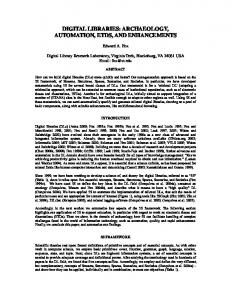
introduce a new scheme based on odd level quantization and 81-PAM or 81-QAM. Figure 1 shows the integrated system for transmission of subband coded images. The image is first filtered and decimated to get a subband image. A level allocating algorithm is applied in order to decide the number of quantization levels to be used on each sample. The lowpass-lowpass band is included in the level allocation algorithm without any further preprocessing. The subband samples are combined and mapped into 81PAM or 81-QAM. The level allocation table, which is required at the receiving end for recombining, is error protected and mapped into 5 PAM/QAM or 25PAM/QAM. The symbols are then transmitted over a white gaussian noise channel. At the receiving end a recombination based on the level allocation table is performed. The image is reconstructed through the final interpolation and filtering. 2. THEORY 2.1 Odd level quantization in source coding. In subband coding of pictures, the pixels in the different subbands are allocated bits block by block according to the power level of the block. When a block is allocated only 1 bit, a pixel near zero in value will be quantized to either a relatively large positive or negative value. This signal amplification leads to “ringing” artifacts in the picture that can be visually annoying. In such cases it is an advantage to use an odd level quantizer with zero representation. In this work we use odd level allocation instead of bit allocation, allocating 0, 3, 9, 27, or 81 levels to each block depending on its power level. The number of levels is a power of 3 in order to still have a simple allocation algorithm and to simplify the channel coding. The level allocation is similar to the bit allocation[2,3], but the division factor is now theoretically 3. It turns out that in practical
81-PAM/ -QAM PAM/QAM
X
Levelallocation
Filtering/ Desim.
Combining
DEMUX
MUX
Map/ err. corr. code
Noise N(0,σ2 )
Quant./ Mapping
Inver. mapping Interpol./ Filt.
Inver. map/ error. correct
Y
Recombining
5/25-PAM/ -QAM Level allocation table
Figure 1: Integrated system for transmission of subband coded images. applications, a division factor of 2.2 gives the best results [4].
transmission. In this article, we therefore use only the term symbol rate.
2.2 Channel coding
2.3 Mappings We need to find the optimal mappings from the source space to the channel space. The advantage of optimized mappings over “random” mappings has been shown earlier[1,4]. The optimal mappings give the minimum distortion in the reconstructed image for a given channel power and bandwidth. Generally, this is quite difficult. We want close points in the source space to be close in the channel space and points that are far away from each other in the source space needs to be far from each other in the channel space. At the same time we want to map the most probable source symbols to the minimum amplitude channel symbols.
2.2.1 81-PAM/QAM As we cannot combine the odd level quantized pixels into 64-PAM or 64-QAM channel symbols, we change from 64-PAM/QAM to 81-PAM or 81-QAM, which is a power of 3. This gives the combination possibilities seen in Table 1. Combination Φ(4) Φ(3,1) Φ(2,2) Φ(2,1,1) Φ(1,1,1,1)
Levels combined 81 27,3 9,9 9,3,3 3,3,3,3
Table 1: Combinations. The combination Φ(2,1,1) is not implemented since it will only be used for maximum one pixel pr. picture at applicable symbol rates. Thus, there is no significant reduction in the picture quality if we leave it out. 2.2.2 Symbol rate vs. bit rate Since we introduce a coding scheme that is not bit oriented, the term bit rate is confusing. The important factor now is the channel symbol rate. In order two compare this new system to older bit oriented systems we need to compare the systems when they use the same bandwidth (i.e., symbol rate) and power for
In this work we have tried two different methods for finding the mappings: Ad-hoc and simulated annealing.
2.3.1 Ad-hoc mappings Here, we find the mapping by using the two rules mentioned earlier. This is easy for 81-PAM, but hard for the Φ(4)-mapping in 81-QAM. This is due to the fact that we are making a mapping from one to two dimensions, which means that each point has more neighbors in the channel space than in the source space. Figure 2 shows a mapping made manually.
a 40
a 0
a -40
"5-QAM"
Figure 2: Φ(2,2) mapping onto 81-PAM. 2.3.2 Simulated annealing [4]. This is a way of finding the mappings through long and not very systematic iterations on a computer. The theory is that we try to find the minimum distortion by, to a certain extent, allowing us to accept mappings with higher distortion than the previous. This way we can move out of local minim. The possibility of accepting a mapping with a higher distortion than the previous is lowered as the iteration goes by. We then end up with a mapping in the end that should have a very low distortion.
25-QAM
Figure 3: QAM signal constellations. In the second method two and two symbols are combined into 25-PAM/QAM and an error correcting code is applied. A Reed-Solomon code with two parity symbols that can correct one symbol error in a block of 24 symbols, was used. The Reed-Solomon code is systematic so that there will be no major change to the channel symbol probabilities. 2.4.1 Error probabilities. 25−PAM
0
10
−2
10
−4
2.4 Side information The level allocation table consists of symbols that take on 5 different values (0 to 4). This side information is needed at the receiving end for recombination. Error free transmission of the level allocation table is of outmost importance. One error in the side information might ruin the picture totally since the mapping from the channel space to the source space then will be wrong.
Sannsyn for symbolfeil
10
−6
10
−8
10
−10
10
−12
10
−14
10
−16
10
20
22
24
26 28 CSNR (dB)
30
32
34
25−QAM
0
10
−2
10
−4
10
Sannsyn for symbolfeil
In earlier work, error free transmission of the side information was assumed. Two ways of coding and transmitting the level allocation table have been compared: Use enough power per symbol to ensure error free transmission or apply some kind of error correcting code.
−6
10
−8
10
−10
10
−12
10
−14
10
−16
10
The first method transmits each sample from the level allocation table as a 5-PAM/QAM symbol. A majority of the blocks are allocated zero levels at the symbol rates we operate. By mapping the zero source symbol to the zero channel symbol, we can reduce the power needed for error free transmission. “5-QAM” is not commonly used, but looks like the constellation shown in Figure 3.
−18
10
10
12
14
16 CSNR (dB)
18
20
22
Figure 4: Symbol error rates for 25-PAM and 25QAM. () 0 errors corrected. (- - -) 1 error corrected.
Figure 4 shows the theoretical probability of symbol-error in the side information using 25-PAM or 25QAM with and without an error correcting code added. An error probability of 10-10 gives in average a error for every 2.4×10⁶ picture which is more than good enough for still pictures and acceptable for video. Acquired channel signal-to-noise ratios for a symbol-error rate of 10 -10 are shown in Table 2. 5-PAM 19.76
25-PAM 30.81
“5-QAM” 14.63
Visually the quality is also improved with less “ringing” around edges and large smooth areas. 3.2 Comparison 64-PAM to 81-PAM Figure 6 shows the picture quality as a function of channel signal-to-noise ratio for Lenna using both 64PAM and 81-PAM as a signaling scheme at a symbol rate of 0.83 symbols/pixel.
25-QAM 19.60
35 34
Table 2: CSNR necessary to achieve symbol error probability of 10-10.
33 32 31 PSNR[dB]
We will later see that a good picture quality is achieved down to ca. 32 dB CSNR for 81-PAM and 20 dB CSNR for 81-QAM. 25-PAM/QAM will therefore give good enough error protection. Thus, by using 5-PAM/”QAM” transmission of the level allocation table is error free even when the total picture quality is very poor. However, this will increase the symbol rate.
30 29 28 27 26
3. RESULTS
25 18
3.1 Source coding Figure 5 shows the PSNR as a function of symbol rate for the picture Lenna. As we can see the improvement in picture quality is about 0.4 dB PSNR for all rates when we use odd level quantizers instead of even level quantizers. Lenna 37
36
20
22
24
26
28 30 CSNR[dB]
32
34
36
38
40
Figure 6: Lenna at 0.083 symbols/pixel. () 81PAM. (- - -) 64-PAM. 81-PAM clearly has an advantage over 64-PAM. At low noise the advantage comes from improved source coding, while the advantage for a noisy channel is even larger. 81-PAM includes a zero symbol which reduces the power needed two transmit 81-PAM. In addition, the 81-PAM symbols have a more “narrow” distribution than 64-PAM. The symbols near zero are more frequently used in 81-PAM than in 64-PAM.
35
3.3 Mappings Figure 7 shows the difference in quality for different mappings from source space to the channel space.
PSNR (dB)
34
33
32
31
30
29 0.03
0.04
0.05
0.06 0.07 0.08 0.09 Symbolrate (symbols/pixel)
0.1
0.11
0.12
Figure 5: Picture quality as a function of channel symbol rate for Lenna. () Combined to 81-level symbols. (- - -) Combined to 64-level symbols.
For PAM the ad-hoc mappings are better for most signal-to-noise ratios. For QAM the mappings made by simulated annealing are better. The reason why we get poorer results with simulated annealing for 81PAM is either that we did not find the global minimum or that the mappings are not optimized for the correct channel signal-to-noise ratio.
Lena PAM
3.4 Comparison 81-PAM vs. 81-QAM
35 34
Lenna
33
36
PSNR (dB)
32
34
31 30
32
29
30
PSNR (dB)
28 27 26 25 15
20
25
30
35
28 26
40
CSNR (dB)
24
Bridge PAM 27
22 26
20
PSNR (dB)
25
18 5
24
10
15
20 25 CSNR (dB)
30
35
40
30
35
40
Bridge 28
23
22
26 21
20 15
24 20
25
30
35
40
PSNR (dB)
CSNR (dB) Lena QAM 36 34
22
32
20
PSNR (dB)
30 28
18
26 24
16 5
22 20 18 5
10
15 CSNR (dB)
20
25
Bridge QAM 27 26
10
15
20 25 CSNR (dB)
Figure 8: Comparison PAM vs. QAM. () QAM with symbol rate 0.11 symbols/pixel. (-⋅-⋅-) PAM with symbol rate 0.11 symbols/pixel. (- - -) QAM with symbol rate 0.08 symbols/pixel. (⋅⋅⋅⋅) PAM with symbol rate 0.08 symbols/pixel.
25
Figure 8 shows the results for transmitting with 81PAM and 81-QAM. The side information is included in the symbol rate using 25-PAM/QAM to transmit the side information including an error correcting Reed-Solomon code.
PSNR (dB)
24 23 22 21 20 19 18 5
10
15 CSNR (dB)
20
25
Figure 7: Picture quality as a function of channel signal-to-noise ratio. () Mapping found with simulated annealing. (- - -) Ad-hoc mapping.
We see that QAM is always better than PAM measured with PSNR, but theoretically PAM requires only half the bandwidth. However, this is not always true visually. When the channel gets very noisy the PAM transmitted picture gets “blurry”, while the QAM transmitted picture has large spots which are more annoying than “blurring”. This is due to the fact that, as
mentioned earlier, finding a good mapping from one to two dimensions is very hard and thus, larger errors occur in the QAM case. The very important lowpasslowpass band is coded mostly with 81 levels. An error here is very annoying. Furthermore, QAM does not have as graceful degradation as PAM has. 4. CONCLUSION Moving away from the traditional bit oriented coding scheme and introducing a number of quantization levels that are a power of 3, can improve the quality of the received picture. Moving from 64-PAM/QAM to 81-PAM/QAM gives an even greater advantage when the channel is noisy. Different methods of finding the mapping from source space to channel space has been tried out. The ad-hoc method gives best result for 81-PAM while the method based on simulated annealing is best for 81-QAM. We have also introduced a way of error free transmission of the side information of subband coded pictures at applicable symbol rates, leaving us a total transmission system for subband-coded pictures. REFERENCES [1] T. A. Ramstad, “Sub-band coder with a simple bit-allocation algorithm, -- a possible candidate for digital mobile telephony?”, in Proc. ICASSP, pp. 203207, 1982. [2] T. A. Ramstad, “Consideration on quantizations and dynamic bit allocation in subband codas”, in Proc. ICASSP, pp. 841-844, 1986. [3] J.M. Lervik and H.R. Eriksen, “Integrated system with subband coding and PAM for image transmission”, Master Thesis, Norwegian Institute. of Tech, Dec. 1992. [4] A. Grøvlen, “Combined digital compression and digital modulation”, Master Thesis, Norwegian Institute. of Tech, Dec. 1994 [5] J. M. Lervik, A. Fuldseth, and T. A. Ramstad, “Combined image subband coding and multilevel modulation for communication over power- and bandwidth limited channels,” in Proc. Workshop on Visual Signal Processing and Communications, New Brunswick, NJ, USA, pp. 173--178, IEEE, Sept. 1994.