298
IEEE ANTENNAS AND WIRELESS PROPAGATION LETTERS, VOL. 5, 2006
Combining Space–Time Coding and Adaptive Sectorization Using Reflectarrays Geoffrey G. Messier, Sean V. Hum, and Michal Okoniewski
Abstract—This letter presents a new code-division multiple-access (CDMA) system architecture that combines space–time block code (STBC) transmission and adaptive sectorization using electronically tunable reflectarrays. The result is a single base station architecture that can use a combination of diversity and spatial division transmission in order to achieve good performance in a wide range of environments. The reflectarray method has the further advantage of implementing both STBC and adaptive sectorization using a single transmit chain and power amplifier. This significantly reduces the cost of deploying a multiple antenna scheme and makes it possible to retrofit combined STBC/adaptive sectorization transmission to existing single antenna base stations already in the field. Index Terms—Code-division multiple-access (CDMA), error vector magnitude, reflectarrays, space–time coding.
I. INTRODUCTION
B
EAMFORMING techniques for cellular base stations can be broadly divided into two groups: spatial division techniques and diversity techniques. Spatial division techniques, such as adaptive sectorization and beamforming, attempt to spatially divide users and tend to perform better in clutter-free environments. Conversely, diversity techniques, such as transmit diversity and space–time coding, attempt to mitigate fading and provide the most benefit in environments with heavy clutter. This presents a cellular network operator with a dilemma. In order to maximize the benefit of using multiple antennas in all the environments served by a network, base stations in cluttered environments should use diversity while base stations in less cluttered locations should use spatial division. However, equipping different base stations with different hardware architectures to support either diversity or spatial division transmission is both expensive and difficult to maintain. This letter presents a single code-division multiple-access (CDMA) base station architecture that uses an electronically tunable reflectarray (ETR) structure to combine both adaptive sectorization and space–time block coding. The benefits of using these two techniques separately are well established. The CDMA network capacity improvement provided by adaptive sectorization has been explored in detail [1]–[4]. The diversity benefit of dual transmit antenna space–time block coding in Manuscript received February 17, 2006; revised April 25, 2006. This research was supported by TRLabs, the Natural Sciences and Engineering Research Council (NSERC) of Canada, the Alberta Informatics Circle of Research Excellence (iCORE) and the Alberta Ingenuity Fund (AIF). The authors are with the Department of Electrical and Computer Engineering at the University of Calgary, Calgary, Alberta, Canada (e-mail:
[email protected]). Digital Object Identifier 10.1109/LAWP.2006.876967
cluttered environments is also well known. The Alamouti space–time block code was originally proposed in [5] and variations on that code have been incorporated into both the IS-2000 and UMTS CDMA standards. The ETR architecture presented in this letter allows each base station in a network to choose the appropriate mix of diversity and spatial division for their specific locations while still allowing the network operator to deploy the same multiple antenna hardware network wide. A second major advantage of this architecture is that both adaptive sectorization and space–time block coding are implemented by manipulating the transmitted signal at RF frequencies. As a result, only one transmit chain and power amplifier (PA) is required per base station sector. This is considerably less expensive than traditional architectures that use several antenna elements with a dedicated transmit chain and amplifier for each element. It also means that this system can be retrofitted to existing single antenna CDMA base stations with only minor changes to baseband processing. It should be noted that the ETR used for this application only requires a small number of elements (with suitable modifications to the feed), since the application is relatively low-gain. This differs from the traditional application of reflectarrays in high-gain applications, and presents a new opportunity for this structure in PCS applications. The work in this letter is based on a technique presented by the authors for performing single PA space–time block coding at RF frequencies (RF STBC) using a dipole antenna structure [6]. However, the work in [6] shares the disadvantage of all diversity systems in that it only offers an improvement in environments with heavy clutter. Implementing RF STBC using an ETR structure that is also capable of adaptive sectorization solves this problem. Section II presents a short description of the system architecture. Section III discusses the reflectarray structure in detail and Section IV uses an error vector magnitude (EVM) measure to evaluate the suitability of an ETR structure for RF STBC. System simulation results are presented in Section V illustrating overall system performance and concluding remarks are made in Section VI. II. SYSTEM ARCHITECTURE The adaptive sectorizor is based on an adaptive antenna array architecture known as an electronically tunable reflectarray [7]. This array type was originally developed for applications requiring high-gain beam patterns characteristic of reflector antennas. It consists of an array of electronically tunable patch antennas fed by a feed horn. The scattering characteristics of each patch antenna, namely the phase of the scattered field, can
1536-1225/$20.00 © 2006 IEEE
MESSIER et al.: COMBINING SPACE–TIME CODING AND ADAPTIVE SECTORIZATION
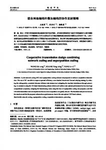
Fig. 1.
299
System architecture.
be manipulated independently through the use of an integrated varactor diode in the antenna element structure. Thus, the array elements can be phased to form the desired beam pattern. The result is an antenna structure fed by a single transmit chain that is capable of beamforming. The phase agility of the antenna elements allows the phase of the RF field in the beam formed by the ETR to be manipulated for modulation purposes. This makes it possible for an ETR performing adaptive sectorization to also simultaneously perform STBC transmission using a technique similar to that in [6]. While only a two-antenna STBC is considered in this letter, the ability of the ETR to modulate to arbitrary phase angles may allow this approach to be extended to systems with more than two antennas. This is a flexibility that was not available with the antenna design presented in [6]. The proposed CDMA base station architecture requires two ETRs and is shown in Fig. 1. The ETRs are spatially separated and are connected to standard duplex filters. On the forward link, a single transmit chain and amplifier is followed by a passive RF splitter with the two splitter outputs connected to the ETRs. On the reverse link, receive diversity is made possible by connecting each ETR to a separate receive chain. The amplitude response of the beams synthesized by both ETRs will be the same and will adjust according to an adaptive sectorization control algorithm [1], [4]. As discussed in [6], STBC transmission is implemented by conjugating the odd numbered information symbols at baseband and then applying a 180 phase shift to one of the transmit antennas during the odd symbol interval. This 180 phase shift is achieved in Fig. 1 by manipulating the phase of ETR 0. It is important to emphasize that this 180 phase shifting does not significantly disturb the amplitude response of the antenna patterns generated by the reflectarrays. As a result, simultaneous adaptive sectorization and STBC transmission is possible. Also, using an RF splitter will reduce the power transmitted by each ETR by 3 dB. However, power is often reduced by 3 dB in transmit diversity systems in order to maintain the same effective radiated power as a single antenna system. III. ETR DESIGN AND IMPLEMENTATION Reflectarray antennas have typically been used as planar replacements for reflector antennas. The introduction of tuning capabilities to the reflectarray elements enables dynamic phasing
Fig. 2.
Measured reflectarray cell scattering characteristics.
of the elements to form adaptive beam patterns. Recent implementations of electronically tunable reflectarrays based on varactor diodes [7] enable the scattered field of the ETR elements to be phased over a broad range, approaching 360 . Phasing of the RF field can be accomplished accurately with only a small change in the amplitude response of element. This implementation not only enables scanning of the beam over a broad range, but also phase modulation of the RF field at very high rates. Since beam forming only relies on the relative phasing between array elements, phase modulation of the beam can be superimposed on top of the array phasing process by simply offsetting all array elements by the desired amount. This capability has made ETRs attractive for uses outside their range of normal applications, including the cellular communications application described here. While the gain offered by typical reflectarrays far exceed that required by this application, a low-gain ETR for implementing the beams described for this application can be realized with suitable modifications to the near-field feed. To realize a model of an ETR for this study, experimental measurements of ETR unit cells used in a previous study were used [7]. A sample cell measurement showing the amplitude and phase response for several frequencies is shown in Fig. 2, where is carrier frequency. The measured scattering characteristics of the reflectarray cell at 5.5 GHz were assumed to apply to a similarly-designed cell operating at PCS frequencies. These cells were formed into an array for covering a sector with the is the free space wavedesired beamwidth. Assuming that length of the carrier, a one-dimensional array with an element was phased according to the measured characspacing of teristic in Fig. 2 to produce a beam phased at the desired beam pointing angle. A one-dimensional array was used in the model as only adaptive sectorization in the azimuth plane was considered for this study. However, additional elements for producing adaptive sectorization in the elevation plane could be added in the same fashion. Two sector designs were considered with approximately 30 and 60 10-dB beamwidths. For the elements used, suitable arrays for producing these beamwidths consisted of five and three elements, respectively. In Fig. 2, a small change in the amplitude of the scattered field is visible as the phase of the reflectarray cell is scanned. Besides affecting antenna efficiency, it can also degrade the amplitude
300
IEEE ANTENNAS AND WIRELESS PROPAGATION LETTERS, VOL. 5, 2006
balance during the 180 phase shifting imposed on consecutive symbols. To compensate for this effect, an optimal set of phases is computed for both symbols such that the amplitude difference between the two resulting beams is minimized. It is emphasized that since the beam shape only depends on relative phasing between elements, the phase of the elements can be offset an arbitrary amount to achieve this. The array factor of the resulting array was computed using the measured element characteristics and the element factor of the cell. Identical ETRs could be used for uplink and downlink transmission since the transmit and receive frequencies are not separated by more than 1% of the carrier frequency, resulting in minimal beam squint issues. The array factor is used in both EVM and system simulations, discussed in the following sections.
Fig. 3. Error vector magnitude: three-element array.
IV. ETR ERROR VECTOR MAGNITUDE PERFORMANCE In [6], it was pointed out that one of the primary limitations of this RF STBC technique is whether the antenna can impose an ideal 180 phase shift during the odd symbol intervals without disturbing the amplitude response of the antenna. An error vector magnitude (EVM) metric was therefore proposed in order to evaluate the quality of the antenna phase shift. A perfect 180 phase shift with no amplitude distortion would mean that , where and are the complex antenna responses during the even and odd symbol intervals, respectively. In other words, the phase of the antenna is inverted but the amplitude response remains the same. As a result, the ideal difference between symbol intervals will . The difference between the actual be and the ideal value of is the error vector. value of Error vector magnitude is defined as
(1) As described in Section III, three- and five-element ETRs are considered in this letter. Plots of EVM versus pointing angle for three different field angles are shown for the three- and fiveelement arrays in Figs. 3 and 4, respectively. The plots show EVM increases for larger azimuth angles. This indicates that the ability of the beams to impose the 180 phase shift degrades near the beam edges. More importantly, the plots indicate that EVM remains below 0.25 even for the larger azimuth angles. In [6], it was shown that the RF STBC method could withstand EVM values of up to 0.3 before a significant performance degradation was observed. This suggests that the ETR implementation of RF STBC should perform well, a conclusion that is confirmed by the CDMA system-level simulations in Section V. V. SYSTEM PERFORMANCE CDMA forward link simulations are used to evaluate the performance of implementing a combination of RF STBC and adaptive sectorization as described in Section II. Downlink communication between the base station and a single mobile is simulated without channel coding. Interference and noise is
Fig. 4.
Error vector magnitude: five-element array.
modeled as a complex AWGN process at the mobile receiver input. The simulation results plot BER versus , where is energy per information bit and is the variance of the AWGN. The spreading rate is 1.2288 Mchip/s, the data rate is 76.8 kb/s and the modulation scheme is QPSK. A fast Rayleigh-fading channel is used with tap weights that correspond to the ITU Vehicular-A model [8]. At the start of each simulation, an ETR beam is synthesized with a particular beamwidth and pointing angle. Beamwidths of 60 and 30 are considered, which correspond to the threeelement and five-element arrays described in Section III, respectively. The synthesized ETR beam patterns and beam phase shifting performance data described in Section III are incorporated into the CDMA simulations in this section to ensure a realistic evaluation of how antenna imperfections affect overall system performance. Ideally, ETR 1 in Fig. 1 would have a phase response of 0 for all symbols, while ETR 0 would have a phase response of exactly 0 for even symbols and 180 for odd symbols. However, the actual phase response of the ETR beams will deviate from this ideal as a function of mobile angular position. Section IV show the result is increasing EVM values as azimuth angle increases and the mobile moves closer to the beam edge. To ensure this phase shift sensitivity to field angle is captured, the mobile is moved around the beam during simulation.
MESSIER et al.: COMBINING SPACE–TIME CODING AND ADAPTIVE SECTORIZATION
301
Fig. 5. CDMA system performance: three-element array.
Fig. 6. CDMA system performance: five-element array.
It is assumed that mobile angular position is a uniformly distributed random variable across the width of the beam. Since softer handoff is not being simulated, the mobile is restricted from entering the beam edges. The mobile is constrained to be for the 60 beam and for within azimuth angles of the 30 beam. To model the worst case, a new random angular mobile position is generated for each information symbol. Forward link performance is evaluated for three scenarios: single antenna transmission, actual ETR STBC and ideal ETR STBC. The single antenna simulations assume the mobile is receiving a transmission only from the beam synthesized by ETR 0. The actual ETR STBC simulations transmit to the mobile using the ETR phase shifting characteristics synthesized as described in Section III. The ideal ETR STBC simulations transmit to the mobile using the synthesized amplitude responses of the ETR beams but with an ideal phase characteristic imposed. This means that ETR 1 always has a phase response of 0 and ETR 0 always has a phase response of either exactly 0 or exactly 180 for all mobile positions. Comparing the ideal ETR STBC and actual ETR STBC allows the effect of the EVM values in Figs. 3 and 4 on overall system performance to be evaluated. The 3 dB reduction in power due to using the splitter in Fig. 1 is also modeled for the ETR STBC and ideal ETR STBC. The results of simulations conducted for ETR beamwidths of 60 and 30 are shown in Figs. 5 and 6, respectively. Each plot shows two sets of curves. The first set demonstrate performance for a beam pointing broadside and the second set demonstrate performance for a beam pointing 20 off broadside. A pointing angle of 20 was chosen since Figs. 3 and 4 indicate that is where EVM is quite large for both beams. Showing BER performance for different pointing angles illustrates how this RF STBC technique will perform when the ETR is also simultaneously steering its beams to implement adaptive sectorization. The simulation results indicate that the RF STBC technique significantly improves system performance when implemented with ETRs. Figs. 5 and 6 also indicate that the performance of ideal ETR STBC is very close to the actual ETR STBC for both the 3 element and 5 element arrays. Only a very slight degradation is seen even for a pointing angle of 20 , the pointing angle with the worst case EVM. The plots also indicate that
the BER results for the pointing angle of 20 off broadside are slightly below the broadside results. This is due to increased scanning loss as the ETR beam is steered away from broadside. VI. CONCLUSION This letter has presented a unique approach for combining space–time block coding and adaptive sectorization into a single system. The result is a single hardware architecture for a base station that is capable of mixing diversity and spatial division multiple antenna techniques in order to perform well in a wide variety of environments. The electronically tunable reflectarray architecture implements both RF STBC and adaptive sectorization with a single transmit chain and amplifier, making this system potentially very low cost. Simulations were performed that show RF STBC implemented with an ETR will significantly improve downlink performance with only minor degradation due to antenna phase shift imperfections. REFERENCES [1] C. U. Saraydar and A. Yener, “Adaptive cell sectorization for CDMA systems,” IEEE J. Sel. Areas Commun., vol. 19, no. 6, pp. 1041–1051, Jun. 2001. [2] J. C. Yun, P. Choi, J. H. Lee, J. W. Byun, and M. S. Lee, “Traffic balancing performance of adaptive sectorized systems,” in Proc.2002 IEEE 56th Veh. Technol. Conf. Fall (VTC 2002-Fall), vol. 3, Sep. 2002, pp. 1878–1881. [3] R. Giuliano, F. Mazzenga, and F. Vatalaro, “Adaptive cell sectorization for UMTS third generation CDMA systems,” in Proc. 2001 IEEE 53rd Veh. Technol. Conf. Spring (VTC 2001-Spring), vol. 1, May 2001, pp. 219–223. [4] J. Zhang, J. Liu, Q. Zhang, W. Zhu, B. Li, and Y. Q. Zhang, “An efficient algorithm for adaptive cell sectorizing in CDMA systems,” in Proc. 2003 IEEE Int. Conf. Commun. (ICC 2003), vol. 2, May 2003, pp. 1238–1242. [5] S. M. Alamouti, “A simple transmit diversity technique for wireless communications,” IEEE J. Sel. Areas Commun., vol. 16, no. 8, pp. 1451–1458, Oct. 1998. [6] G. G. Messier, A. Sutinjo, S. V. Hum, and M. Okoniewski, “A space time coding scheme utilizing phase shifting antennas at RF frequencies,” IEEE Antennas Wireless Propag. Lett., vol. 4, pp. 369–372, 2005. [7] S. V. Hum, M. Okoniewski, and R. J. Davies, “Realizing an electronically tunable reflectarray using varactor diode-tuned elements,” IEEE Microw. Wireless Compon. Lett., vol. 15, no. 6, Jun. 2005. [8] International Telecommunications Union, “Guidelines for Evaluations of Radio Transmission Technologies for IMT-2000,” ITU ITU-R M.1225, 1997.