undertake missions like border patrol, surveillance and in ... border patrol, surveillance and in active combat both as a ..... tracking for uav video application.â.
International Journal For Technological Research In Engineering Volume 1, Issue 9, May-2014
ISSN (Online): 2347 - 4718
COMMAND CONTROLLED ROBOT FOR MILITARY PURPOSE Mithileysh Sathiyanarayanan1, IEEE Student Member, Syed Azharuddin2 Santhosh Kumar3, Gibran Khan4 Electronics and Communication Engineering Department Rajiv Gandhi Institute of Technology, Bangalore, India Abstract—Robots for military purposes, in general, called as Unmanned ground vehicle (UGV) are used to augment the soldiers capability. These types of robots are generally capable of operating outdoors and over a wide variety of terrain, functioning in place of humans. Though there are many developments in the robotics field, we built a prototype command controlled robot (called as UGV) to undertake missions like border patrol, surveillance and in active combat both as a standalone unit (automatic) as well as in co-ordination with human soldiers (manual). We use a specific mode called, command control mode. In this mode, UGV is manoeuvred wirelessly by transmitting navigation commands from the base station based on the video received from the on-board camera. Also, in this mode, turret is wirelessly controlled in order to locate and eliminate targets in the field of vision. The complete set up and working of the command control mode UGV are described in the paper. Index Terms—Unmanned ground vehicle, robots, command control mode, Arduino, GPS. I. INTRODUCTION In the last decade, many robots have been built for various purposes. Our main focus is on the military purpose robots. Due to the terrorism and insurgency problems faced by the people, governments and scientists across the globe are working day and night in order to bring these problems under control. Billions of dollars are spent by nations for the research of new defense systems which are capable of safeguarding citizens from terrorist threats. This motivated our group to develop prototype command controlled unmanned ground vehicle (UGV) to undertake missions like border patrol, surveillance and in active combat both as a standalone unit (automatic) as well as in co-ordination with human soldiers (manual) [1], [2], [3]. To make it clear, an unmanned ground vehicle (UGV) is a vehicle that operates on land (ground) with or without humans presence for giving navigation commands and decision making [4]. In this paper, we have considered humans decision making and providing navigation commands based on the live video signal received from the camera mounted on the UGV. One of our motivations for this project is the Foster-Miller TALON robot [5]. It is a small military robot intended for missions going from surveillance to battle (combat). In excess of 3000 TALON robots have been deployed to battle theatres. FosterMiller claims “the TALON is one of the fastest robots in production, one that can travel through sand, water, and snow (up to 100 feet deep) as well as climb stairs”. The TALON
www.ijtre.com
transmits in color, dark and white, infra-red, and/or night vision to its administrator or controller, who may be 1000 m away. It can run off lithium-Ion batteries for a most extreme of 7 days on standby independently before requiring charging. It has a 8.5 hour battery life at typical working speeds, 2 standard lead batteries giving 2 hours each and 1 optional Lithium Ion giving an extra 4.5 hours. It can additionally withstand long time in tainted territories. Different types of Talon developed are as follows [5]: Regular (IED/EOD) TALON: Carries sensors and an automated controller, which is utilized by the U.S. Military for disarming improvised explosive devices and dangerous arms transfer (explosive ordnance disposal) Special Operations TALON (SOTAL): Does not have the mechanical arm controller yet conveys day/night color cameras and listening gadgets; lighter because of the nonappearance of the arm, for observation missions. SWORDS TALON: For small arms combat and guard roles. HAZMAT TALON: Uses chemical, gas, temperature, and radiation sensors that are shown in real time to the users on a hand-held presentation unit. It is been tested by the US Armament Research Development and Engineering Center ARDEC. So, this Foster-Miller TALON robot motivated us to develop command control mode operating the unmanned ground vehicle for military purposes which are generally capable of operating outdoors and over a wide variety of terrain, functioning in place of humans. Our aim is to develop prototype UGV to undertake missions like border patrol and surveillance. So, in this paper we explain the set up and design of the unmanned group vehicle which will be controlled using commands from the base station. The rest of the paper is organized as follows. In Section II we explain the concept of command control mode for operating UGV. In Section III, we explain the results. Section IV concludes our discussions in this paper. II. COMMAND CONTROL MODE The aim of this mode is to enable operation of unmanned ground vehicle using inputs which could vary from a simple computer keyboard to other self-designed input devices. The commands are sent over to the UGV remotely using wireless communication technologies such as ZigBee or internet, while it transfers live video feedback to the user. ZigBee is a wireless technology designed to connect simple high-tech devices for useful purposes. The main tasks of the command control mode are: Maneuver the UGV wirelessly by transmitting navigation commands from the base station based on the video received
Copyright 2014.All rights reserved.
1029
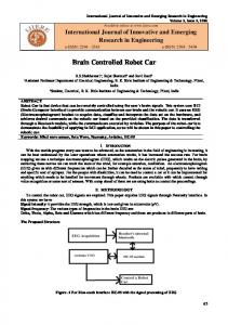
International Journal For Technological Research In Engineering Volume 1, Issue 9, May-2014 from the on-board camera. Control the turret wirelessly in order to locate and eliminate targets in the field of vision. For these tasks to be performed, we considered „Arduino‟. It is an open-source software and easy-to-use hardware. Writing code and uploading it to the i/o board is very easy and simple. The other parts around arduino are built systematically as shown in the block diagram figure 1. A. Block diagram of command control mode The block diagram of command control mode for operating unmanned ground vehicle is shown in figure 1. The role of each blocks in the diagram are explained in detail. 1) Base station: It‟s a computer system located at a remote place away from the UGV which controls it using keyboard, mouse for mode control, movement and live video feedback for monitoring the environment. 2) Keyboard and mouse: They are used to handle the motion of the UGV and the movement of the turret for wide angle vision. 3) 3G Internet: Communication medium for system to system interaction so as to control the UGV wirelessly. 4) On-board system: A computer system placed on the UGV itself which receives the commands and delivers it to the control Unit. 5) Camera: An image acquiring device which provides the video required for UGV vision. 6) Control Unit: It‟s the Arduino microcontroller which receives signals from the user and other sensors and performs tasks such as turret movement and UGV movement. 7) GPS Unit: A navigation system used in the autonomous mode for obtaining location coordinates. 8) Compass: To acquire the direction to which the UGV is facing. 9) IR sensors: Infra-red Sensors used in the obstacle avoidance mechanism incorporated into the autonomous mode. 10) Servo motor: they are used to control the direction turn of the UGV and the 2 axis movement of the turret. 11) DC motor: These are used mainly for the UGV movement. 12) Li-PO Battery and voltage regulator: the power source supplying the entire UGV with voltage regulation to provide optimum power ratings. 13) Wireless modem: Zigbee to provide wireless data trans-fer for auto mode. 14) IMU: An inertial measurement unit which tracks the orientation of the hand used for hand Gesture control (ArmCon mode). 15) Ni-Cd battery: Used for powering up the Control Unit, Zigbee and the IMU.
www.ijtre.com
ISSN (Online): 2347 - 4718
The hardware components used in the Unmanned ground vehicle are: ARDUINO MICROCONTROLLER SERVO MOTOR DC MOTOR INERTIAL MEASUREMENT UNIT ZIGBEE RADIO MODEM 78XX ICS ELECTROMAGNETIC COMPASS MODULE GPS RECIEVER SYSTEM H-BRIDGE LITHIUM POLYMER BATTERY FTDI CHIP WEBCAM 2X RELAY BOARD IR SENSORS NICKEL-CADMIUM BATTERY B. Algorithm design for command control mode The algorithm design for command control mode is quite easy and straightforward. We considered two sides for building a prototype UGV: Base station/user side and UGV side. B.1 Base station/user side: Navigation commands such as up, down, left and right arrow keys in computer keyboard have been assigned for rover (UGV) movement. The keys pressed have been mapped into specific characters which are sent as control signals to the arduino controller. The characters sent have their unique function assigned to them which is shown. B.2 UGV side: UGV transmits video signals from the on-board camera to obtain navigation commands. Once the navigation commands are obtained, UGV monitors serial input for the received characters and makes the subsequent decisions. The following functions are executed in response to the character sent [up (), down (), left (), right (), halt ()]. We have provided clockwise and anticlockwise pin assignment for forward and reverse movement of the UGV. Dedicated PWM signal pin for 80 - 120 degrees range of servo turn is maintained and H - Bridge Enable control is being utilized for braking. Also, in this mode, turret is wirelessly controlled in order to locate targets in the field of vision. At the base station side, commands controls from the computer keyboard will be given as shown in figure 3. Based on the commands from computer keyboard such as up, down, left and right arrow keys have been assigned for rover (UGV) movement. The specific keys pressed are been mapped into arduino controller. Once the control signals are obtained, the following functions will be executed by the UGV. The flow chart of command control mode for operating unmanned ground vehicle is shown in figure 2. The role of both base station side and UGV side are shown.
Copyright 2014.All rights reserved.
1030
International Journal For Technological Research In Engineering Volume 1, Issue 9, May-2014
Fig. 1. Block diagram for the command control mode.
Fig. 2. Flow chart for the command control mode. III. RESULTS We successfully built a stand-alone rover (UGV) capable of being controlled using command control signals wirelessly from the base station as shown in figure 4. Rotating camera platform was set-up that can target the enemy with/without human control. We have made use of modern communication
ISSN (Online): 2347 - 4718
Fig. 4. Prototype command controlled unmanned ground vehicle (UGV) IV. CONCLUSION AND FUTURE WORKS We successfully built a prototype UGV capable of being controlled using command control signals wirelessly from the base station. New technologies like Zigbee and Arduino have been implemented. We used a specific mode called command control mode. In this mode, UGV is manoeuvred wirelessly by transmitting navigation commands from the base station based on the video received from the on-board camera. Also, in this mode, turret is wirelessly controlled in order to locate targets in the field of vision. The complete set up and working of the command control mode UGV are described in the paper. We have a strong feeling; these kinds of robots can be used for military purposes to augment the soldiers capability. They are generally capable of operating outdoors and over a wide variety of terrain, functioning in place of humans. This UGV can undertake missions like border patrol, surveillance and in active combat both as a standalone unit (automatic) as well as in co-ordination with human soldiers (manual). Our future work is on developing automatic mode along with command control mode which will include motion tracking, obstacle detection, path planning, gesture control and GPS. V. ACKNOWLEDGEMENT We are really thankful to Prof. Balachandra K.V sir for his invaluable constructive comments and ideas.
Fig. 3. Navigation commands for the command control mode UGV. advancement such as 3G services to provide ease of access and portability to our UGV. Other new technologies like Zigbee and Arduino have been implemented. The working of the UGV was demonstrated at the RGIT workshop, Bangalore (in June 2011) and successfully passed the test.
www.ijtre.com
REFERENCES [1] S. Kumar and P. Awasthi, “Navigation architecture for autonomous surveillance rover.” [2] P. Z. Wenshuai Yua, Xuchu Yub and J. Zhoui, “A new framework of moving target detection and tracking for uav video application.” [3] S. Berman and Y. Edal, “Evaluation automatic guided vehicle systems,” 2008. [4] http://en.wikipedia.org/wiki/Unmanned ground vehiclel. [5] http://www.army-guide.com/eng/product1795.html, 2002.
Copyright 2014.All rights reserved.
1031