The so called shorted arrays form a special class .... identity element E and the inversion element i. .... which the fluxons propagate only in the horizontal rows, in.
PHYSICAL REVIEW B
VOLUME 55, NUMBER 13
1 APRIL 1997-I
Comparative dynamics of two-dimensional shorted arrays and continuous stacked Josephson junctions A. Petraglia and N. F. Pedersen Department of Physics, The Technical University of Denmark, DK-2800 Lyngby, Denmark
P. L. Christiansen Institute of Mathematical Modelling, The Technical University of Denmark, DK-2800 Lyngby, Denmark
A. V. Ustinov Institute for Thin Film and Ion Technology, Research Center (KFA), D-52425 Ju¨lich, Germany ~Received 4 April 1996; revised manuscript received 17 October 1996! Multilayer structures of Josephson junctions are discussed both in the continuous and the discrete case. For the continuous case some recent results are shown. For two-dimensional shorted arrays, which account for the discrete limit, a model is presented. Analytical and numerical calculations show typical features of coupled sine-Gordon systems such as the splitting of the limit velocity and modes of different symmetry which correspond to the different velocities. The discretization, however, adds interesting features, the most prominent of them being a strong interaction between solitons and discreteness-induced plasma waves. @S0163-1829~97!05009-1#
I. INTRODUCTION
Josephson junctions, involving nonlinear behavior, quantum effects, and high-frequency electromagnetic-wave propagation, are good candidates for a wide range of applications. The most important ones are superconducting quantum interference devices, Josephson voltage standards, logic elements, and oscillators. For the oscillators, typical highfrequency cutoffs are in the range of hundreds of GHz. Josephson flux-flow oscillators have rather low power of the emitted radiation and low output impedance, which are essential drawbacks for their utilization in practical circuits. Indeed, the maximum power involved is of the order of microwatts, and the output impedance is of the order of a few Ohms.1 Increasing these values by at least an order of magnitude would largely extend the range of application of these devices. An obvious way to overcome these problems is to use systems of coupled junctions. Arrays of series-connected short junctions have been extensively studied both from the experimental and theoretical points of view.2 In the last few years the research focused on one-dimensional ~1D! parallel arrays,3,4 and 2D arrays with both non-negligible and negligible self-field effects ~see Refs. 5 and 6 for a list of references on this subject!. The so called shorted arrays form a special class of 2D arrays; their elementary cell has Josephson junctions only in one spatial direction, while in the other direction it is formed by superconducting wires.7,8 Arrays of long junctions form another class of coupled systems. Among them, vertically stacked junctions are interesting for many reasons: their coherent operation shows promising improvements for practical applications.9 Furthermore they may also serve as a model for naturally anisotropic high-T c crystals.10,11 In this work we study shorted arrays emphasizing their analogies and differences from the stacked long Josephson 0163-1829/97/55~13!/8490~7!/$10.00
55
junctions. We show that their dynamic equations are indeed closely related to the model by Sakai, Bodin, and Pedersen12 of stacked junctions. The paper is structured as follows. In Sec. II an introduction to the topic of stacked junctions is given. We present the model and a summary of its most important features together with some recent original results. Links to the experiments will also be given. In Sec. III the 2D arrays are introduced and analyzed. In Sec. III A a model for the shorted arrays is presented. The neutral stability, i.e., the independence of the phase dynamics in different rows in zero magnetic field,7 can simply be deduced from this model. In Sec. III B the dynamical behavior of shorted arrays is studied both analytically and numerically. The splitting of the limit velocities and the discretization effects are the main features of the dynamics. The velocity splitting arises in analogy with stacked long junctions. The discreteness forces the travelling kinks to emit radiation; the nonlinear interaction between kinks and their radiation has important effects on the dynamics of the kinks. Current Voltage characteristics are also calculated to allow direct comparison with experiments. II. CONTINUOUS CASE: STACKED JUNCTIONS
A Josephson stack consists of a set of superconducting layers interleaved by insulating layers. The model for a generic N-layer stack of long junctions was proposed in a complete form by Sakai, Bodin, and Pedersen in Ref. 12, but the basic ideas can already be found in other precedent works such as in Ref. 13. In it they suppose the interaction between junctions acts through the magnetic field penetration in the superconducting layers. From the experimental point of view stacked structures of long Josephson junctions have been extensively studied.9 The observation of the limit velocity splitting9 stimulated more detailed theoretical investigations14 and also led to a 8490
© 1997 The American Physical Society
55
COMPARATIVE DYNAMICS OF TWO-DIMENSIONAL . . .
8491
Let us consider the two cases ~i! N even, the reducible representation character table of the base shown in Fig. 1~a! is ~n!
G
E
i
N
0
remember that the irreducible representations character table of the inversion group C i is ~see, e.g, Ref. 19!
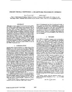
FIG. 1. Symmetry-representation of stacked system. Directions for the positive displacement of the phases for the classification of the modes are indicated by arrows. The points represent the junctions, the dashed line is the main axis of symmetry. ~a! N even; ~b! N odd (N is the number of junctions!.
very detailed comparison of theory with experiments.15 The normalized form of the dynamical equations, assuming identical junctions and overlap geometry, are ˆ¯ ] xx w 5M J
~1!
where ] xx is the second order space derivative, w is the vector of the gauge invariant superconducting phase differences across each layer, ¯ J is the vector of the total current densities ˆ is the interaction maflowing through the junctions, and M trix; it has a tridiagonal form with ones on the main diagonal and 2D in the upper and lower diagonal. The parameter D is a measure of the interaction between junctions, and depends on the geometric and physical parameters of the system.12 It is always non-negative. Equation ~1! has been extensively studied in literature from both analytical and numerical points of view;10,14–18 the main results obtained are ~i! For an N-layer system there are N different limiting velocities of the waves. The explicit formulas for the velocities are10,15 c n5
A
1 np 122D cos N11
,
n51,2, . . . ,N,
~2!
where the characteristic velocity ¯ c of an isolated single junction has been taken equal to the unity. ~ii! Some of the velocities of the waves are larger than the single-junction characteristic velocity. ~iii! Different modes along the vertical axes correspond to each velocity. In particular, the number of antisymmetric modes is equal (N even! to or exceeded by one (N odd! the number of symmetric modes. The latter result can be obtained in a simple and elegant way. The only property used is the invariance of the stack with respect to a symmetry transformation. Let us consider the 1D problem. Figure 1 shows the schematic drawing of the system: the points represent the junctions; the dashed line is the main axis of symmetry. The two cases of even and odd N are shown separately: in the former case ~a! the mirror axis lies between the two inner junctions, in the latter ~b! it crosses the middle junction. The symmetry group of the system is C i : 19 It has only the identity element E and the inversion element i.
Ci
E
i
Ag
1
1
Au
1
21
symmetric antisymmetric.
Using standard techniques, we can decompose the reducible representation G (N) in terms of an equal number of symmetric (A g ) and antisymmetric (A u ) irreducible representations of C i N N G ~ N !5 A g1 A u 2 2
~3!
meaning that we have an equal number (N/2) of symmetric and antisymmetric modes. ~ii! N odd; the reducible representation of the base in Fig. 1 ~b! is E G
~N!
i
N 21
and G (N) decomposes in G ~ N !5
N21 N11 A g1 Au , 2 2
~4!
i.e., we have (N21)/2 symmetric and (N11)/2 antisymmetric modes. The above information can be fruitfully used for possible states of the junctions. Let us consider N52. According to Eq. ~3!, there is one antisymmetric mode ~in-phase! and one symmetric mode ~out-of-phase!. Thus, for the first case we can take the ansatz ~note that we explicitly assume the perturbation-free case a , g 50, see discussion below!
w 1 ~ x,t ! [ w 2 ~ x,t ! .
~5!
Thus, Eq. ~1! becomes
w j,xx 5 ~ 12D !~ w j,tt 1sinw j ! ,
j51,2
~6!
Equation ~6! is a set of two uncoupled equations having the same form. Each term of the set is a sine-Gordon equation, which can be written in the canonical form normalizing x by A12D. Consequently the limit velocity of waves is c 15
1
A12D
.
~7!
This is a well-known result which can be extended to the in-phase mode of N-layers systems and moreover, is in agreement with numerical simulations cited above. It is more general than Eq. ~2!. For while Eq. ~2! regards only small plasma waves, Eq. ~7! is related to any kind of solutions which obey Eq. ~5!. For the out-of-phase case we can assume
PETRAGLIA, PEDERSEN, CHRISTIANSEN, AND USTINOV
8492
55
from the same node is I vi, j . We will assume the array to have N r rows and N c columns. A. Model
In the following, we write the equations of the circuit. Here we will use the approach suggested by Lucheroni.22 It differs from classical approaches by accounting for the BiotSavart law in the fluxoid quantization formula. Consequently, the procedure we will follow here is different from that we used earlier.8 Neglecting the mutual inductance, the flux quantization in the loop i, j is
w i, j 2 w i11,j 5
FIG. 2. Equivalent circuit of the shorted array, i51, . . . ,N c ; j51, . . . ,N r . The array is supposed to be periodic in the horizontal direction and open in the vertical direction.
w 1 ~ x,t ! 52 w 2 ~ x,t ! .
~8!
This gives also a set of two uncoupled similar equations. They have the form
w j,xx 5 ~ 11D !~ w j,tt 1sinw j ! ,
i51,2
~9!
where w i, j is the gauge invariant phase across the junction (i, j). The phase w i, j is a function of the normalized time t. The term h accounts for the external magnetic field, in the following we will consider the case h 50; moreover, to keep things simple we will restrict ourselves to the geometry with periodic boundary conditions in the horizontal direction ~we suppose that the points i5N c 11 and i51 coincide with each other!. Subtracting from Eq. ~11! the same equation written for the point i21,j and using the Kirchhoffs laws for the nodes i, j and i, j11, h I i,h j11 2I i21,j11 5I vi, j 2I vi, j11 ;
and are characterized by the limit velocity 2
c 5
1
A11D
2p v v ~ L I i, j 1L h I i,h j11 2L v I vi11,j 2L h I hi, j ! 1 h ; F0 ~11!
I hi21,j 2I hi, j 5I vi, j 2I vi, j21 , .
~10!
Note that while a bias g does not change the results for the in-phase mode, it changes the equations for the out-ofphase mode. However, the matching of the equations can be restored by choosing a proper bias configuration ~i.e., bias in one layer should be opposite to the bias in the other layer.20! Finally, we recall some works18,21 about the stability of the solutions in Eq. ~5! and Eq. ~8!. The main result is that the stability drastically depends on the parameter region. The most important parameter is the velocity of the waves, but also the damping terms play an important roˆle. III. DISCRETE CASE: SHORTED 2D ARRAYS
Shorted arrays are square-cell 2D Josephson-junction arrays having horizontal branches shorted by superconductors. A possible way to make them is using long superconducting wires connected by rows of junctions in parallel. Figure 2 shows a schematic drawing, where we assume all the circuit parameters to be equal. Each horizontal branch consists of an inductance L h while the vertical branches are formed by the inductance L v in series with a Josephson junction. We consider a homogeneous biasing of the whole array at which the bias is modeled by a dc current source ~with current I B ) in parallel with each junction; in Fig. 2 it is included in the junction symbol. The horizontal branch current flowing from the node i, j is I hi, j , while the vertical branch current flowing
~12!
we obtain D 2i w i, j 5
2p @ 2 ~ L v 1L h ! I vi, j 2L h ~ I vi, j11 2I vi, j21 ! F0 2L v ~ I vi11,j 1I vi21,j !# ; i51, . . . ,N c ,
j51, . . . ,N r , ~13!
v where D 2i w i, j [ w i11,j 22 w i, j 1 w i21,j . The current I h, i, j is the sum of the resistively shunted junction term and the bias current I B . We choose the upper and lower boundary condiv tions to be I i,N 5I vi,050. Equation ~13! can be written in r 11 normalized form. For this purpose we define
D r[
Lh , 2 ~ L 1L h !
~14!
D c[
Lv , 2 ~ L 1L h !
~15!
2 p ~ 2L v 12L h ! I c . F0
~16!
b L[
v
v
The quantities D r and D c measure the coupling between rows and columns, respectively. The quantity b L is a measure of the discreteness of the array ~for a discussion see Ref.
COMPARATIVE DYNAMICS OF TWO-DIMENSIONAL . . .
55
5!; the limit b L →0 corresponds to the continuous case. The constant I c in Eq. ~16! is the critical current of the junctions. Equation ~13!, thus, becomes 1 2 D w 5 g i, j 2D r ~ g i, j11 2 g i, j21 ! 2D c ~ g i11,j 1 g i21,j ! , b L i i, j ~17! Here, g i, j is the normalized current flowing through the junction at (i, j), it is related with the phase w i, j through the formula
g i, j 5 w¨ i, j 1 a w˙ i, j 1sinw i, j 1I B /I c .
~18!
Equation ~17! relates the second order phase difference along the rows with the normalized currents g i, j in the other rows and columns. In the following we consider the case in which the fluxons propagate only in the horizontal rows, in analogy with the continuous case; this corresponds the vertical inductance L v being negligible, and consequently D c 50, D r 51/2. The most general case, in which L v Þ0, presents many features in common with regular 2D systems ~see discussion by Wiesenfeld et al. in Ref. 7!. Moreover, considering mutual inductances in the model above we can have D r ,1/2 when L v 50; these values can give a better agreement with experiments. We leave the analysis of these models for the future work. Equation ~17! can be written as 1 2 ˆ gj , D w 5M bL i j
~19!
j51, . . . ,N r
where we used the matrix form. The vectors w j , g j and the ˆ are defined as matrix M
SD SD w1j
8493
in individual junctions.7 Indeed, if there is no j-dependent excitations ~vortices!, we have the left hand side of Eq. ~19! ˆ is nonsingular, this means g j 50 or, equal to zero. Since M in other words, every junction moves independently from others. Note that D 2i w j 50 is no longer valid if the symmetry of the phases is broken ~e.g., by applying an external field, having vortices propagating in the array, having different parameters for different junctions, or using an external load!. B. Dynamics of the shorted arrays
Equation ~19! has many features in common with Eq. ~1!. Their main difference is the presence of the second order phase difference in the former case, and the second order derivative of the phase variable in the latter case. This analogy allows us to extend the ideas and many of the results already known for stacked junctions to the discrete shorted arrays. Recent experiments by Duwel et al.23 have shown the splitting of the limit velocity for a two row array. The observation of the flux-flow step accounts for a train of fluxons injected in the array by an external magnetic field and bias current. The limiting voltage position of the step is known to be proportional to the velocity of fluxons. Thus, the splitting of the step is the evidence for the splitting of the limit velocity in the arrays. In our model, this can be shown using linear analysis. For the linear analysis we assume small amplitude oscillations with sinw.w and a 50 in the formula for g i . Thus, Eq. ~19! becomes 1 2 ˆ ~¨ D w 5M f j1w j !, bL i j
j51, . . . ,N r .
~23!
Inserting the linear waves solution
A
w j[
wij
;
~20!
;
~21!
A
w Nc j
g1j A
g j[
gij A
ˆ[ M
S
g Nc j
1 2D 0
r
2D r
0
1
2D
�
�
A 0
2D •••
0
•••
0 A
r
r
�
0
1
2D
2D
r
1
r
D
.
~22!
ˆ is a square N r 3N r matrix. Note that it takes The matrix M the same form as the one for the continuous case substituting D by D r . Under some special conditions Eq. ~19! gives the neutral stability, i.e., the independence of the dynamics of the phases
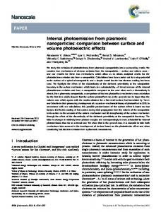
FIG. 3. Current-voltage characteristics for a fluxon-fluxon state in an 2320 shorted array ~points! and an equivalent twofold stack of continuous junctions ~continuous curve!. Parameters for the discrete case are a 50.1, b L 51. For the continuous case L520, a 50.1, D50.5. The voltages are equal in both rows ~and junctions!.
PETRAGLIA, PEDERSEN, CHRISTIANSEN, AND USTINOV
8494
55
FIG. 4. Snapshots of ] t w j (t) in the two rows of the shorted arrays for the bias points marked in Fig. 3. Fluxons are the large peaks. ~a! Point A, the higher velocity mode. The fluxons are in-phase. ~b! Point B, the lower velocity mode. Fluxons are shifted.
¯ expA21 ~ ki Ab 2 v t ! ; w 5A L
i51, . . . ,N c ,
~24!
with the vector of the amplitudes ¯ A , the wave number k, and the frequency v , we obtain
F
2
S DG
k Ab L 4 sin2 bL 2
¯ ˆ¯ A 5 ~ 12 v 2 ! M A.
~25!
This homogeneous linear equation admits solutions when the eigenvalues of the matrix
S
•••
D
S
0
S
D
S
0
�
�
�
0
S
D
S
0
S
D
A 0
•••
0 A
D
S D
np , N r 11
v n5
~27!
vn 1 5 k k
A
S D S D
4 k Ab L sin2 bL 2 11 , np r 122D cos N r 11 n51, . . . ,N r . ~28!
Equation ~28! determines N r different velocities of the plasma waves. In the continuous limit ( b L →0) it is analogous to Eq. ~2!. For zero coupling (D r 50) it corresponds to the velocity calculated for the single row case in Ref. 3. The amplitudes of the waves are given by the eigen vectors corresponding to the eigenvalues of Eq. ~27!
n51, . . . ,N r ;
Consequently, we obtain the dispersion relations
n51, . . . ,N r .
The corresponding phase velocities are
~26!
are zero. Here D52(4)/( b L )sin2@(kAb L )/2 # 2(12 v 2 ), and S5D r (12 v 2 ). The eigenvalues of the matrix ~26! are24 D12S cos
S D S D
4 k Ab L sin2 bL 2 v 2n 511 , np r 122D cos N r 11
A nj 5
A
S D
2 jn p sin , N r 11 N r 11
n, j51,2, . . . ,N r ; ~29!
55
COMPARATIVE DYNAMICS OF TWO-DIMENSIONAL . . .
8495
where v is its velocity. Assuming that the kink velocity can not exceed the limit velocity, we get the following implicit constraint on the m values m.
FIG. 5. Voltage positions of steps for the shorted array; parameters and dynamic state are the same as in Fig. 3. Circles: the higher velocity mode. Squares: the lower velocity mode. For both cases the solid markers correspond to Eq. ~31! while the hollow markers correspond to the numerical results.
where, the index n relates to the velocity, and the index j to the rows. This is exactly the same as the stacked one,14 meaning that the relationship between the symmetry of the modes and the different velocities applies also to the discrete system as well. Below, we will show some numerical simulations which agree with the results given above; however, a complete stability analysis for these modes should still be done. For arrays, the given linear analysis cannot directly be extended to the nonlinear ~fluxon! modes. Indeed, Ustinov, Malomed, and Cirillo3 carried out a complete analysis of the single row case in which they showed that the effect of the discreteness becomes very important through the interaction of fluxon modes with the background plasma waves. Such analysis can be extended to the multirow case considering independently every mode of the fluxon waves @i.e., each value of n in Eq. ~28!#. When the nonlinear kink interacts with the cavity modes with wave number k m 52 p m/L, for a system of a finite length L, the resonance between the kink frequency and the linear wave frequency may take place at velocities
v n,m 5
L 2pm
A
S
D
4 p m Ab L sin2 bL L , 11 np r 122D cos N r 11
S D
n51, . . . ,N r , m51, . . . ,
L
Ab L
. ~30!
Here we assumed that there is a single kink trapped in one row. The kink revolves in the system due to the periodic boundary conditions and the kink frequency is f f l 5 v /L,
L 2p
A
11
S
D
S D
p m Ab L np 4 . sin2 22D r cos bL L N r 11
~31!
Equation ~30! together with Eq. ~31! accounts for possible resonant velocities of a fluxon moving in a shorted 2D array. Thus, a comparison with experiments and numerical calculations can be made here. In Fig. 3 we show a numerical example of the currentvoltage characteristics of a 2320 array with periodic boundary conditions and the parameters a 50.1, b L 51, as well as the current-voltage characteristics of the continuous system with the same parameters ~i.e., L5N r 3 Ab L 520, see Ref. 5, and D5D r 50.5). The voltage is normalized through the relation V52 p v /L, where v is the fluxon velocity. Practically, we integrated Eq. ~19! with a Bulirsch-Stoer routine.25 For Eq. ~1! we used the technique described in Ref. 5 with a5Dx50.1 to transform it from a system of coupled partial differential equations to a system of coupled ordinary differential equation, then we applied the Bulirsch Stoer routine. We choose a kink in each junction as initial conditions; similar current-voltage curves with different stability ranges were obtained for a kink just in one junction. After a suitable transient, of the order of some hundreds normalized time units, we took the voltage across the layer following the Josephson normalized equation V5D w /DT , where we used DT5400 for shorted and DT5100 for stacked junctions ~this difference because the continuous system present smoother dynamics and shorter transient than the discrete one!. The two singularities of the stacked junction curve correspond to the two velocities of Eq. ~2!. The underlying dynamical state consists of one fluxon trapped in each layer. For this dynamics the voltage resulted to be equal in both junctions. For the higher voltage step two fluxons move in a bunched mode ~one below the other!, for the lower voltage step the fluxons move independently ~there is a spatial shift between them!. For the discrete array, the singularities correspond to the velocities given by Eq. ~30!. The two families of curves correspond to the two states analogous to those of the continuous case. The presence of more than one singularity for each state is due to the effect of the discretization ~through the parameter m). In Figs. 4~a! and 4~b! two snapshots of the instantaneous phases ~in the form of their time derivatives! are shown for the marked points in Fig. 3. In the higher voltage branches, marked A in Fig. 3 and shown in Fig. 4~a!, the two fluxons ~large peaks! are exactly in-phase. In the lower voltage branches, marked B in Fig. 3 and shown in Fig. 4~b!, the two fluxons are out-of-phase; the irregularity in the dynamics is due to the interaction of the fluxon frequency f f l and the wave frequency @calculated from Eq. ~30!#. In both cases shown as example the fluxons are locked with m57 plasma waves. The numerical results are in agreement with the above carried analysis. This is shown in Fig. 5. The circles correspond to the higher velocity steps, while the squares corre-
8496
PETRAGLIA, PEDERSEN, CHRISTIANSEN, AND USTINOV
spond to the lower velocity modes. In both cases the filled points show the analytical results @Eq. ~30!#, and the hollow points show the numerical ones ~Fig. 3!. The differences between the values predicted by Eq. ~30! and the numerical values is due to the fact that the equation is obtained in the limit of small waves, while in the region of the parameters chosen the plasma waves are of considerable amplitude ~see Fig. 4!. A complete analysis based on the amplitudedependent correction to the plasma wave frequency will appear in a future work.26 IV. DISCUSSION
Stacked long Josephson junctions have many common features with a special class of 2D arrays, namely the shorted arrays. This is the multilayer extension of the analogy between a single-layer long junction and a single row parallel array of short junctions. Among the common features, we find the mode dependent splitting of the wave velocity re-
1
J. Mygind, V. P. Koshelets, A. V. Shchukin, S. V. Shitov, and I. L. Lapyskaya, IEEE Trans. Appl. Supercond. 5, 2951 ~1995!. 2 A. K. Jain, K. K. Likharev, J. E. Lukens, and J. E. Sauvageau, Phys. Rep. 109, 309 ~1984!. 3 A. V. Ustinov, M. Cirillo, and B. Malomed, Phys. Rev. B 47, 8357 ~1993!; H. S. J. van der Zant, T. P. Orlando, S. Watanabe, and S. H. Strogatz, Phys. Rev. Lett. 74, 174 ~1995!. 4 A.V. Ustinov, M. Cirillo, B. H. Larsen, V. A. Oboznov, P. Carelli, and G. Rotoli, Phys. Rev. B 51, 3081 ~1995!. 5 R. D. Parmentier, Acta Phys. Slov. 44, 303 ~1994!. 6 A. Petraglia, G. Filatrella, G. Rotoli, Phys. Rev. B 53, 2732 ~1996!. 7 R. Kautz, IEEE Trans. Appl. Supercond. 5, 2702 ~1995!; K. Wiesenfield, S. P. Benz, and P. A. Booi, J. Appl. Phys. 76, 3835 ~1994!; H. R. Shea, M. A. Itzler, and M. Tinkham, Phys. Rev. B 51, 12 690 ~1995!. 8 A. Petraglia and N. F. Pedersen, in Appl. Supercond. 2, 1411 ~1995!. 9 A. V. Ustinov, H. Kohlstedt, and C. Heiden, Appl. Phys. Lett. 65, 1457 ~1994!; R. Monaco, A. Polcari, and L. Capogna, J. Appl. Phys. 58, 3278 ~1995!; P. Barbara, A. V. Ustinov, and G. Costabile, Phys. Lett. A 191, 443 ~1994!; H. Amin, M. G. Blamire, and J. E. Evetts, IEEE Trans. Appl. Supercond. 3, 2204 ~1993!. 10 R. Kleiner, F. Stunmeyer, G. Kunkle, and P. Mu¨ller, Phys. Rev. Lett. 68, 2394 ~1992!. 11 R. Kleiner, P. Mu¨ller, H. Kohlstedt, N. F. Pedersen, and S. Sakai, Phys. Rev B. 50, 3942 ~1994!. 12 S. Sakai, P. Bodin, and N. F. Pedersen, J. Appl. Phys. 73, 2411 ~1993!.
55
lated to the symmetry of the oscillations in different layers. As a new feature of the discrete system we find a subsplitting of the velocities due to resonances with discretenessoriginated plasma waves. Such structures have been recently seen experimentally by Duwel et al.23 The lack of resonances in their experiment is probably due to the large damping at the temperature close to T c . Further theoretical work still has to be done: the study of the case L v Þ0, stability of solutions, effects of nonlinear plasma waves on the fluxon propagation, simulations of open boundary systems in magnetic field are the most crucial for interpreting the experimental data. ACKNOWLEDGMENTS
Useful discussions with P. Caputo, G. Costabile, G. Filatrella, R. D. Parmentier, and S. Watanabe are gratefully acknowledged. A.P. acknowledges financial support from the ESPRIT GBJ-7100 project.
13
M. B. Mineev, G. S. Mkrtchjan, and V. V. Schmidt, J. Low Temp. Phys. 45, 497 ~1981!. 14 A. Petraglia, A. V. Ustinov, N. F. Pedersen, and S. Sakai, J. Appl. Phys. 77, 1171 ~1995!. 15 S. Sakai, A. V. Ustinov, H. Kohlstedt, A. Petraglia, and N. F. Pedersen, Phys. Rev. B 50, 12 905 ~1994!. 16 A. Barone and G. Paterno’, Physics and Applications of the Josephson Effect ~Wiley, New York, 1982!. 17 N.F. Pedersen, Solitons ~Elsevier, Amsterdam, 1986!, pp. 469– 501. 18 N. Gro” nbech-Jensen, D. Cai, and M. R. Samuelsen, Phys. Rev. B 48, 16 160 ~1993!, and referencea therein. 19 For a simple introduction, see, J. W. Leech, and D. J. Newman, How to Use Groups ~Chapman, London, 1969!. 20 G. Carapella, G. Costabile, A. Petraglia, N. F. Pedersen, and J. Mygind, Appl. Phys. Lett. 69, 1300 ~1996!. 21 A. C. Scott and A. Petraglia, Phys. Lett. A 211, 161 ~1996!. 22 C. Lucheroni ~unpublished!. 23 A. E. Duwel, H. S. J. van der Zant, and T. P. Orlando, IEEE Trans. Appl. Supercond. 5, 3357 ~1995!; A. E. Duwel, E. Trı´as, T. P. Orlando, H. S. J. van der Zant, S. Watanabe, and S. H. Strogatz ~unpublished!. 24 R. Zurmuhul and S. Falk, Matrizen ~Springer-Verlag, Berlin, 1984!, Teil 1. 25 W. H. Press, B. P. Flannery, S. A. Teutolsky, and W. T. Vetterling, Numerical Recipes ~Cambridge University Press, Cambridge, 1986!. 26 A. V. Ustinov, Yu. S. Kivshar, and R. D. Parmentier ~unpublished!.