Materials Science and Engineering C 69 (2016) 715–725
Contents lists available at ScienceDirect
Materials Science and Engineering C journal homepage: www.elsevier.com/locate/msec
Comparison between all-on-four and all-on-six treatment concepts and framework material on stress distribution in atrophic maxilla: A prototyping guided 3D-FEA study Cláudia Lopes Brilhante Bhering a, Marcelo Ferraz Mesquita a, Daniel Takanori Kemmoku b, Pedro Yoshito Noritomi b, Rafael Leonardo Xediek Consani a, Valentim Adelino Ricardo Barão a,⁎ a b
Department of Prosthodontics and Periodontology, Piracicaba Dental School, University of Campinas (UNICAMP), Piracicaba, Sao Paulo, Brazil Renato Archer Information Technology Center, Campinas, Sao Paulo, Brazil
a r t i c l e
i n f o
Article history: Received 14 March 2016 Received in revised form 14 June 2016 Accepted 20 July 2016 Available online 21 July 2016 Keywords: All-on-four All-on-six Short implant Framework material Finite elements analysis
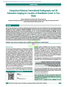
a b s t r a c t We evaluated two treatment concepts for the rehabilitation of moderate atrophic maxilla with dental implants (all-on-four and all-on-six) and the effect of framework material on the stress distribution of implant-support system. A three-dimensional finite element model based on a prototype was built to simulate an entirely edentulous maxilla with moderate sinus pneumatization that was rehabilitated with a full-arch fixed dental prosthesis. Four standard implants were positioned according to the all-on-four concept and four standard implants and two short implants were placed according to the all-on-six concept. Three framework materials were evaluated: cobalt-chrome (CoCr), titanium (Ti) and zirconia (Zr), totalizing six groups. A unilateral oblique force of 150 N was applied to the posterior teeth. The von Mises (σVM), maximum (σmax) and minimum (σmin) principal stress and displacements were obtained. All-on-six showed smaller σmin, σVM and σmax values on the cortical bone, implants and trabecular bone, respectively. All-on-four exhibited higher displacement levels. Ti presented the highest stress values on the cortical bone, implants, abutments, prosthetic screws and displacement levels. In conclusion, the all-on-six approach and framework stiffer materials showed the most favorable biomechanical behavior. However, the stress values did not exceed the bone resistance limits for both treatment concepts. © 2016 Elsevier B.V. All rights reserved.
1. Introduction The edentulous maxilla's anatomic characteristics make rehabilitation of atrophic jaws with dental implants challenging. Its complex, three-dimensional reabsorption process involves vertical and/or horizontal reabsorption of the alveolar ridge and sinus pneumatization [1]. In addition, stretched nasal cavities [2], resorption of the posterior region [3], and low bone quality and quantity [4] are often observed. The posterior bone reabsorption restricts the use of dental implants and often results in the use of long cantilevered prostheses [5,6], or sinus-grafting procedures [7]. In the presence of a cantilever, implant overstress can be observed [5,6], which increases the implant failure risk and biomechanical complications. Sinus-grafting surgery has limitations, including multiple surgical procedures, patient morbidity, a higher risk of complications, a longer treatment period, higher costs and low patient acceptability [8,9]. The all-on-four concept was introduced to address these problems [10]. This treatment concept enables the rehabilitation of a fully ⁎ Corresponding author at: Av. Limeira, 901, Piracicaba, Sao Paulo 13414-903, Brazil. E-mail addresses:
[email protected],
[email protected] (V.A.R. Barão).
http://dx.doi.org/10.1016/j.msec.2016.07.059 0928-4931/© 2016 Elsevier B.V. All rights reserved.
edentulous jaw with minimal bone volume, short treatment intervals, lower cost, lower patient morbidity and a better quality of life [7,10, 11]. Four implants are used to rehabilitate fully edentulous jaws with fixed dentures [11]. Two implants are placed axially in the anterior region of the alveolar ridge, and two are distally angled (30° to 45°) in the posterior region. Clinical studies [3,7,10] have shown that the allon-four approach is predictable and has an implant cumulative survival rate of up to 99%. However, prosthetic survival is slightly smaller (up to 95% after 10 years) [12]. Problems such as prosthetic fracture, porcelain crown fracture, abutment loosening, prosthetic screw loosening and factors that lead to prosthesis overloading, such as bruxism or presence of long cantilever may be related to the decrease of prosthetic survival rate in All-on-Four concept [3]. Depending on the positioning of posterior implant and the degree of jaw atrophy, the presence of cantilever may be inevitable which increases the risk of mechanical complications in the prostheses (up to 50%) [3]. Thus, the presence of bone volume in the posterior jaw that allows the insertion of more implants is beneficial to improve prosthetic support and to decrease cantilever length [3]. The use of short implants in the posterior region is also considered a non-invasive alternative to bone grafting procedures and a viable option from a biomechanical point of view because a larger number of implants
716
C.L.B. Bhering et al. / Materials Science and Engineering C 69 (2016) 715–725
can result in a better distribution of force on the implant-support system. Implants of 7.0 and 8.5 mm have shown success rates similar to those of standard-length implants [13]. Although the all-on-six concept appears to induce lower stress compared to the all-on-four concept [14], factors related to the prostheses have not yet been evaluated. The prosthetic framework material plays an important role in stress transmission to the implant-support system and the peri-implant bone region [15]. Titanium and a cobalt-chromium alloy are widely used as prosthetic framework materials due to their biocompatibility, low cost, low density and favorable mechanical properties [16,17]. Zirconia, which improves the esthetic results, has emerged as a prosthetic framework material [18]. However, studies are conflicting regarding the stress transmitted by this material [15, 19]. In addition, little is known about either its strength and stress transmission when subjected to occlusal forces or its biomechanical behavior in situations with a smaller number of implants or in tilted implant situations. In full-arch dental prosthesis, the prosthetic framework can generate more complications when long-span prostheses are used instead of short-span ones [20]. In cross-arch form, the prosthesis is more susceptible to deformation and bending during occlusal forces. Therefore, higher stress and smaller overall survival estimation could be observed in clinical cases planned with long spans [21]. Thus, in long spans cases, especially in cantilever situations, the prosthetic framework is higher requested to maintain the stability of the system than short span cases. It might result in framework material overload and/or higher stresses transmission for implant-support system. Consequently, the prosthetic framework material may play an important role to reduce the biomechanical complications in long-span prosthesis. Therefore, the aims of this study were to evaluate: (1) two alternatives to a bone grafting procedure for the rehabilitation of moderate atrophic maxilla with dental implants: all-on-four (gold standard) and all-on-six (experimental group) concepts; and (2) the effect of the prosthetic framework material on the stress patterns of the implant-support system. The hypotheses tested were as follows: (1) a short implant in the posterior maxillary (all-on-six concept) would result in lower stress to the implants and bone tissue than do long, angled implants (all-onfour concept); and (2) the prosthetic framework material would be a critical factor for stress in the peri-implant region. 2. Materials and methods 2.1. Experimental design A fully edentulous maxilla was fabricated to simulate an atrophic maxilla with moderate sinus pneumatization that would be rehabilitated with a full-arch fixed dental prosthesis according to the all-on-four (F) or all-on-six (S) treatment concepts. Different framework materials, including cobalt-chromium alloy (CoCr), titanium (Ti), and zirconia (Zr) were used. Six three-dimensional (3D) finite element models were created (Table 1).
2.2. Modeling A 3D virtual model of a fully edentulous maxilla was selected from the computed tomography (CT) database of the Renato Archer Information Technology Center (CTI, Campinas, Sao Paulo, Brazil). The anatomic characteristics of the maxilla model were adjusted based on the literature to simulate the treatments concepts being evaluated. The cortical bone was 1 mm thick and the trabecular bone was an internal structure [22]. In the posterior region, the distance between the residual alveolar ridge and the posterior wall of the sinus floor in short implant area was 7.43 mm [1]. The final maxilla dimensions were 17 mm high, 55 mm long and 80 mm wide. Computer-aided design (CAD) images of the implants and prosthetic components were supplied by the manufacturer (Conexao Prosthesis System, Aruja, Sao Paulo, Brazil). Branemark-type implants (EASYGRIP Porous RD, External Hexagon – HE; Conexao Prosthesis System) and mini-abutments (Micro-Unit, HE - 3.75 × 4.0 mm; Conexao Prosthesis System) were then incorporated into the model and positioned according to each simulated clinical condition (Table 1). The locations and characteristics of the dental implants and mini-abutments are shown in Table 1. All structures were modeled using Rhinoceros 5.0 SR12 software (McNeel North America, Seattle, Washington, USA). Using the Selective Laser Sintering technique and a 3D printer (HiQ 2000 3Dsystems, Hemel Hempstead, UK), prototypes of the virtual models were made with nylon with perforations in the implant region for each clinical condition The prototypes were produced to obtain a waxed pattern of the prosthetic frameworks for fixed implant-support dentures with ceramic veneer. The implants were inserted in the prototypes with the help of a manual torque meter (Conexao Prosthesis System). The implants were numbered 1 to 4 (F groups) and 1 to 6 (S groups) (Fig. 1 a, b). After the insertion of implants and mini-abutments, calcinable mini-abutment cylinders were screwed in place, and the prosthetic framework was waxed with standardized dimensions (Fig. 1 c, d). The waxed prosthetic frameworks were manufacture with 14 teeth (central incisor to second molar bilaterally) for the S groups and 12 teeth for the F groups (central incisor to first molar bilaterally). This difference occurred because of the standardization of the implant positioning in the models. The four implants in the anterior maxilla region were positioned in the same place for both models. In the S groups, the presence of a distal short implant eliminated the need for a cantilever. As the F groups had one less implant than the S groups, the waxed prosthetic framework was manufactured up to the first molar to reduce the cantilever length, which could overestimate the stress into these groups. The waxed framework guided the modeling of the prosthetic framework because it presented complex contours and dimensions (anatomical shape). Moreover, it served as a “surgical guide” to verify the correct positioning of the implants in the virtual model according to the previously determined regions (Table 1). The waxed prosthetic framework was scanned (MODELA MDX-20, Roland, Japan), and the images were joined using Meshmixer software
Table 1 Implant location and implant and prosthetic component features of studied groups. Clinical situation
Prosthetic framework material
Group
Implant number
Implant location
Implants positioning
All-on-four (F) (gold standard)
Titanium
F-Ti
4
2 – lateral incisor
Vertical
2 – 2nd premolar
Inclined 45° to the distal
2 – lateral incisor
All-on-six (S) (experimental group)
CoCr Zirconia
F-CoCr F-Zr
Titanium
S-Ti
6
Implant features
Mini-abutment features
References [3,10,14]
HE – 4.0 × 11.5
Straight profile – 4.0 × 4.0
mm HE – 4.0 × 13
mm 30° Angled profile – 4.0 × 4.0
Vertical
mm HE – 4.0 × 11.5
mm Straight profile – 4.0 × 4.0 mm Straight profile – 4.0 × 4.0
CoCr
S-CoCr
2 – 2nd premolar
Vertical
mm HE – 4.0 × 11.5
Zirconia
S-Zr
2 – 2nd molar
Vertical
mm HE – 5.0 × 7.0
mm Straight profile – 4.0 × 4.0
mm
mm
[14]
C.L.B. Bhering et al. / Materials Science and Engineering C 69 (2016) 715–725
717
Fig. 1. Prototypes of the virtual models with the implants and the waxed fixed implant-support prosthetic framework for ceramic veneer: F (a, c) and S (b, d) groups.
(Meshmixer version 10.9.297, Autodesk 2014, Sao Rafael, California, USA). Rhinoceros 5.0 SR12 software was then used to refine the framework contours (Fig. 2). The distance between the prosthetic framework and the maxilla (3.91 mm) and prosthetic framework high (11.11 mm) was constant for all models. The final dimensions of prosthetic framework was the same for all groups, however, F group had 6.96 mm of distal cantilever while S group not presented cantilever. Moreover, due to posterior implants tilting in the F group, different ratios in the straight and angled prosthetic abutments were observed. The implant/abutment ratios were 1.9 for straight abutment and 2.4 for angled abutment. Besides this difference, it represents the real clinical situation which
makes our results more clinical related. The CAD of the prosthetic screws was imported to the software using its original dimensions. 2.3. Prototypes Prototyping can be a useful tool during the fabrication of virtual finite element models, particularly in cases of completely edentulous ridges. The determination of the correct positioning of implants is often hampered by the absence of reference teeth. The incorrect distribution/inclination of implants in the alveolar ridge may result in a misinterpretation of the results. In this study, prototypes were essential to
Fig. 2. Virtual prosthetic framework and implant positioning on a three-dimensional virtual model of the F (a - occlusal view; b - frontal view; c - lateral view) and S (d - occlusal view; e frontal view; f - lateral view) groups. Note the distance of 7.43 mm between the residual alveolar ridge and the posterior wall of the sinus floor (black arrow).
718
C.L.B. Bhering et al. / Materials Science and Engineering C 69 (2016) 715–725
Fig. 3. Finite element mesh for the F (a - frontal view; c - lateral view) and S (b - frontal view; d - lateral view) concepts. Note the number of elements and the accuracy of the mesh around the implant surface (peri-implant region) and in the contact areas of the framework, abutment, implant and cortical bone.
ensure that the anterior implants of both treatment concepts were positioned in the same place in the maxillary model and that the biomechanical behaviors of both concepts could be compared without bias. Therefore, the prototype can be considered an adjunct tool when building 3D virtual models to improving the quality and accuracy of the study. Furthermore, it facilitates the comparison and/or validation of the finite element models with other stress analysis methodologies, such as strain gauges and photoelasticity, because the laboratory models that are obtained will be exact replicas of the virtual models.
2.4. Meshing procedure The 3D models were exported to the HyperMesh 13.0 software (HyperWorks version 13.0, Altair, Troy, Michigan, USA) for mesh
generation, definition of material properties, boundary and loading conditions. Tetrahedral elements with 10 nodes were used for mesh generation. The tetrahedral elements were adjusted for all structures with minimum and maximum sizes (0.15 to 0.7 mm). All regions of stress concentration that were of interest were manually refined (Fig. 3). Manual control is necessary and advantageous because it enables refined meshes in special regions of interest through the selective distribution of elements and sizes [23]. Here, the mesh was extensively refined in all regions of interest to ensure the accuracy of the analysis, resulting in a large number of elements and nodes. The virtual 3D models presented a total of 1,662,843 elements and 2,658,021 nodes (F groups) and 2,472,167 elements and 3,810,275 nodes (S groups) (Fig. 3). All materials were considered isotropic, linearly elastic and homogeneous. The materials properties were: cortical bone (Young's Modulus, E =
Fig. 4. Frontal (a, b) and occlusal (c, d) views of the load application (red lines) for the F (a, c) and S (b, d) groups. Note the rigid fixation restriction in the upper maxilla - gray lines (a, b). (For interpretation of the references to color in this figure legend, the reader is referred to the web version of this article.)
C.L.B. Bhering et al. / Materials Science and Engineering C 69 (2016) 715–725
719
Fig. 5. Stress values (MPa) in maximum principal stress (σmax), minimum principal stress (σmin) and von Mises stress (σVM) for the cortical bone (a), trabecular bone (b), implants (c), abutments (d), prosthetic screws (e), and prosthetic framework (f) in all groups.
13.7 GPa, and Poisson Ratio, μ = 0.3) [15], trabecular bone (E = 1.37 GPa, μ = 0.3) [15,22], implants (E = 110 GPa, μ = 0.3) [15], screws (E = 110 GPa, μ = 0.28) [15], mini-abutment (E = 110 GPa, μ = 0.28) [15], CoCr framework (E = 218 GPa, μ = 0.33 and Yield Stress 500– 635 MPa) [15], Ti framework (E = 110 GPa, μ = 0.28 and Yield Stress 795–875 MPa) [15], Zr framework (E = 205 GPa, μ = 0.22) [24]. 2.5. Boundary and loading conditions The models were subjected to a rigid fixation restriction in the upper maxilla to prevent displacement in the x, y and z axes (Fig. 4 a, b). The implants were considered fully osseointegrated to the peri-implant bone. The mini-abutment/implant interface was also considered a bonded contact. The prosthetic framework and mini-abutment interface were considered with a 0.3 frictional coefficient [25] to better assess the prosthetic framework displacement. The preload was calculated as established by Adams and Abraham [26] according to the formula F = T/(K*D*1.2), where F = axial force in the fastener, T = applied torque, K = friction factor and D = major diameter of the fastener. Torque (T) was considered as 100 N.mm
(10 N.cm), friction factor (K) was 0.3 (established by Adams & Abraham (1999) [26] for nonplated/nonlubricated connection), diameter of screw (D) was 2 mm, and 1.2 was used to account flexibility of the bolt shank, which springs back a small amount after the torque is applied [26]. Thus, we observed that the application of a 10-N.cm torque generated an axial force (F) of 138.9 N on the prosthetics screws. For the finite element analysis (FEA), an oblique load of 150 N [14] with a 30° inclination in the linguo-buccal direction was applied unilaterally on the posterior teeth of each framework in the evaluated groups. For the F groups, the load was divided among the first premolar, second premolar and first molar, while for the S groups, the load was divided among the first premolar, second premolar, first molar and second molar (Fig. 4 c, d). The load was divided equally on the posterior teeth to compensate for the difference in the number of teeth in the frameworks of the groups. 2.6. Stress analysis The FEA was performed using Optistruct 13.0 software, and the results were analyzed in HyperView 13.0 software. von Mises stress
Fig. 6. Maximum principal stress (σmax) distribution (in MPa) in the cortical bone in all groups.
720
C.L.B. Bhering et al. / Materials Science and Engineering C 69 (2016) 715–725
Fig. 7. Minimum principal stress (σmin) distribution (in MPa) in the cortical bone in all groups.
(σVM) was obtained for metallic materials due the ductile nature, and maximum principal stress (σmax) and minimum principal stress (σmin) were obtained for non-ductile materials. The σmax and σVM stress were obtained for all framework materials due to the heterogeneity of materials properties. A displacement analysis was also performed. 3. Results The stress peaks values in each structure of all groups are shown in Fig. 5. 3.1. Cortical bone Regardless of the treatment concept, the Ti framework showed the highest σmax (F = 19.9 MPa; S = 27.4 MPa) and σmin (F = −47.7 MPa; S = −35.2 MPa) values, while the CoCr and Zr frameworks showed similar values. The S groups showed an σmax increase of 21% and an σmin decrease of 25% compared to the F groups (Fig. 5a). In general, all materials showed similar distribution patterns of σmax over cortical bone (Fig. 6). Regarding to the treatment concept, S groups distributed the stress to a greater area (Fig. 6). For the F groups, the
highest concentration values were observed in the peri-implant region, primarily around implant #1. The S groups showed the same behavior; however, the highest concentration values were observed on implant #6 (load application site), and the stress extended over all implants until the region beyond the midline (implant #1). Regarding σmin, for all materials, the highest concentration values were observed in the disto-buccal peri-implant region of implant #4 (F groups) and implants #6 and #2 (S groups) (Fig. 7). 3.2. Trabecular bone All materials showed similar σmax (F = 5.7 MPa; S = 5.1 MPa) and σmin (F = −4.2 MPa; S = −4.7 MPa) values. However, the F groups exhibited a moderate σmax increase of 10.5% and an σmin decrease of 10.6% compared to the S groups (Fig. 5b). A similar σmax distribution pattern was observed for all groups (Fig. 8). The highest stress values were found on the buccal side of the maxilla in the cortical/trabecular bone interface of the implant #4 site (primarily in the cervical and apical regions). The same behavior was noted for the S concept, with additional stress at the implant #6 site. The σmin distribution was similar to that of σmax (Fig. 9). The vector field demonstrated this similarity of stress
Fig. 8. Maximum principal stress (σmax) distribution (in MPa) in the trabecular bone in all groups.
C.L.B. Bhering et al. / Materials Science and Engineering C 69 (2016) 715–725
721
Fig. 9. Minimum principal stress (σmin) distribution (in MPa) in the trabecular bone in all groups.
concentrations between σmax and σmin in the trabecular bone (data not shown).
3.3. Implants Regardless of the number of implants, Ti groups showed the highest σVM values (F = 78 MPa; S = 64.3 MPa), while the σVM values were similar in the CoCr and Zr groups. The S treatment concept showed a decreased of 19% in the stress value over the implants compared to the F concept (Fig. 5c). The highest σVM values were concentrated primarily in the implant/cortical bone interface (Fig. 10). The highest stress concentrations were shown around the neck of the implant and in the first three threads for tilted implants (F groups) and implants #4 and #6 (S groups).
3.4. Abutments The use of a Ti framework resulted in an σVM increase of 7.4% in the F group abutments. For the S groups, all materials showed similar values. In the F groups, the σVM value increased by 58.7% compared to the S groups (Fig. 5d). The highest σVM values were noted in the abutment platform in all cases (Fig. 11). However, in the S groups, the values decreased from right to left from the load application point to the contralateral side.
3.5. Prosthetic screws Regardless of the implant number, Ti showed the highest σVM values (F = 132.0 MPa and S = 177.5 MPa), while CoCr and Zr had similar values. The σVM value decreased by 27.7% over the prosthetic screws in the F groups compared to the S groups (Fig. 5e). The σVM was concentrated primarily on the neck of the screw, as expected, for all groups (Fig. 12). The highest stress values were observed on the loaded side.
3.6. Prosthetic framework The stress level increased by 11.7% in the F groups compared to the S groups when CoCr or Ti was used as the prosthetic framework material (σVM value). When Zr was used as the prosthetic framework material, the stress level decreased by 18% in the F groups compared to the S groups (σmax value) (Fig. 5f). The stress values comparison among the different framework materials is limited due to their different nature (ductile and ceramic). The σmax and σVM stress were obtained for all materials only to evaluate the overall behavior. In general, the highest stress values were noted for CoCr, followed by Zr and Ti. The stress distribution pattern was similar for all groups (Fig. 13). The stress concentrations were mainly in the abutment seat base, the connection bar between the teeth and the middle line of the framework (between the central incisors). The highest (σVM) values were found in the abutment seat base of the first left molar (F groups) and first left
Fig. 10. von Mises stress (σVM) distribution (in MPa) in implants in all groups.
722
C.L.B. Bhering et al. / Materials Science and Engineering C 69 (2016) 715–725
Fig. 11. von Mises Stress (σVM) distribution (in MPa) in abutments in all groups.
premolar and second left molar (S groups), which are the locations of loading application. 3.7. Model displacement The Ti groups (F = 46 μm; S = 37 μm) had higher displacement levels, while the Zr and CoCr groups showed equal values (Fig. 14). The F concept led to a 16.4% increase in the displacement levels of the implant-support system. The model displacement trend coincided with the direction of the load (Fig. 15). In addition, bending of the framework in the anterior region (midline) was observed. 4. Discussion 4.1. Treatment concept influence This study compared the mechanical behavior of two alternative treatments (the F and S concepts) to a bone grafting procedure for the rehabilitation of moderate atrophic maxilla with dental implants. The first hypothesis tested, which proposed that short implants in the posterior maxillary (S concept) would result in lower stress to the implants and bone tissue than would long, angled implants (F concept), was partially accepted. The S treatment showed lower σVM (19%) and σmin (25%) values on the implants and cortical bone, respectively. These findings corroborate with previous studies that compared these alternative
treatment concepts for the mandible [27] and maxilla [14]. The presence of a greater number of implants in the S concept allows better transmission of force to the implants and supporting tissues, which may explain our results. The same behavior was noted for trabecular bone, which showed a slight decrease in the σmax (10.5%) value in the S group. The stress reduction caused by the addition of implants in the posterior region was in accordance with an in vivo study [28]. However, considering the σmax in the cortical bone, the S concept showed higher values than the F concept. The smaller displacement values observed in the S groups may be the driving force toward such result. The prosthetic framework loading created energy on the system that resulted in framework deformation and bending, which were distributed over the entire framework length and displaced the implants [28]. One study found that when there was a large amount of deformation next to the load application point, higher stress levels were observed around the supporting implants and there was a reduction of the energy and stress transmitted to the other implants [28]. These findings corroborate with the results of this study. The presence of a distal support in the S groups (implant #6) resulted in a higher resistance to displacement of the assembly, and therefore, smaller displacements and higher stress values (σmax) were observed on the load application point compared to the F groups. To the authors' best knowledge, no study has evaluated the influence of the treatment concept and framework materials for full-arch maxillary prostheses in terms of σmax, σmin, σVM and displacement levels.
Fig. 12. von Mises stress (σVM) distribution (in MPa) on the prosthetics screws in all groups.
C.L.B. Bhering et al. / Materials Science and Engineering C 69 (2016) 715–725
723
Fig. 13. von Mises stress (σVM) (for CoCr and Ti) and maximum principal stress (σmax) (for Zr) distribution (in MPa) on the prosthetic frameworks.
Ozdemir Dogan et al., [27] concluded that the S concept shows better results than the F concept in the mandible; however, those authors only evaluated the σmin for bone tissue with a Ti framework. Almeida et al., [14] observed lower σmax and σmin values with the S concept than with the F concept using a Ti framework. In addition, their models were simplified (i.e., an absence of anatomical framework and/or implant threads). According to physiological limits (ultimate bone strength), overloading in cortical bone occurs when the σmin exceeds 170 to 190 MPa and the σmax exceeds 100 to 130 MPa; in trabecular bone, this occurs when either σmin or σmax exceeds 5 MPa [6,29,30]. Based on these limits, the values observed in both treatment concepts were below than those considered pathologic to bone tissue. Regarding stress distribution patterns, both treatment concepts showed similar results. In all cases, the highest stress concentration points coincided with the location of the load application, as expected. The only difference was that for the S groups, the stress was distributed over a greater area, extending from implant #6 to implant #1 (cortical bone, trabecular bone, implants, and abutments) with a slight decrease in the concentration peaks, from the load application point. The similar mechanical behavior of the two treatment concepts may be related to similar clinical success rates of full-arch fixed dental prostheses supported by four or six implants [22]. Although the F concept is an effective approach for edentulous maxilla and has a high short-term success rate [7], the use of short implants appears to be another viable alternative for the posterior maxilla. The favorable biomechanical aspects of the six-implant design observed in this study, such as lower stress on the implants, abutments, and bone supports and a lower displacement system, may be of interest in clinical practice. The promising results of the S concept suggested that in cases of biomechanical risk (e.g., bruxism, low-quality bone), a larger number of implants may be necessary [22]. Moreover, the use of short implants in the S concept eliminates the need for a cantilever. It is significant as the use of a cantilever should be avoided or minimized because its presence greatly increases stress on the distal implant [22]. This is an important factor in possible clinical failures in implant dentistry [5,6]. It is necessary to highlight that the predictability of short implants is related to the implant design, insertion protocol [27], occlusion concept [31], residual bone height and bone volume [32], and patient hygiene.
fractures or mechanical complications would not occur under such conditions. Materials with high elastic moduli are more resistant to bending and deformation and, therefore, have high stress values. These results are in line with previous studies [15,36,37]. Despite of the higher stress concentration in the prosthetic framework, stiffer materials transmitted lower stress for the other system components. According to Sertgoz et al. [37], the use of more rigid materials for the prosthetic framework may be recommended to prevent failure of implant-support system. This correlates with the lower stress observed in the cortical bone, implants, abutments and screws and the lower displacement level of the implant-support system when using frameworks made of Zr and CoCr. Previous studies also showed that more rigid materials result in lower stress values on the bone [15,28], implants [38] and retaining screws [15,37]. Therefore, the second hypothesis, which was that the elasticity modulus of the prosthetic framework material influences the stress on the peri-implant region, was accepted. Regarding the stress distribution pattern in the prosthetic framework, the stress concentration in the abutment seat base most likely occurred because of the contact interface between the framework and the abutment and the preload applied to the retaining screws. The concentrations in the bar connectors (between the teeth) and in the middle line are associated with changes in the framework geometry in this region. The reduction in material thickness makes such regions more susceptible to a greater stress concentration. Fractures in the anterior region have been described as a common complication in some clinical studies and have been attributed to the absence of a metallic framework in provisional prosthesis [7]. However, the outcome of this study indicates that the stress concentration in the anterior region also occurs when either a metal or ceramic framework is used. The bending and torsion of the framework in the middle line may explain these results.
4.2. Prosthetic framework material influence In the present study, the prosthetic framework material was influential on the stress and displacement of the implant-support system. In general, stiffer materials (i.e., Zr and CoCr) showed higher stress values (σmax and σVM) in the prosthetic framework than did soft materials (i.e., Ti). However, all stress values were within the tensile strength limit for all materials evaluated: CoCr (552 to 1034 MPa) [33], Ti (860 to 965 MPa) [34] and Zr (900 to 1200 MPa) [35]. This indicates that
Fig. 14. Displacement values (in μm) in all groups.
724
C.L.B. Bhering et al. / Materials Science and Engineering C 69 (2016) 715–725
Fig. 15. Maps of displacement levels (μm) in all groups. The meshed black framework contour represents the initial position (before load) while the bulk colored framework contour represents the maximum displacement after load.
The Ti framework with the F concept was the least successful model tested. The low elasticity modulus of Ti and the absence of a distal support for the framework in the F groups support this outcome. These findings support those of Benzing et al. [28] that the material properties (elasticity modulus), number of implants, implant distribution in the jaw, and distal support are determining factors for displacement and stress levels in the implant-support system. 4.3. Limitations and future work All materials were considered homogeneous, isotropic, and linearly elastic, and 100% contact among the bone, implant and implant/abutment interface was assumed. Although these assumptions do not occur in clinical practice, they are common in FEA studies due to the challenges in establishing the properties of living tissues and the osseointegration level in bone-implant surfaces. These limitations are inherent in biologic simulations [14]. Bone is a biologic complex structure without a defined behavior pattern; its characteristics differ among individuals, and the mechanical properties and time effect are not clear [14,22]. The present assumptions are consistent with other FEA studies [14,22,27,39]. In addition, these assumptions would not interfere with the qualitative and comparative results because they were equal for all models. The same friction coefficient was used for all materials so that the mechanical behavior of the groups would be compared without the bias of different coefficient values. Different coefficient would be another variable in the studied models, which may affect the interpretation of results. In addition, knowledge about the friction coefficient between different prosthetic framework material (CoCr, Zr and Ti) and mini-abutments (Ti) is still limited. Another limitation was the absence of other treatment concepts for the rehabilitation of the maxilla, such as zygomatic implants or bone-grafting procedures followed by the placement of long implants. Moreover, in this study only unilateral static load was applied. Cyclic loads such as those occurring during chewing movements could result in different behavior for Zr frameworks, given the fragile nature of such material. It suggests that CoCr frameworks can be the most suitable material for manufacture full-arch fixed framework. We apply only unilateral load to check the biomechanical behavior of the implant-support system in a critical situation. It simulates a tendency of prosthetic framework tilting and bending as observed in previous studies [40,41]. During the masticatory movements in the working side (load application side) the prosthesis
moves down while in the balancing side it moves up [40]. This pattern of prosthesis movement makes all the implant-support system being tested in a critical situation. Moreover, in the chewing initial phase, the food is placed on one side of the prosthesis (working side) and no occlusal contact occurs in the contralateral side (balancing side), so the unilateral load is clinically relevant [40]. Further studies simulating all treatment alternatives for atrophic maxilla that include dynamic forces that occur during chewing and consider the anisotropic and regenerative properties of bone are needed. Furthermore, longitudinal clinical follow-up and randomized clinical trials are necessary to confirm and validate the relevance of these findings in clinical practice. 5. Conclusions Based on the study results, it is possible to conclude that: • The all-on-six treatment concept showed the most favorable biomechanical behavior and can be considered a viable alternative for moderate atrophic maxilla rehabilitation. • Stiffer materials (CoCr and Zr) have the most favorable biomechanical behavior and decrease the stress levels for bone, implants, screws, abutments and displacement magnitude. • The use of titanium as a prosthetic framework material and the all-onfour treatment concept exhibited the worst biomechanical behavior. • The stress values did not exceed the bone resistance limits for both treatment concepts.
Declaration of interest The authors report no conflicts of interest. Acknowledgments This study was supported by the Sao Paulo Research Foundation (FAPESP grant number 2013/22232-0) and the Coordination for the Improvement of Higher Education Personnel (CAPES grant number 33003033008P8). The authors would like to thank Conexao (Conexao Prosthesis System) for providing the CAD models used in this study.
C.L.B. Bhering et al. / Materials Science and Engineering C 69 (2016) 715–725
References [1] M. Chiapasco, M. Zaniboni, J. Oral Maxillofac. Surg. 67 (2009) 867–871. [2] D. Penarrocha-Oltra, E. Candel-Marti, J. Ata-Ali, M. Penarrocha-Diago, J. Oral Implantol., 39 (2013) 625–632. [3] P. Malo, M. Nobre, A. Lopes, Eur. J. Oral Implantol. 4 (2011) 227–243. [4] U. Lekholm, G. Zarb, Patient selection and preparation, in: P.I. Branemark, G.A. Zarb, T. Albrektsson (Eds.), Tissue-integrated Prostheses: Osseointegration in Clinical Dentistry, Quintessence, Chicago 1985, pp. 199–209. [5] A.O. Malhotra, T.V. Padmanabhan, K. Mohamed, S. Natarajan, U. Elavia, Aust. Dent. J. 57 (2012) 440–445. [6] L. Baggi, S. Pastore, M. Di Girolamo, G. Vairo, J. Prosthet. Dent. 109 (2013) 9–21. [7] S.B. Patzelt, O. Bahat, M.A. Reynolds, J.R. Strub, Clin. Implant. Dent. Relat. Res. 16 (2014) 836–855. [8] D. Schwartz-Arad, R. Herzberg, E. Dolev, J. Periodontol. 75 (2004) 511–516. [9] C.P. Cidade, M.J. Pimentel, R.C. Amaral, M.A. Nobilo, J.R. Barbosa, Braz. Oral Res. 28 (2014). [10] P. Malo, B. Rangert, M. Nobre, Clin. Implant. Dent. Relat. Res. 7 (Suppl. 1) (2005) S88–S94. [11] P. Malo, M. de Araujo Nobre, A. Lopes, J. Prosthet. Dent. 97 (2007) S26–S34. [12] G. Heydecke, M. Zwahlen, A. Nicol, D. Nisand, M. Payer, F. Renouard, P. Grohmann, S. Muhlemann, T. Joda, Clin. Oral Implants Res. 23 (Suppl. 6) (2012) 217–228. [13] P. Malo, M. de Araujo Nobre, B. Rangert, Clin. Implant. Dent. Relat. Res. 9 (2007) 15–21. [14] E.O. Almeida, E.P. Rocha, A.C. Freitas Junior, R.B. Anchieta, R. Poveda, N. Gupta, P.G. Coelho, Clin. Implant. Dent. Relat. Res. 17 (Suppl. 1) (2015) e332–e342. [15] A. Bacchi, R.L. Consani, M.F. Mesquita, M.B. Dos Santos, Acta Odontol. Scand. (2013). [16] M. Hulterstrom, U. Nilsson, Int. J. Oral Maxillofac. Implants 6 (1991) 475–480. [17] I. Watanabe, J.H. Watkins, H. Nakajima, M. Atsuta, T. Okabe, J. Dent. Res. 76 (1997) 773–779. [18] J. Abduo, K. Lyons, J. Prosthodont. Res 56 (2012) 102–109. [19] J. Abduo, M. Swain, Int. J. Oral Maxillofac. Implants 27 (2012) 529–536. [20] W. Chee, S. Jivraj, Br. Dent. J. 201 (2006) 501–507. [21] H. De Backer, G. Van Maele, N. De Moor, L. Van den Berghe, Int. J. Prosthodont. 21 (2008) 75–85. [22] G.C. Silva, J.A. Mendonca, L.R. Lopes, J. Landre Jr., Int. J. Oral Maxillofac. Implants 25 (2010) 239–246.
725
[23] C.J. Soares, V. Antheunis, A.D.C.M. Valdivia, A.A. Bicalho, C. Veríssimo, B.D.C.F. Barreto, M.G. Roscoe, Finite element analysis in dentistry - improving the quality of oral health care, in: D.D. Moratal (Ed.), Finite Element Analysis - From Biomedical Applications to Industrial Developments, InTech 2012, pp. 25–56. [24] P.C. Lazari, B.S. Sotto-Maior, E.P. Rocha, G. de Villa Camargos, A.A. Del Bel Cury, J. Prosthet. Dent. 112 (2014) 857–863. [25] M.B. Ferreira, V.A. Barao, J.A. Delben, L.P. Faverani, A.C. Hipolito, W.G. Assuncao, Mater. Sci. Eng. C Mater. Biol. Appl. 38 (2014) 306–314. [26] V. Adams, A. Askenazi, Modeling assemblies and weldments: modeling jointed interfaces, in: O. Press (Ed.), Building Better Products with Finite Element Analysis 1999, pp. 379–409. [27] D. Ozdemir Dogan, N.T. Polat, S. Polat, E. Seker, E.B. Gul, Clin. Implant. Dent. Relat. Res. 16 (2014) 501–510. [28] U.R. Benzing, H. Gall, H. Weber, Int. J. Oral Maxillofac. Implants 10 (1995) 188–198. [29] D.T. Reilly, A.H. Burstein, J. Biomech. 8 (1975) 393–405. [30] R. Martin, D. Burr, N. Sharkey, Skeletal Tissue Mechanics, Springer, New York, 1998. [31] I. Hasan, C. Bourauel, T. Mundt, F. Heinemann, ISRN Dent. (2013) 424592. [32] S. Corbella, S. Taschieri, M. Del Fabbro, Clin. Implant. Dent. Relat. Res. 17 (2015) 120–132. [33] M. Sevimay, F. Turhan, M.A. Kilicarslan, G. Eskitascioglu, J. Prosthet. Dent. 93 (2005) 227–234. [34] M. Niinomi, Mater. Sci. Eng. A 243 (1998) 231–236. [35] P. Christel, A. Meunier, M. Heller, J.P. Torre, C.N. Peille, J. Biomed. Mater. Res. 23 (1989) 45–61. [36] A. Bacchi, R.L. Consani, M.F. Mesquita, M.B. dos Santos, J. Oral, Science 55 (2013) 239–244. [37] A. Sertgoz, Int. J. Prosthodont. 10 (1997) 19–27. [38] R.T. Abreu, A.O. Spazzin, P.Y. Noritomi, R.L. Consani, M.F. Mesquita, J. Prosthodont. 19 (2010) 425–431. [39] M.B. Ferreira, V.A. Barao, L.P. Faverani, A.C. Hipolito, W.G. Assuncao, Mater. Sci. Eng. C Mater. Biol. Appl. 35 (2014) 92–99. [40] V.A. Barao, J.A. Delben, J. Lima, T. Cabral, W.G. Assuncao, J. Biomech. 46 (2013) 1312–1320. [41] M. Daas, G. Dubois, A.S. Bonnet, P. Lipinski, C. Rignon-Bret, Med. Eng. Phys. 30 (2008) 218–225.