Journal of Space Technology, Vol 1, No. 1, July 2012
Comparison of Adaptive Beamforming Algorithms Robust Against Directional of Arrival Mismatch Zafar Ullah Khan, A. Naveed, I. M. Qureshi, and Fawad Zaman presumed and actual signal direction. Efforts are in progress to develop robust algorithms for such mismatches. Diagonal loading [5] is a popular technique robust against direction of arrival mismatch but has no suitable way to find the diagonal loading factor. Another attractive approach is robust adaptive beamforming using worst case performance optimization [6]. But its performance is quite close to the simple algorithm known as diagonal loading of the sample matrix inversion (LSMI) algorithm. In [7] a technique is presented which makes GSC robust against direction of arrival (DOA) mismatch by modifying its blocking matrix in order to broad the sharp nulls using the method discussed in [8]. This paper presents the performance comparison of different robust adaptive beamforming algorithms and utilizes Convex optimization as an alternative and efficient method to solve the null broadening problem for robust GSC [7], [8].
Abstract-The conventional adaptive beamformers face the problem of performance degradation in the presence of desired signal in the training data snapshots if there is a small mismatch between the presumed and the actual signal direction. In case of such mismatch, these beamformers generate the main beam in the presumed direction of desired signal and the actual signal with mismatched direction is considered as the interference, so the desired signal cancellation appears in this situation. This paper presents the effect of direction of arrival mismatch on traditional beamformers like minimum variance distortionless response (MVDR) and generalized sidelobe canceller (GSC). Furthermore, the performance comparison of different adaptive Beaforming algorithms which are robust against direction of arrival mismatch has also been done. These algorithms include worst case performance optimization beamformer for direction of arrival mismatch and generalized sidelobe canceller with modified blocking matrix. Simulation results show that the GSC with modified blocking matrix has better performance as compare to the worst case performance optimization beamformer for direction of arrival mismatch.
II. Index Terms— Adaptive beamforming, Minimum variance distortionless response (MVDR) beamformer, Generalized sidelobe canceller (GSC).
BACKGROUND
A. MVDR Beamformer This beamformer minimizes the output power and maintains the distortionless response in the desired signal direction. Let
I. INTRODUCTION
a (θ s ) be the steering vector in the desired signal direction and R is the received signal covariance matrix, the
W
HEN exact knowledge of direction of arrival of desired signal and interferences is available, array signal processing with progressive phase can be used to generate the main beam along the desired signal direction and nulls in the direction of interferences [1]. On the other hand, adaptive beamforming, which has its applications in the field of radar, sonar, and wireless communications [2]-[4], requires only the desired signal direction. Minimum variance distortionless response (MVDR), sample matrix inversion (S MI), linearly constrained minimum variance (LCMV), and generalized sidelobe canceller (GSC) are the popular adaptive beamformers. These beamformers face the problem of performance degradation when the desired signal appears in the data snapshots and there is a mismatch between the
optimization problem and its solution in terms of beamformer weight vector
wMV are given in (1) and (2) respectively.
min wH Rw Subject to w
w H a (θ s ) ! 1
(1) "1
wMV !
Manuscript received May 29, 2012. Received after re-formatting June 1, 2012 Received after modification as per reviewer’s comments July 12, 2012. Z. U. Khan and F. Zaman are with Department of Electronic Engineering, Faculty of Engineering and Technology, International Islamic University Islamabad, Pakistan.: Phone:+923065482263; (e-mail:
[email protected] ;
[email protected]). A. Naveed is with School of Engineering & Applied Sciences (SEAS) Isra University, Islamabad Campus, Pakistan, (e-mail:
[email protected]). I. M. Qureshi is with Department of Electrical Engineering Air University Islamabad, Pakistan, (e-mail:
[email protected]).
28
R a (θ s ) a (θ s ) R "1a (θ s ) H
(2)
Comparison of Adaptive Beamforming Algorithms Robust Against Directional of Arrival Mismatch
./0123456452637)82+(9-
B. SMI Beamformer This beamformer minimizes the array output signal to
Rs be the signal
interference-plus-noise ratio (SINR). Let
covariance matrix, the optimization problem for this beamformer is stated as:
min wH Rw Subject to w
w Rs w ! 1 H
./0123456452637)82+(9-
where
P{} # is
!'# !&# !%# !$# !"##
!$#
!%#
!&#
!'#
# ()* +,-
'#
&#
%#
$#
"##
!$#
!%#
!&#
!'#
# ()* +:-
'#
&#
%#
$#
"##
(3)
The solution to this optimization problem as given in [9] is
wopt ! P{R "1 Rs }
#
the
Eigen
vector
corresponding to the maximal Eigen value and wopt is the weight vector. C.Generalized Sidelobe Canceller (GSC) GSC consists of two branches as shown in fig. 1. The upper branch with weight vector wq is quiescent beamformer. The
'# # !'# !&# !%# !$# !"##
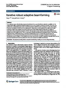
Fig. 2. . (a) MVDR beamformer output without mismatch; desired signal is at 0°. The interferences are at 30° and 60°. (b) Output of MVDR beamformer with mismatch when presumed signal is at 0° while its actual direction is along 3°. The interferences are same as in (a).
vector wq preserves the desired signal in the upper branch. The lower branch is sidelobe cancelling branch which consists of blocking matrix
same direction. Fig. 2(b) shows performance degradation of this beamformer when actual signal direction is at 3°and presumed direction is along 0°, i.e. for a mismatch of 3°.
B and adaptive weight vector wa .
It can be found from literature that wq
! C (C H C )"1 f ,
B ! null{C H } , where C is the constraint matrix containing steering vectors corresponding to each constraint and f is gain
B. Performance of SMI Beamformer Fig. 3(a) and 3(b) show the performance of SMI beamformer without and with mismatch respectively.
vector containing gains corresponding to the constraints.
C.Performance of Generalized Sidelobe Canceller (GSC) The performance of GSC without and with mismatch has been shown in fig. 4(a) and 4(b) respectively.
The optimized adaptive weight vector wa , in the lower branch, denoted by wao is given below in (4).
wao ! ( B H RB) "1 B H Rwq
(4)
In this section two robust beamforming algorithms i.e. worst case performance optimization (WCO) beamformer and robust GSC for direction of arrival mismatch are being discussed.
wq
'
'
x(n)
B
IV. ROBUST ADAPTIVE BEAMFORMERS
wa
A. Worst Case Performance Optimization (WCO) Beamformer Assume that $ is the error matrix in Rs due to mismatch in desired signal direction. Let $ be bounded by some known
y(n)
"
% i.e.
positive constant
$ & % . Where
#
denotes
Frobenius norm of a matrix. In [9], the constraint for SINR maximization has been modified for the beamformer robustness against direction of arrival mismatch as given below
Fig. 1. Generalized Sidelobe Canceller
III. DOA MISMATCH EFFECT ON TRADITIONAL
w H ( Rs ' $( w ) 1 For all $ & %
BEAMFORMERS
So SMI optimization problem becomes as
In order to observe the effect of direction of arrival mismatch on traditional beamformers, we have considered one desired signal with presumed direction along 0° and two interferences at 30° and 60°respectively.
min wH Rw Subject to w
w ( Rs ' $(w ) 1 , for all $ & % H
(5)
For the worst case performance, $ can be found by solving the following optimization problem
A. Performance of MVDR Beamformer Fig. 2(a) shows the performance of MVDR beamformer without mismatch i.e. presumed and actual signal are in the 29
Comparison of Adaptive Beamforming Algorithms Robust Against Directional of Arrival Mismatch
min wH ( Rs ' $(w Subject to $ & % .
V. SIMULATION RESULTS FOR ROBUST ADAPTIVE BEAMFORMERS
$
For this problem $ comes out to be [9]
$ ! "%
ww w
By putting the value of becomes as
A uniform linear array of 16 antenna elements has been used with inter element spacing /2. One desired signal with presumed direction along 0° and two interferences at 30° and 60° respectively have been used for simulation in MATLAB. All the results have been averaged over 500 snapshots.
H
(6)
2
$ , the optimization problem (5)
A. Performance of Worst Case Optimization Beamformer Fig. 3(b) shows the performance of SMI beamformer for comparison with WCO for the 3° mismatch i.e. the actual signal direction is along 3°. Fig. 3(c) shows the performance of WCO beamformer for the same situation as in fig. 3(b). For fig. 3(c), we have used % ! 123 and , ! 50.
min wH Rw Subject to w H ( Rs " %*( w ! 1 w
The optimum weight vector for the robust beamformer comes out to be
wrob ! P{R "1 ( Rs " %I } To overcome other array imperfections, similar mismatch
$+
$+ & , . The robust
;.?@23456452637)82+(9- ;.