INTERNATIONAL JOURNAL OF ELECTRONICS; MECHANICAL and MECHATRONICS ENGINEERING Vol.3 Num.1 pp.(427-436)
COMPARISON OF REAL AND COMPLEX-VALUED VERSIONS OF WAVELET TRANSFORM, CURVELET TRANSFORM AND RIDGELET TRANSFORM FOR MEDICAL IMAGE DENOISING
Huseyin YASAR1, Murat CEYLAN2, Ayse Elif OZTURK3 1
2
Ministry of Health, Ankara, TURKEY, E-mail:
[email protected]
Selcuk University, Department of Electrical and Electronics Engineering, 42075, Konya, TURKEY, E-mail:
[email protected] 3
Istanbul Aydin University, Electronics Technology, 34295, Kucukcekmece, Istanbul, TURKEY, Corresponding Author’s E-mail:
[email protected]
Abstract- In this study; medical images were denoising with multiresolution analyses using real-valued wavelet transform (RVWT), complex-valued wavelet transform (CVWT), ridgelet transform (RT), real-valued first-generation curvelet transform (RVFG CT), real-valued second-generation curvelet transform (RVSG CT), complex-valued second-generation curvelet transform (CVSG CT) and results are compared. First and second-generation curvelet transformations are used for realvalued curvelet transform as two techniques. For the evaluation of the proposed system, we used 32 lung CT images. These images include 10 images with benign nodules and 22 images with malign nodules. Different types of noise like the Random noise, Gaussian noise and Salt & Pepper noise were added to these images and they are removed separately. The performances of used transforms are compared using Peak Signal to Noise Ratio (PSNR) parameter. Obtained results showed that complex-valued wavelet transform are suited for removal of random noise and Gaussian noise. In case of Gaussian noise in images, PSNRs of first generation curvelet transform and complex-valued wavelet transform are around 33 dB. The ridgelet transform provides high PSNR value (30.4dB) for denoising of salt & pepper noise in images.
Key Words: Wavelet transform, curvelet transform, ridgelet transform, denoising 1. INTRODUCTION Image processing is an engineering discipline that has been studied extensively and also contains obtaining new images by analyzing the various images. The importance of image processing, especially after digital image recording‘s being widespread, has been increasing day by day. Image processing techniques are used a wide variety of fields like face / fingerprint identification security systems, electromagnetic radar systems, medical systems, geology and astronomy research, mapping and control systems. Fourier analysis which is used for obtaining the information about frequency of image is the basic argument of image processing. Since it is unknown that which or when signals are active, some problems can be occur while implementing the process conversely to unstable frequency valued signals. On the other hand, there
is no problem with the signals have time-invarient frequency value. Since Fourier analysis is inefficient in timefrequency plane, wavelet analysis which is the basic of multi-resolution analysis is detected. Continous wavelet analysis is firstly implemented in field of geophysics in 1982 by Morlet [1]. Although Grossman and Morlet [2] studied on this subject in 1984, basic wavelet transform developed by Chui [3] in 1992 and Meyer [4] in 1993. Discrete form of this analysis is improved by Mallat[5] in 1989 and Daubechies [6] in 1992. Wavelet package analysis is the complex form of discrete wavelet analysis and formed by Coifman and Wickerhauser [7] in 1992. It is proved that wavelets have complex solutions by Lawton [8] in 1993 and Lina [9] in 1997. First applications of wavelet analysis about noise removal is implemented for uni-dimensional signals by Lang et. al. [10]. In 1996, wavelet
COMPARISON OF REAL AND COMPLEX-VALUED VERSIONS OF WAVELET TRANSFORM, CURVELET TRANSFORM AND RIDGELET TRANSFORM FOR MEDICAL IMAGE DENOISING Huseyin YASAR, Murat CEYLAN, Ayse Elif OZTURK analysis began to be implemented on medical images with the study of Mojsilovic et. al. [11]. Studies of Chang et. al. [12] in 2000 was about noise removal for wavelet transform on twodimensional images. Some other scientists studied on denoising with wavelet transform as Portilla et. al. [13], Chen and Bui [14], Abdulmunim [15] and Benjaminsen [16] who used complex valued wavelet transform to remove noises in 2007. Wavelet transform is suitable to use for identifying the images but this transform can only be used for horizontal, vertical or diagonal (450). Because of this restrictive situation, changes on the other angle block is ignored, thus Ridgelet transform is developed by Candes and Donoho [17] to get over this problem. The difference between Ridgelet and wavelet analyses is that angular windows are identified in Ridgelet analysis and so images can be expressed with much and effective coefficients. Ridgelet transform is firstly used for removing noise by Do and Vetterli [18]. Curvelet analysis is based on wavelet analysis but uses curves not lines like wavelet for windowing. Curvelet analysis came out in 1999 by Candes and Donoho [19] and it is built up on Ridgelet analysis. Donoho et. al. developed this analysis’s digital [20] and discrete [21] versions in time. Starck[22] established that Curvelet analysis is more suitable to find images’ edge regions. Starck et. al. used Curvelet transform to remove noises in 2002. Also Gyaourova et. al. [23] studied on this subject in the same year. In 2007, Sivakumar [24] removed noises from CT images. A similar study is gone over in 2010 by Rayudu et. al. [25]. Although real types of transforms are used for denoising noises many times individually, there are really a few studies use some of them with or compare them with the each other. In addition, usually just one type noise is implemented to image and then it is removed in these studies. Number of the studies about performance evaluations for more than one noise is really a few. Studies about complex-valued wavelet and complex curvelet transform keep developing. In this study, a denoising application is implemented on CT lung images with three type of noise using real-valued and complex-valued wavelet transforms, ridgelet transform, first and second-generation curvelet transforms and denoising algorithms. PSNR value is calculated between acquired images and original images. 2. 2.1.
METHOD Wavelet Transform
(x) of a mother wavelet ψ (x) . Where ψ a,b (x) can be denoted as
(a, b)( x)
1 x b ( ) a a
(1)
a є R+ and b є R are, separately, called dilation and translation parameters. The continuous wavelet transform of f (x) is described as
( a, b)
R
f ( x) a ,b ( x).d ( x)
(2)
2
and the function f (x) can be reconstructed by the reverse wavelet transform
f ( x) w(a, b). a ,b ( x ).
da.db a2
(3)
The continuous wavelet transform and its inverse transform are not suitable to implement directly on digital computers. When the reverse wavelet transform is discretized, f (x) has the following approach wavelet-based representation form: K x bk f ( x) wk . ( ) ak k 1
(4)
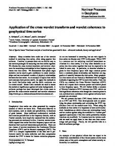
where the wk, bk and ak are weight coefficients, translations and dilations for each daughter wavelet [26]. It is perceived that the wavelet transform is an significant tool for analysis and processing of signals and images. In spite of its efficient computational algorithm, the wavelet transform suffers from three essential disadvantages: shift sensitivity, poor directionality and absence of phase information [27-32]. Most DWT applications use sectional filtering with real coefficient filters associated wih real wavelets resulting in real-valued approximations and details. Such DWT implementations cannot ensure the local phase information. All natural signal are fundamentally real-valued, hence to avoid the local phase information, complex-valued filtering is necessary [33, 34]. Latest research in the improvement of complex wavelet tarnsforms (CWTs) can be broadly classified in two groups; RCWT (Redundant CWTs) and NRCWT (Nonredundant CWTs). The RCWT contains two almost similar CWTs. They are denoted as DT-DWT (Dual-Tree DWT based CWT, see Figure 1) with two almost similar models namely Kingsbury’s and Selesnick’s [35]. In this paper, we used Kingsbury’s CWT [34, 36] for image denoising.
Wavelet is a useful tool for representing nonlinearity [26]. A function f (x) can be symbolized by the superposition of daughters ψ a,b 428
COMPARISON OF REAL AND COMPLEX-VALUED VERSIONS OF WAVELET TRANSFORM, CURVELET TRANSFORM AND RIDGELET TRANSFORM FOR MEDICAL IMAGE DENOISING Huseyin YASAR, Murat CEYLAN, Ayse Elif OZTURK wavelets and they will so isolate the discontinuity across the edge by missing the smoothness along the edge. In order to get over the weakness of wavelet transform in two or more dimensions, Candès and Donoho [17] improved a new system of representations called “ridgelets” which can effectively cover the line singularities in two dimensions. Nowadays, Ridgelets have been applied in image processing [37,38]. For each a > 0, each b є R and each θ є [0, 2π], the bivariate ridgelet : R2 → R is described as Figure 1: Complex Wavelet Transform with two level 2.2.
Ridgelet Transform
The achievement of the wavelets essentially depends on the good performance brought by the one-dimensional (1-D) piecewise smooth functions. Unfortunately, this success is not acceptable in the two-dimensional (2-D) case. Fundamentally, wavelets are good at catching zero-dimensional or point singularities. However, 2-D signals (i.e., images) generally include 1-D singularities (i.e.,edges and corners). The edges separate the smooth regions by creating discontinuity across the edge while the edges themselves are also regular along the edge. By sentience, 2-D wavelet transforms are created by the tensor products of 1-D
a ,b , ( x ) a 1/ 2 . (( x1.cos x2 .sin b) / a )
(5) A ridgelet is stable along the lines x1 cos θ + x2 sin θ = constant. Transverse to these ridges it is a wavelet and given an integrable bivariate image f (x1, x2), we can describe its ridgelet coefficients as
R (a, b, ) a ,b , . f ( x1 , x2 )dx1dx2
(6)
The ridgelet transform can be indicated in terms of the Radon transform. The Radon transform of an image f (x1, x2) is described as RA( , t ) f ( x1 , x2 ). ( x1.cos x2 .sin t )dx1dx2
(7) where δ is the Dirac distribution.
Figure 2: Ridgelet samples Thus the ridgelet transform is precisely the implementation of a 1D wavelet transform to the slices of the Radon transform where the angular variable θ is stable and t is varying. Ridgelets are different from wavelets in a sense that ridgelets exhibit so high directional susceptibility and are highly anisotropic. A fast ridgelet transform can be applied in the Fourier domain. The 2D FFT is computed firstly. Then it is interpolated along a few straight lines equal to the selected number of projections. Each line passes through the centre of the 2D frequency space, with an inclination equal to
the projection angle, and a number of interpolation points equal to the number of rays per projection. After the 1D reverse FFT along each interpolated ray, we perform a 1D wavelet transform. Pay attention to that the ridgelet coefficients so obtained are not represented in the Fourier frequency domain. The Fourier transform used is only a tool to succeed a fast application of the ridgelet transformation. Actually, it is equivalent to applying 1D wavelet transform to the Radon slices of the original pattern image. 429
COMPARISON OF REAL AND COMPLEX-VALUED VERSIONS OF WAVELET TRANSFORM, CURVELET TRANSFORM AND RIDGELET TRANSFORM FOR MEDICAL IMAGE DENOISING Huseyin YASAR, Murat CEYLAN, Ayse Elif OZTURK
Figure 3: Scheme of ridgelet transform 2.3.
Curvelet Transform
The idea of curvelets is to represent a curve as a superposition of functions of a variety of lengths and widths corresponding the scaling law width ≈ length2 [19]. This can be done by decomposing the image into subbands firstly, i.e., separating the object into series of disjoint scales. Each scale is then evaluated by means of a local ridgelet transform. Curvelets are based on multiscale ridgelets combined with a spatial bandpass filtering process to isolate different scales. This spatial bandpass filter nearly kills all multiscale ridgelets which are not in filter’s frequency range. In other words, a curvelet is a kind of multiscale ridgelet which lives in a prescribed frequency band. The bandpass is set so the curvelet length and width at fine scales are interrelated by a scaling law width ≈ length2 and so the anisotropy increases with decreasing scale like a power law. There is a very special correlation between the index of the dyadic subbands and the depth of the multiscale pyramid; the edge length of the localizing windows is doubled at per other dyadic subband, thus maintaining the fundamental property of the curvelet transform which says that elements of length about 2- j serve for the analysis and synthesis of the j th subband [2j, 2j+1]. Curvelets have a scaling corresponding 2 width ≈ length2 while multiscale ridgelets have random dyadic length and random dyadic widths. Loosely speaking, the curvelet dictionary is a subset of the multiscale ridgelet dictionary, however which allows reconstruction.
The discrete curvelet transform of a continuos function f (x1,x2) makes use of a dyadic sequence of scales, and a bank of filters ( P0 f, ∆1 f, ∆ 2 f ) with the feature that the passband filter ∆s is concentrated near the frequencies [22s, 22s+2 ], e.g., =
x
,
=
x
(8)
In wavelet theory, a decomposition into dyadic subbands [2s, 2s+1 ] is used. Contrarily, the subbands used in the discrete curvelet transform of continuum functions have the non-standard form [22s, 22s+2 ] . This is non-standard characteristic of the discrete curvelet transform well worth considering. The curvelet decomposition is the sequence of the following steps with the notations of section above, Subband Decomposition. f is decomposed into subbands f→( , , ) (9) Smooth Partitioning. Each subband is smoothly windowed into an appropriate scale’s “squares” (sidelength 2-s ) →
Renormalization. Each renormalized to unit scale =
(10)
resulting
square
is
(11) 430
COMPARISON OF REAL AND COMPLEX-VALUED VERSIONS OF WAVELET TRANSFORM, CURVELET TRANSFORM AND RIDGELET TRANSFORM FOR MEDICAL IMAGE DENOISING Huseyin YASAR, Murat CEYLAN, Ayse Elif OZTURK Ridgelet Analysis. The discrete ridgelet transform is used for analysing each square. In the definition, the ridgelet transform is applied after the two dyadic subbands [22s, 22s+1 ] and [22s+1, 22s+2 ] are merged.
We proposed a non-aliasing Curvelet transform to overcome the aliasing in Curvelet transform, namely complex Curvelet transform. The key innovation can be universalized as follows: 2D and 1D complex wavelet transform.
Figure 4: Scheme of curvelet transform 2.4.
Peak Signal-to-Noise Ratio (PSNR)
Any processing implemented to an image may cause an significant loss of information or quality. Image quality estimation methods can be subdivided into objective and subjective methods [37, 38]. Subjective ways are based on human judgment and operate without reference to explicit criteria [39]. Objective ways are based on comparisons using explicit numerical criteria [40, 41], and several references are feasible such as the ground truth or prior knowledge expressed in terms of statistical parameters and tests [42, 43]. Given a reference image f and a test image g, both M×N sized, the PSNR between f and g is defined by:
PSNR ( f , g ) 10.log10 (2552 / MSE ( f , g )) (12)
MSE ( f , g )
1 M N . ( f i , j gi , j ) 2 MN i 1 j 1 (13)
The PSNR value approaches infinity as the MSE approaches zero; this shows that a higher PSNR value provides a higher image quality. At the other tip of the scale, a small value of the PSNR implies high numerical distinctions between images. 3.
USED DATA
In this study, 32 CT images taken from Baskent University Konya Research Hospital are used. Image collection is labeled as benign or malign by an expert radiologist using biopsy reports. This labeled image database includes 32 images (12 benign and 20 malign nodules) [44]. 4.
RESULTS AND DISCUSSION
Real-valued wavelet transform (RVWT), complexvalued wavelet transform (CVWT), ridgelet transform (RT), real-valued first-generation curvelet transform (RVFG CT), real-valued secondgeneration curvelet transform (RVSG CT), complex-valued second-generation curvelet transform (CVSG CT) are implemented on the images and their parameters are obtained. Random, gaussian, salt & pepper noises are implemented to 431
COMPARISON OF REAL AND COMPLEX-VALUED VERSIONS OF WAVELET TRANSFORM, CURVELET TRANSFORM AND RIDGELET TRANSFORM FOR MEDICAL IMAGE DENOISING Huseyin YASAR, Murat CEYLAN, Ayse Elif OZTURK the image. PSNR is calculated between the noisy image and the original image. These processes repeated one hundred times for all images. Averaged value of obtained results is calculated (see Table 1). In Table 1, B signfiy an image with benign nodule and M signify an image with malign nodule. According to Table 1, highest PSNR values for removal of random noise and Gaussian noise were obtained using CWT as 34.01 dB and 32.89
dB, respectively. In case of Gaussian noise in images, PSNRs of first generation curvelet transform and complex-valued wavelet transform are around 33 dB. The ridgelet transform provides high PSNR value (30.4dB) for denoising of salt & pepper noise in images. The resulting denoised output images for random selected input image (with benign nodule) are given in Figure 5, Figure 6 and Figure 7.
Table 1: Obtained results for medical image denoising process
432
COMPARISON OF REAL AND COMPLEX-VALUED VERSIONS OF WAVELET TRANSFORM, CURVELET TRANSFORM AND RIDGELET TRANSFORM FOR MEDICAL IMAGE DENOISING Huseyin YASAR, Murat CEYLAN, Ayse Elif OZTURK
Figure 5: Denoised image outputs for random noise using multi-resolution analyses 5.
CONCLUSIONS
Figure 6: Denoised image outputs for Gaussian noise using multi-resolution analyses [3] Chuı C. K., Wu S., “An Introduction to Wavelets”, Academic Press, 1992.
In this study, multi-resolution analyses are implemented for medical image denoising and obtained results are concluded above:
[4] Meyer Y., “Wavelets and Operators”, Cambridge Studies in Advanced Mathematics 37 , 1993.
1- Ability of defining images from best to worst is: curvelet transform, ridgelet transform, wavelet transform.
[5] Mallat S., “A Theory For Multiresolution Signal Decomposition: The Wavelet Representation”, IEEE Trans. Pattern Anal. Machine Intell., vol. 11, p.p. 674–693, 1989.
2- Denoising algorithm which is improved for ridgelet analysis did not provide the expected results for random noise and gaussian noise. On the other hand, although been worse than the other transformations, it was more useful for denoising salt&pepper. 3- For the future, multi-resolution analyses can improve to other medical image denoising problems. In addition, other multi-resolution analyses can be used to make the denoising scheme more effective. The performance of this study shows the advantage of proposed method: complex version of multi-resolution analyses is very suitable for noise removal from medical images. REFERENCES [1] Morlet J., Arehs G., Forugeau I., Giard D., “Wave Propagation and Sampling Theory”, Geophysics, vol. 47, pp. 203-236, 1982. [2] Morlet J., Arehs G., “Decompsotition Of Hardy Functions into Square Integrable Wavelets of Constant Shape”, SIAM J. Math. Anal., vol. 15, no. 4, p.p. 723-736, 1984.
[6] Daubechies I., “Ten Lectures on Wavelets”, PA: SIAM , Philadelphia, 1992. [7] Coifman R. R., Wickerhauser M. V., “Entropy Based Algorithms For Best Basis Selection”, IEEE Trans. On Information Theory, vol. 38, no. 2, 1992. [8] Lawton W., “Applications of Complex Valued Wavelet Transforms to Subband Decomposition”, IEEE Trans. Sig. Proc., vol. 41, no. 12, p.p. 35663568,1993. [9] Lina J. M., “Complex Daubechies Wavelets: Filter Design and Applications”, Proc.ISAAC Conf., University of Delaware,1997. [10] Lang M., Guo H. and Odegard J. E., “Noise Reduction Using Undecimated Discrete Wavelet Transform”, IEEE Signal Processing Letters, 1995. [11] Mojsilovic A., Popovic M., Sevic D., “Classification of The Ultrasound Liver Images with The 2N X 1-D Wavelet Transform”, IEEE Int.Conf.Image, vol.1, p.p. 367-370, 1996. 433
COMPARISON OF REAL AND COMPLEX-VALUED VERSIONS OF WAVELET TRANSFORM, CURVELET TRANSFORM AND RIDGELET TRANSFORM FOR MEDICAL IMAGE DENOISING Huseyin YASAR, Murat CEYLAN, Ayse Elif OZTURK [12] Chang S.G., Yu B. and Vattereli M., “Adaptive Wavelet Thresholding for Image Denoising and Compression”, IEEE Trans. Image Processing, vol. 9, pp. 1532-1546, Sept. 2000. [13] Portilla J., Strela V., Wainwright M. J., Simoncelli, E.P., “Adaptive Wiener Denoising using a Gaussian Scale Mixture Model in The Wavelet Domain”, Proceedings of the 8th International Conference of Image Processing Thessaloniki, Greece, October 2001. [14] Chen G. Y. and Bui T. D., “”Multi-wavelet De-noising using Neighboring Coefficients”, IEEE Signal Processing Letters, vol. 10, no. 7, pp. 211214, 2003. [15] Abdulmunim M. E., “Color Image Denoising Using Discrete Multiwavelet Transform”, Department of Computer Science, niversity of Technology, 2004. [16] Benjaminsen C., “Filtering of Periodic Noise Using the Complex Wavelet Transform”, M.Sc. thesis, Informatics and Mathematical Modelling, Technical University of Denmark, DTU, 2007. [17] Candes E., Donoho D. L., “Ridgelets: The Key to High-Dimensional Intermittency”, Phil. Trans. R. Soc. Lond. A., vol. 357, p.p. 2495–2509, 1999. [18] Do M. N. and Vetterli M., “The Fnite Ridgelet Transform For İmage Representation”, IEEE Transactions on Image Processing, vol. 12, no. 1, pp. 16-28, 2003. [19] Candes E. J., Donoho D. L., “Curvelets- A Surprisingly Effective Nonadaptie Representation For Objects With Edges in Curve and Surface Fitting”, In: A. Cohen, C. Rabut and L. Schumaker, Editors, Curves and Surface Fitting: Saint-Malo 1999, Vanderbilt University Press, Nashville, pp. 105–120, 2000. [20] Donoho D. L., Duncan M. R., “Digital Curvelet Transform: Strategy, Implementation and Experiments”, Proceeding of the SPIE on Wavelet Application VII, Orlando, p.p. 12-30, 2000. [21] Candes E.J., Demanet L., Donoho D.L., Ying L., “Fast Discrete Curvelet Transforms”, tech. rep., Applied and Computational Mathematics, California Institute of Technology, pp. 1-44, 2005. [22] Starck J. L., Candes E. J., Donoho D. L., “The Curvelet Transform For Image Denosing”, IEEE Trans. Image Processing., vol. 11, p.p. 131-141, 2002. [23] Gyaourova A. , Kamath C. and Fodor I. K., “Undecimated Curvelet Transforms For Image
Denoising”, Lawrence livermore National Laboratory, Tech. Rep. UCRL-ID-150931, 2002. [24] Sivakumar R., “Denoising of Computer Tomography Images using Curvelet Transform”, ARPN Journal of Engineering and Applied Sciences. February, 2007. [25] Rayudu D. K. V., Murala S. and Kumar V., “Denoising of Ultrasound Images Using Curvelet Transform”, The 2nd International Conference on Computer and Automation Engineering (ICCAE 2010), Singapore, vol. 3, pp. 447–451, 2010. [26] Li C., Liao X. and Yu J., “Complex-Valued Wavelet Network”, Journal of Computer and System Sciences, vol. 67, pp. 623-632, 2003. [27] Shukla P. D., “Complex Wavelet Transforms and Their Applications”, PhD Thesis, The University of Strathclyde, 2003. [28] Fernandes F., “Directional, Shift-İnsensitive, Complex Wavelet Transforms With Controllable Redundancy”, PhD Thesis, Rice University, 2002. [29] Strang G. and Hguyen T.,“Wavelets and Filter Banks”, Wellesley-Cambridge Press, 1996. [30] Oppenheim A.V. and Lim J.S., “The Importance Of Phase in Signals”, Proc. IEEE, vol. 69, pp. 529-541, 1981. [31] Lorenzetto G. P. and Kovesi P., “A Phase Based Image Comparison Technique”, DICTA99, University of Western Australia, 1999. [32] Driesen J. and Belmasn R., “Time-Frequency Analysis in Power Measurement Using Complex Wavelets”, IEEE Int. Sympo. On Circuits and Systems, ISCAS2002, pp. 681-684, 2002. [33] Lina J.M., “Image Processing With Complex Daubechies Wavelets”, Journal of Math. Imaging and Vision, vol. 7, pp. 211-223, 1997. [34] Bulow T. and Sommer G., “Hypercomplex Signals- A Novel Extension of The Analytic Signal to The Multidimensional Case”, IEEE Transactions on Signal Processing, vol. 49, pp. 2844-2852, 2001. [35] Selesnick I. W., Baraniuk R. G. and Kingsbury N. G., “The Dual-Tree Complex Wavelet Transform”, IEEE Signal Processing Magazine, vol.22, pp. 123-151, 2005. [36] Donoho D.L., “De-Noising by SoftThresholding”, IEEE Transactions On Information Theory, vol. 41, pp. 613-627, 1995. [37] Kreis R., “Issues of Spectral Quality in Clinical H-Magnetic Resonance Spectroscopy And 434
COMPARISON OF REAL AND COMPLEX-VALUED VERSIONS OF WAVELET TRANSFORM, CURVELET TRANSFORM AND RIDGELET TRANSFORM FOR MEDICAL IMAGE DENOISING Huseyin YASAR, Murat CEYLAN, Ayse Elif OZTURK A Gallery Of Artifacts”, NMR in Biomedecine, vol. 17, no. 6, pp. 361-381, 2004.
Detectors”, Pattern Recognition Letters, vol. 21, no.9, pp. 805-816, 2000.
[38] Avcibas I., Sankur B. and Sayood, K., “Statistical Evaluation of Image Quality Measures”, Journal of Electronic Imaging, vol. 11, no. 2, pp. 206-223, 2002.
[42] Elbadawy O., El-Sakka M. R. and Kamel M. S., “An Information Theoretic Image-Quality Measure”, Proceedings of the IEEE Canadian Conference on Electrical and Computer Engineering, vol. 1, pp. 169-172, 1998.
[39] Farrell J. E., “Image Quality Evaluation in Colour Imaging: Vision And Technology”. MacDonald, L.W. and Luo, M.R. (Eds.), John Wiley, pp. 285-313, 1999. [40] Cadik M. and Slavik P., “Evaluation of Two Principal Approaches to Objective Image Quality Assessment”, 8th International Conference on Information Visualisation, IEEE Computer Society Press, pp. 513-551, 2004.
[43] Dosselmann R. and Yang X. D., “Existing And Emerging Image Quality Metrics”, Proceedings of the Canadian Conference on Electrical and Computer Engineering, pp. 1906-1913, 2006. [44] Ceylan M., “A New Complex-Valued Intelligent System Design on Evaulating of The Lung İmages With Computerized Tomography”, PhD Thesis, Selcuk University, Graduate School of Natural and Applied Sciences, May, 2009
[41] Nguyen,T.B. and Ziou, D., “Contextual and Non-Contextual Performance Evaluation of Edge
435
COMPARISON OF REAL AND COMPLEX-VALUED VERSIONS OF WAVELET TRANSFORM, CURVELET TRANSFORM AND RIDGELET TRANSFORM FOR MEDICAL IMAGE DENOISING Huseyin YASAR, Murat CEYLAN, Ayse Elif OZTURK
436