Comparison of Synchronous Condenser and STATCOM for Inertial Response Support Yang Liu, Shuitao Yang, Shao Zhang and Fang Zheng Peng Electrical and Computer Engineering Department, Michigan State University, East Lansing, USA,
[email protected] Abstract—This paper shows a comparison between synchronous condenser (SC) and STATCOM in terms of inertia frequency response (IFR) with synchronous generator (SG). It has long been argued that, as a rotating-mass-based reactive power compensation device, SC will contribute to the total inertia of the network from its stored kinetic energy. Whereas, its counterpart, the voltage source converter (VSC) based STATCOM, will only supply reactive power and maintain voltage balance. However, the energy stored in the dc-link capacitor of the STATCOM, especially the cascaded inverter based STATCOM whose dc-link capacitance is relatively large, if properly controlled, can also contribute to the IFR. A matlab/Simulink model of SG equipped with SC and STATCOM is presented in this paper. It is demonstrated that STATCOM can provide competitive or even better IFR during disturbance condition. Both theoretical and simulated results are provided.
I.
INTRODUCTION
Synchronous generator (SG) has been in service in US power system from long back. The operation and control of a SG is mature in practice and it helps to maintain the power system reliability and stability. However, with the advancement of modern power system and increasing types of load, the requirement for the transient stability has become more rigid. Various reactive compensation devices have been called for to support power system stability. These devices can be roughly classified into three major categories: synchronous condenser (SC), static var compensator (SVC), and static synchronous compensators (STATCOM).
eliminates the bulky transformers and will respond much faster. It is well suited for var compensation/generation applications [6]. Since there is no mechanical part in VSC based STATCOM, it has long been admitted that STATCOM makes no contribution to the frequency stability of the SG during load disturbance. However, STATCOM can be properly controlled to make virtual inertia response. The stored energy in dc-link capacitor can be utilized by varying the dc-link voltage during disturbance condition. This proposed methodology focuses on short-term oscillations and incorporates no long-term power regulation, thus it needs no mass storage device. Moreover, since SC and SG are synchronized with the transmission network, the largest allowable frequency deviation is limited and locked by the system. In some scenario, the STATCOM will demonstrate even better performance in terms of inertia frequency support than SC. This is very attractive in power system applications since bidirectional VSCs can work in generative and motoring modes similar to SMs. The rest of the paper is organized as follows. Section II shows the frequency response of a SG. Section III describes operation principle of SC and its integration with SG. Section IV addresses nominal operation of the CMI-based STATCOM and modified virtual inertia control (VIC). Simulation results and discussions are presented in Section V. Conclusion and future work are included in Section VI. II.
FREQUENCY RESPONSE OF SYNCHRONOUS GENERATOR
A synchronous condenser, by its nature, is a synchronous generator operating without a prime mover. It supports network voltage by providing reactive power compensation and additional short circuit power capacity. Furthermore, it can also support system frequency stability by increasing network inertia.
The transient frequency response of the synchronous generator, according to its time frame range, can be roughly divided as inertial frequency response (IFR), primary frequency response (PFR) and secondary frequency response (SFR) [2].
STATCOM, arising from the family of FACTS device, has been utilized widely in recent years. A STATCOM is a controlled reactive power source, which typically includes a voltage source converter (VSC) and a DC link capacitor connected in shunt through coupling transformer, capable of generating and/or absorbing reactive power. Alternatively, cascaded multilevel inverter (CMI) based STATCOM
In the first few milliseconds or seconds following the loss of a large power generator or the increase of load command, the grid frequency starts to drop. These initial frequency dynamics are regulated by the inertial response of the generators that still remain online. The synchronous generators release their stored kinetic energy into the grid, reducing the initial rate of change of frequency (ROCOF)
978-1-4799-5776-7/14/$31.00 ©2014 IEEE
2684
and allowing governor to catch up and contribute to frequency stabilization [4]. It is the first step and the natural response of a SG under load disturbance.
Frequency (Hz)
60.4
The step following the IFR is the Primary Frequency Response (PFR). PFR can be understood as the instantaneous proportional increase or decrease in real power output in response to system frequency deviations. This response is in the direction that stabilizes frequency. It is attained due to governor action to instantly act relative to the frequency deviation. This usually takes place within seconds to tens of seconds. Finally, it is the secondary frequency response (SFR). SFR is executed by automatic generation controller (AGC) and often referred to as load frequency controller (LFC). The AGC utilizes reserves to restore the frequency closer to scheduled frequency. Generally, the SFR can take place from seconds to minutes. These three steps happen sequentially so that frequency is recovered back to 60 Hz [3]. Fig.1 shows a diagram of governor power frequency control. The analysis of this paper is focused on the inertial frequency response. Δω 1 R
−
KI s
ΔP
+
+
+ +
1 Ms+ D
60 59.8 59.6 0
5
10
15 Time (s)
20
25
30
5
10
15 Time (s)
20
25
30
Power (p.u.)
1.3 1.2 1.1 1 0.9 0
Fig. 2. Typical system frequency response for a generation outage.
The energy generated by the generator is relatively large. However, the available energy during the initial transient of the system is not that much since the SG needs to be in synchronism with the system. The grid code has set up the minimum frequency drop it can be, and it is typically within the range of 0.1-1 Hz [2]. Thus, the actual available inertia energy is proportional to its inertia constant H, 1 2 1 2 Jωom − Jωmin (ω 2 − ω 2 ) 2 H _ available = 2 ∝ om 2 min ⋅ H MVA ωom
ΔPL ' m
60.2
Δω
(3).
Only this limited amount of energy will be utilized for IFR. Here inertial constant H is adopted to describe the different ratings of the SG. As can be seen from Fig. 3, the actual available inertia energy is in the time frame of 70-300 ms.
ΔPm'' +
1 R
Δω
inertial energy constant (ms)
Fig.1. governor power frequency control.
During the period of IFR, the frequency variation, directly after a significant generation-load imbalance, is determined by the equation ⎛1 ⎞ d ⎜ ⋅ J system ⋅ ωel2 ⎟ 2 ⎠ Pm − Pe = ⎝ dt
(1),
where Pm is the generated power, Pe is the demanded power. The right side of the equation is the derivative of the kinetic energy stored in the generator. Another constant called H constant (also known as inertia constant) is defined as [3] H=
2 Stored energy at rated speed in MW ⋅ S 1 Jωom = MVA rating 2 VAbase
(2).
The inertia constant is measured in seconds and it falls typically in the range of 2-9 s for large power plants [1]. Fig. 2 and shows a typical waveform of a SG subjected to a loss of generation unit or a sudden increase in load. If the inertia available in the grid is large, the drop in frequency is not that much. The nadir drops down to 59.65 Hz in this case. When the frequency drops, the inertia energy from SG is automatically released.
f-min=59.0 Hz(67~300 ms)
300 250
f-min=59.3 Hz (46~210 ms)
200 150
f-min=59.6 Hz (27~120 ms)
100 50 0 2
f-min=59.9 Hz(6.7~30 ms)
3
4 5 6 7 8 SG Typical inertia constant (s)
9
Fig. 3. Available inertial energy from SG with different minimum frequency.
Given this very limited value of available inertia constant of SG, it is worthy studying the possible methods of improving IFR. Like mentioned previously, SC, SVC and STATCOM are the most three frequently used reactive power compensators, and among which, only SC have been claimed to contribute to the total inertia of the system. However, it is not the obvious truth. The following section will address the possible contribution from STATCOM for IFR and a comparison between SC and STATCOM have been made.
2685
III.
IV.
FREQUENCY RESPONSE OF SYNCHRONOUS CONDENSER
SC has been used since 1930 as a source of dynamic VARs (both inductive and capacitive) to improve system stability and support voltage under varying load conditions and contingencies. Its field is controlled by a voltage regulator to either generate or absorb reactive power as needed to control the voltage of the power system. The synchronous condenser is a rotating machine without a prime mover. Because of this, they can provide a lower inertia from the kinetic energy stored in the rotating mass. The typical H value of SC is 1-1.25 s [1], thus the available inertial energy from the SC can be estimated similarly using equation in (3). As can be seen from Fig. 4, the actual available inertia energy of SC is in the time frame of 3-41 ms. 50 45 f-min=59.0 Hz (33~41 ms) Inertial energy constant (ms)
40
MODELING AND ANALYSIS OF STATCOM FOR FREQUENCY SUPPORT
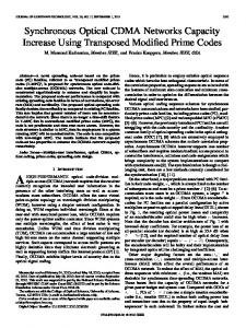
It has been witnessed that VSC based STATCOMs are built all over the world. However, the benefit of STATCOM is not fully potential. As a VSC based reactive compensator, STATCOM has been penalized for not being able to help with frequency regulation. The reason is that it has no rotating mass thus has no stored kinetic energy. However, it will be shown in this section that electric energy stored in the dc-link capacitor of STATCOM, especially for the CMIbased STATCOM, has large electric energy stored, will signicantly help the inertial response if properly controlled. A. Normal operation of STATCOM Basically, the STATCOM system is connected to the weak grid bus at PCC. The CMI-based system is composed of three main parts: a multilevel-cascaded VSC with separate DC sources, a coupling inductor and a controller, as shown in Fig. 6 [9].
35 f-min=59.3 Hz(23~29 ms)
30 25 20
f-min=59.6 Hz (13.3~16.6 ms)
15 10
0 1
Fig. 6. Single line diagram of the cascaded multilevel inverter based STATCOM.
f-min=59.9 Hz (3~4.2 ms)
5 1.125
1.25
SC Typical inertia constant (s)
Fig. 4. Available inertial energy from SC with different minimum frequency.
Fig. 5 shows a typical connection of a SC with SG. As have been discussed in [5], SC shows a good dynamic performance for reactive power compensation. Furthermore, SC will contribute to the total inertia of the system as well and the ROCOF is reduced.
The exchange of real and reactive power between cascaded inverter and the power system can be controlled by adjusting the amplitude and phase angle of the converter output voltage. Usually, it can be divided into capacitive mode and inductive mode, as shown in Fig. 7. Two important control laws of cascaded-multilevel VSC for STATCOM application [9]: 1.
2.
Fig. 5. SG with SC connected to load bus.
Although the benefit of SC, the drawback of synchronous condenser is that it calls for high demand of cooling for thermal consideration and it cannot be controlled fast enough to compensate for rapid load changes.
The amount of transferred reactive power (Q) can be controlled by adjusting the magnitude of converter output voltage; The amount of transferred real power (P) can be controlled by adjusting the phase angle of the converter output voltage with respect to the voltage at PCC.
B. Inertia energy from STATCOM As a VSC based reactive power compensator, STATCOM have no real “inertia”. However, we use a term of virtual inertia constant in this paper, similar as defined in [6], associated with the inertia constant in synchronous rotary condensers,
For the above two perspectives, STATCOM shows a better performance since VSC based FACTS device has a much quicker response time and very low thermal design requirement.
2686
H STATCOM
1 C ⋅ N ⋅ (Vdc2 _ max − Vdc2 _ min ) 2 = S STATCOM
(4).
T /4
ΔQi = Ci = ΔVdc
∫θ
i (t )
2 I cos ωtdt 2εVdc
=
2 I (1 − sin θ i ) 2ωεVdc
(5).
Therefore, the total capacitance for a three-phase M-level inverter is, ( M −1) / 2
C =3
∑C
i
(6).
i =1
(a). operation in non-ideal condition
Table I shows the parameters used for the analysis and experimental setup. TABLE I. SYSTEM PARAMETERS FOR SIMULATION AND ANALYSIS
Parameter S (rated power) Vs0 (ph-ph rms) Vdc Vdcmin Vdcmax Number of CMI per phase H-bridge capacitance
(b). operation in lossless condition Fig. 7. Normal operation of STATCOM as Var generator.
The voltage rating of the dc link is determined by the connected network. A detailed analysis can be referred to [7]. Fig. 8 shows a schematic for CMI-based STATCOM for the utility connected application.
Value 1 MVA 13.8 kV∠0, 60 Hz 600 V 540 V 840 V 22 (10% redundancy) 4700 μF
Therefore, the relationship between initial dc link voltage (Vdc0), dc-link capacitance (Cdc) and inertia constant from STATCOM (HSTATCOM) is shown in fig. 9. 1.4
in e rtia c o n s ta n t o f S T A T C O M (s )
1.2
1.5 1
1
0.8
0.6
0.5
Fig.8. SG with STATCOM connected to load bus.
Dc-link voltage has limited variation range. For the design of CMI-based STATCOM, some redundancy has been considered and in this analysis, 10% redundancy is used so the minimum voltage rating is taken to be 0.9 pu. Besides, the maximum voltage Vdcmax cannot exceed the voltage ratings of the power semiconductor devices and dclink capacitors. In this analysis, 1.4 pu is taken as the upper limit. Another important parameter that determines the energy capacity is the dc link capacitor. For the proposed cascade inverter, since each phase has its own separate dc capacitors, calculation of the required capacitance of each H-bridge dc capacitor needs to cover both positive-sequence and negative-sequence reactive power [7]. The required capacitance, Ci, can be formulated as
0.4
0 9000 8000 7000 6000 5000 4000 3000 2000 DC link capacitance (uF)
550
750 700 650 600 initial DC link voltage (V)
800
0.2
Fig. 9. Relationship between Vdc, Cdc and HSTATCOM.
A comparison between SC and STATCOM for possible available inertial energy using parameters from Table I is shown in Fig. 10. As can be obtained from Fig. 10, STATCOM can provide possible competitive inertia energy compared to SC, and under some conditions, it will provide even more inertia energy. This is largely because that although the inertia response from SG and SC is natural and automatic, it obviously limited by the frequency deviation due to the grid code. However, as a voltage controlled device, the STATCOM is independent of that requirements and can provide large inertia energy given enough short term energy storage.
2687
The virtual inertia constant HSTATCOM can be obtained by equating the SG power variation in (9) with capacitor power in (10) yields,
f-min=59.0 Hz (33~41 ms)
40
Inertial energy constant (ms)
35 30
DeltaVdc=0.5 pu f-min=59.3 Hz (23~29 ms)
25
2
20 15
DeltaVdc=0.3 pu
f-min=59.6 Hz (13.3~16.6 ms)
0 1
f-min=59.9 Hz (3~4.2 ms) DeltaVdc=0.1 pu
1.125
1.25
SC typical inertia constant (s)
2 2 2 H STATCOM ⋅ f NCVDC NCVDC 0 = + 2 H STATCOM − f0 2S STATCOM 2 S STATCOM
Fig. 10. Theoretical inertial energy comparison between STATCOM and SC.
⎡ ⎛ d ⎞⎤ V + ωLI *pq − ⎜ L I *pd + RI *pd ⎟⎥ ⎡V pd* ⎤ ⎢ Sd ⎝ dt ⎠⎥ ⎢ * ⎥=⎢ ⎣⎢V pq ⎦⎥ ⎢VSq − ωLI *pd − ⎛⎜ L d I *pq + RI *pq ⎞⎟ ⎥ ⎢⎣ ⎝ dt ⎠ ⎥⎦
(7),
and ⎧V * = V *2 + V *2 pd pq ⎪⎪ p * ⎛ ⎞ V ⎨ * pq −1 ⎪α p = tan ⎜⎜ V * ⎟⎟ ⎪⎩ ⎝ pd ⎠
(8).
The typical control of CMI-based STATCOM is known as balancing control and individual control. The traditional control principle is to maintain the DC link voltage stable and balanced between different modules. In this study, since it is desired to utilize the energy stored in the DC link capacitor during load disturbance or frequency variation, a modified control strategy is utilized. Similar deviation has been adopted in [10]. The equation of the machine angular motion is given in (9): 2 H df ⋅ = PM − PE = ΔP1 ( pu) f 0 dt
* = VDC
4S STATCOM H STATCOM ⋅ f − K2 NCf 0
(13).
2 where, K 2 = (4SVSC H VSC ) /( NC ) − VDC 0 Based on the above analysis, the virtual inertia control (VIC) strategy of the STATCOM is presented in Fig. 11. It is modified from traditional control. To verify the working principle of the proposed VIC controller, a simulation has been carried out. The simulated waveform is shown in Fig. 12. The active current reference is commanded from frequency variation and reactive current reference stays constant. It can be seen that Ipd rapidly tracks the step-changing reference while the reactive current Ipq remains unchanged. Complete decoupled control is achieved. Next section will show simulation results of the STATCOM with the proposed VIC control in system study.
0.8 0.7 0.6
I *pd
I pd
0.5 0.4
I pq
I *pq
0.3 0.2 0
(9).
In order to equate the available power of the dc link capacitors to that of an electrical machine, the capacitor dynamics (in terms of dc link voltage and output power) are presented in (10):
( pu )
(12).
Then the new dc-link voltage reference can be obtained as,
Current (p.u.)
C. Virtual inertia control for STATCOM In order for the STATCOM to generate desired active current (id*) and reactive current (iq*). The decoupling feedforward and feedback control has been used as the controller [8]. The relationship is given as in
NCVDC dVDC ⋅ = Pin − Pout = ΔP2 S STATCOM dt
(11).
The new dc link voltage reference is obtained through the relationship between frequency variation and inertial energy can be used from dc link,
10 5
WSTATCOM WSTATCOM H STATCOM H 2 WK + WSTATCOM NCVDC dVDC WK + WSTATCOM df df ⋅ = ⋅ + ⋅ f0 dt S STATCOM dt f0 dt
(10).
2m
4m
6m 8m Time (s)
10m
12m
14m
Fig. 12. Simulated waveforms showing virtual inertia based decoupling feedback control for CMI-based STATCOM.
V. SIMULATION RESULTS The effectiveness of the proposed VIC of STATCOM is validated in Matlab/Simulink. The tested system is a twoarea-four-machine system [3]. It compromises with two fully
2688
K2
-
+
4S STATCOM H STATCOM NCf 0
frequency
Vs
PLL
Virtual Inertia Control Vsd Vsd (=Vs)
Vdc*
+
-
+
I *pd
PI
PI
+
-
I pd
Vdc
I pq
I *pq
-
+
-
ωLs ωLs PI
Decoupling Feedback Control
-
V pd*
+
V pd
+
-
STATCOM
-
V pq*
(can be seen as a unity transfer function)
V pq -
I pd
1 sLs + Rs
+
ωLs
ωLs
-
+ Vsq (= 0)
I pq
1 sLs + Rs
+ Vsq
Control Plant
Fig. 11. Virtual inertia control for CMI-based STATCOM. 60.5 60.4
Frequency (Hz)
symmetrical of four machines, and good for studying low frequency electromechanical oscillation and inertial response of the generator. Each generator equipped with its own governor and excitation control [11]. The system illustration is shown in Fig. 13. The tested CMI-based STATCOM and SC are connected to load bus at L7 and L9 for system dynamic performance comparison.
60.3
SG+STATCOM (C=4700 uF) inertial control
60.2
SG+SC inertial control
60.1
SG+STATCOM (C=5600 uF) inertial control
60 59.9 59.8
0
1
2
3
4
5
6
7
8
9
10
0.3
PSTATCOM (pu)
0.2
SG+STATCOM (C=5600 uF) inertia control
0.1 0 -0.1
SG+STATCOM (C=4700 uF) inertial control SG+SC inertial control
-0.2 -0.3 -0.4
Fig. 13. Two-area-four-machine system.
0
1
2
3
4
5
6
7
8
9
10
Time (s)
Fig. 14. System response for 10% loadshed. 60.3 60.2
Frequency (Hz)
A. Case I. Variation in DC-link capacitance The first simulation study was carried out for variation of dc-link capacitance of CMI-based STATCOM. By changing the dc-link short-term energy storage of the STATCOM, a series of IFR from VIC based system can be obtained. ΔVdc=0.3 pu. The rest of the parameters is in accordance in Table I. This is compared with SC with H=1.25 s. The disturbances include load increase and load decrease, respectively. Simulation results are shown in Fig. 14 and Fig. 15. As can be seen from Fig.14 and Fig. 15, with the VIC based STATCOM, the ROCOF of SG is damped, this will largely improve the system stability. Since very limited frequency deviation, SC released very limited energy for the IFR and STATCOM perform better during this period of time.
60.1 60 59.9 59.8 59.7 59.6 59.5
0
1
2
3
4
5
6
0
1
2
3
4
5
6
0.5 0.4 0.3 0.2 0.1 0 -0.1 -0.2 -0.3
Fig. 15. System response for 10% load increase.
2689
B. Case II. Variation in allowable dc-link voltage The second simulation study was carried out for variation of allowable dc-link voltage of CMI-based STATCOM. By changing the depth of voltage variation, a series of IFR from VIC based system is illustrated. Cdc=4700 μF. The rest of the parameters is in accordance in table I. This is compared with SC with H=1.25 s. Simulation result is shown in Fig. 16. 60.15 SG without STATCOM or SC
60.1
Network frequency (Hz)
60.05 60 59.95
SG +SC inertial control
SG +STATCOM (deltaVdc=0.5 pu) inertial control
59.9 59.85
SG +STATCOM (deltaVdc=0.35 pu) inertial control
59.8 SG +STATCOM (deltaVdc=0.2 pu) inertial control
59.75 59.7 59.65 0
2
4
6 Time (s)
8
10
12
Fig. 16. Simulation results for different conditions as of inertial energy response.
Like mentioned previously, the different inertia values of STATCOM can be obtained by varying capacitance value and dc-link voltage. From a practical point of view, once the STATCOM is installed there, its capacitance cannot be varied easily. So variation of dc-link voltage makes more practical sense. As can be seen from the simulation results, the generator without STATCOM or SC will suffer from a high oscillation and the lowest frequency can be 59.7 Hz. With the help of inertial energy from SC, the system operation will be better, although not as good as the STATCOM inertial control. Since it is locked by the system frequency to make synchronized with the system. For the STATCOM to provide this inertial energy, as we allow more deviation for DC link voltage, the frequency deviation will become smaller thus will benefit the system stability and reliability. VI.
Experimental results will be involved in future paper to demonstrate the proposed control strategy. REFERENCES [1]
W. E. Corporation, Electrical transmission and distribution reference book: Westinghouse electric & manufacturing Company, 1942. [2] NERC Frequency Response Initiative, April, 2010. [3] P. Kundur, “Power System Stability and Control” The EPRI Power System Engineering Series, McGraw-Hill, 1994. [4] E. Muljadi, V. Gevorgian, M. Singh, S. Santoso, “Understanding Inertia and Frequency Response of Wind Power Plants” presented at the 2012 IEEE Symposium on Power Electronics and Machines for Wind Applications (PEMWA 2012) on July 16-18, 2012 in Denver, Colorado. [5] S. Teleke, T. Abdulahovic, T. Thiringer, and J. Svensson, “Dynamic performance comparison of synchronous condenser and SVC” IEEE Transactions on Power Delivery, Vol. 23, No. 3, pp.1606-1612, July, 2008. [6] F. Z. Peng, J. W. McKeever, and D. J. Adams, “A power line conditioner using cascaded multilevel inverters for distribution systems,” IEEE Trans. Ind. Appl., vol. 34, no. 6, pp. 1293–1298, Nov./Dec. 1998. [7] F. Z. Peng, J. S. Lai, J. W. McKeever and J. VanCoevering, "A multilevel voltage-source inverter with separate dc sources for static var generation," IEEE Transactions on Industry Applications, vol. 32, pp. 1130-1138, 1996. [8] F. Z. Peng and J. S. Lai, “Dynamic performance and control of a static var generator using cascade multilevel inverters,” IEEE Trans. Ind. Applicat., vol. 33, pp. 748–755, June 1997. [9] S. Sirisukprasert, A. Q. Huang, and J.-S. Lai, “Modeling, analysis and control of cascaded-multilevel converter-based STATCOM,” in Proc. IEEE Power Eng. Soc.General Meeting 2003, Jul. 13–17, 2003, vol 4, pp. 2561–2568. [10] J. Zhu, C. D. Booth, G. P. Adam, A. J. Roscoe, and C. G. Bright,“ Inertia emulation control strategy for VSC-HVDC transmission systems,” IEEE Trans. Power Syst., vol. 28, no. 2, pp. 1277–1287, May, 2013. [11] IEEE Working Group on Prime Mover and Energy Supply Models for System Dynamic Performance Studies, "Hydraulic Turbine and Turbine Control Models for Dynamic Studies," IEEE Transactions on Power Systems, Vol.7, No.1, February, 1992, pp. 167-179.
CONCLUSION
A virtual inertial control for the CMI-based STATCOM is introduced in this paper. Its contribution to inertial frequency response has been compared with SC. With the modified virtual inertia control of the DC link voltage, STATCOM can provide competitive inertial energy response as SC or provide even better response. Since this electric inertia is not limited by the system frequency rather its own dc link capacitance (short term energy storage) and dc link voltage variation, it is attractive to system study of STATCOM. A 1-MVA cascaded inverter based STATCOM is under construction in lab. It is expected to carry out the experiment using the proposed controller on STATCOM.
2690