Comparison of UML and Text based Requirements Engineering Brian A. Berenbach Siemens Corporate Research, Inc. 755 College Rd. East Princeton, NJ 08540-6632 Tel. (609) 734-3395
[email protected] ABSTRACT
Clearly, what is suitable for one organization may not work with another (even when they are in the same company). Complicating the situation are corporate goals requiring CMM or CMMI level attainment.
There appears to be a real dichotomy in the use of the UML vs. text based Use Case development for requirements elicitation and documentation, that is, on those projects where use cases are work products. Not only are there different processes in place for text and graphical use case modeling, but also there are a variety of approaches and philosophies in each camp. This paper will discuss the prose vs. graphical approaches to requirements elicitation, observed advantages and disadvantages of each, and suggest best practices for improving and/or creating effective processes for requirements elicitation.
2. MISCONCEPTIONS Misconceptions are sometimes a major driving force behind process structure. Many companies and organizations have a solid understanding of requirements processes, some do not. In this section, I will list some common misconceptions and explain how they can distort the requirements elicitation process. Section 9 provides recommendations to mitigate some of the problems caused by such misunderstandings.
Categories and Subject Descriptors D2.1 [Requirements/Specifications]: Methodologies, Tools.
Elicitation
methods,
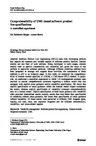
Any subject matter expert can become a requirements analyst after a week or two of training. (Figure 2) Requirements engineering requires solid knowledge of the CMM/CMMI, strong knowledge engineering skills, the ability to organize and manage a data set of requirements, quality written and visual presentation skills, and the ability to extract and model business processes using both text and graphical (e.g. IDEF, UML) techniques (whew!). Even when developing text-based use cases, novice analysts sometimes struggle mightily with the idiosyncrasies of text editors.
General Terms Management, Measurement, Documentation, Verification.
Keywords UML, Requirements, Analysis, Process
1. INTRODUCTION Siemens Corporation manufactures diverse sets of products in the medical, communication, transportation and manufacturing fields. As a member of the Siemens Corporate Research staff, I have participated in the development of some of these products. There are many corporate processes and practices when it comes to requirements elicitation. We have observed approaches to requirements elicitation and documentation ranging from absurd to “best practices” to extreme, with most organizations doing their best to struggle with processes and technology that they sometimes view as “shaky”, “suspect” or “excessively complex”.
I recently had one new medical staffer turned analyst ask me if I could spend an “hour or two” teaching him the UML. I responded that I would trade, I would spend an hour teaching him the UML and then he could spend an hour teaching me heart surgery. My experience has been that about three years are needed for an analyst to be able to lead an effort, a bit less to be a major contributor. Experienced IT professionals with good communication skills can come up to speed sooner.
On one project, all the requirements for a major new product were supposedly detailed on one PowerPoint slide as a block diagram. In another case, the requirements for a taxation system for a major telecom company were described in a two-page document. Going to the other extreme, a third company had over ten thousand requirements for an IT product in a repository.
A UML Business Model is “just a bunch of diagrams.” A UML model is just that, a model of a set of business processes. The diagrams are views into the model, just as an entity relationship diagram is a partial view of a data model. I think that this misconception is caused by a lack of skill with the UML and a lack of understanding as to how to create and utilize models. This will be discussed in more detail later.
Copyright is held by the author/owner(s). OOPSLA’04, Oct. 24–28, 2004, Vancouver, British Columbia, Canada. ACM 1-58113-833-4/04/0010.
Text based use cases are easier to develop than graphical use cases. The situation is, in many cases, reversed. On many projects I have found model-driven requirements development to be
247
significantly faster than the equivalent effort would have been using text artifacts.
(e.g. DOORS, Caliber, Requisite Pro) and associated with the parent feature. Traces then exist: •
Non-functional and functional requirements can be elicited using separate teams and processes. The subject domains for non-functional and functional requirements are indeed different (e.g. software architecture vs. insurance), however, non-functional and functional requirements may be related, may impact each other and may result in iterative changes as work progresses. Team isolation may do more harm than good.
• •
From the feature to the detailed requirements (implicit parent/child relationship) From the feature to the use case document (realized by) From the use case document text back to the detailed requirements (derives from)
As the documents pile up, the documents pile up. If the projects/teams are large the number of documents associated with a product can increase rapidly. In fact, the volume of material can increase so rapidly that navigation becomes unmanageable.
3. TEXT-BASED USE CASE ELICITATION Text based use case elicitation relies on document templates to provide a measure of structure. Topics covered include preconditions, post-conditions, included and extending use cases, main and alternate workflows, actors and miscellaneous other issues. There can be serious problems with this approach, some of which are immediately apparent; some do not surface until after a considerable amount of work has been done (Figure 1). Major issues arising when using text based use cases are listed below.
This afternoon, look over this set of product requirements and make sure they are all ok
The relationships between actors, use cases, workflows must be explicitly defined. Graphical artifacts must be described textually with the resultant confusion and potential for errors and misunderstandings associated with the translation process. When teaching courses on requirements, I sometimes present a map of the United States to the students and ask them to describe it in prose. Use cases must be predefined. When defining work assignments with text-based use cases, the separation of work, document titles and subject areas to be covered are of necessity predefined. This leads to all kinds of potential problems, such as frequent document reorganizations and rewrites. Figure 1 Problems with Prose Use Case Elicitation
Use case documents are not use cases. In order to force a uniform structure on work products, documents are organized as use cases. However, what they typically become is sets of related use cases incompletely defined in a document. I say incompletely defined because hierarchical decomposition stops at the predefined use case level. For example, a team is defining the feature details associated with a car. A use case might be “Power Windows”. This is really not a use case, but is a set of related use cases such as “lower window to pay toll” and “lock rear windows to prevent injury to children”. Now process elicitation starts, with possible loss of detail or missing use cases such as “paying a toll”, where the discovery would be made that a requirement is needed to jog the window all the way down with one light press when paying a toll.
Problems encountered with large document sets (Figure 1) include: • • • •
Difficulty in getting stakeholders to review the material, Problems finding and/or fixing traces between requirements, Issues related to new features that cross-cut existing documentation and Problems passing the material on to development (e.g. rebellion).
The above concerns may give the impression that prose use cases are not effective tools for requirements elicitation. In fact, there are ways to mitigate the problems inherent in this approach; they are described later in this paper.
Requirements extraction can be problematic with written usecases. Once the documents have been completed, it is necessary to extract the requirements. Extraction can be problematic depending on the skill of the writer. On occasion, when reviewing use case documents I have found five or more requirements packed into a single sentence.
4. MODEL-DRIVEN REQUIREMENTS ENGINEERING Model driven requirements engineering is a totally different approach, with a different set of advantages and disadvantages.
Tracing requirements in and out of use case documents can be difficult. A feature results in the creation of one or more use case documents, and those documents have detailed (testable) requirements, discovered during the creation of the use case. The detailed requirements are then placed in a requirements repository
Some of the advantages are: •
248
Use case relationships (e.g. includes, extends) are intrinsic to the diagrams.
• •
Talent for creating Use Case Models is not all that available. On many projects where modeling is done with the UML, participants are doing it for the first time. In those cases where the participants have prior experience, they may not leverage the underlying model, but rather use the UML primarily as a diagramming tool for illustrations.
It is easy to get stakeholders to sit in on visual presentations of scenarios. The work product is a single database that can be queried and altered programmatically.
Problems observed with this approach are fairly common:
In one case at a major telecom, the staff had spent two months converting a database schema into class diagrams. When asked why they didn’t simply connect the tool to the database and execute the “reverse database into model” function, they were shocked to find out that the function even existed.
Tools really aren’t there yet. The tools needed to build quality UML Use Case Models leave a great deal to be desired. There are a variety of reasons for this, one of which can be laid at the doorstep of the Object Management Group (OMG) [6]. By attempting to make UML all things to all people, it gets complex. Tool vendors struggle with the implementation, and then tool users have difficulty with the resultant complexity.
Why are all these eggs in your diagrams?
CASE Tool
It’s Easter.
Cr e ate /U
pda t
La un c
Cr e ate /U
Requirements Database
Figure 2 Experienced UML Resource can be Hard to Find Effective processes for model creation are not well known. Such processes do exist [6], but they are not sufficiently mature to become standard practice. The Rational Unified Process [7], one of the better-known techniques, is complex and vague; novices are left wondering how and where to begin. Moreover, techniques that work with five use cases typically break down when there are five hundred use cases. Issues of coherence, navigation and tool use are not well defined.
e
Use case h
pda t
Reference
e
Use case
Requirement
Figure 4 Syntheses of Graphical and Prose Processes
5. THE SYNTHESIS OF TEXT-BASED AND MODEL-DRIVEN REQUIREMENTS ENGINEERING
Requirements extraction from UML Models is problematic. Techniques for extracting requirements from UML models are not sufficiently well understood to be standard practice [4]. “Ok, I have these several hundred use case, sequence, collaboration, class and activity diagrams, now how do I determine what is and is not a requirement?” Lack of standard process reinforces the misconception that a UML model is “just a bunch of loosely related diagrams”. The UML standards do not help; they provide the semantics of a graphical language, but do not provide any guidance on the processes by which those diagrams are created.
UML Diagrams
UML Model
Reference
Text Editor
Configuration Mgmt View
It is possible, with careful planning and tool support, to synthesize the two approaches (Figure 4). The operative word is planning. Given that the model operated on by a CASE tool is a database, it is possible with some tool-smithing to put ALL the text associated with use cases in the model. It is also possible to put ALL the text associated with requirements in a requirements database. So we now have three disparate storage mechanisms for a combination of use case diagrams, text and requirements. Sets of corporate, project or team processes must be defined that effectively integrate these tools and artifacts. Some examples are listed below; common “off the shelf” capabilities such as tracing between requirements have not been included as it is a given that such facilities must exist:
Prose Use Cases
Technical Content
Identify the requirements associated with any given use case. The detailed requirements uncovered by creating use cases will be stored in a repository. If I am looking at any use case, how do I view the requirements that it is associated with? How do I create new requirements associated with the use case?
desired Figure 3 Prose vs. Model Driven Use Case Elicitation can include Hybrid Processes
249
•
The above best practices are achievable with today’s technology, but may require some custom toolsmithing. On pilot projects where the above best practices were put in place, it was found that they improve requirements engineering processes with productivity enhancements and higher quality work products.
Figure 5 Hyperlinked Auto generated Documentation Identify the use cases associated with any requirement. When viewing a requirement, designers need to be able to identify its associated use case(s) so that they can understand the context. This mechanism is also needed for impact analysis.
The foundation for the above approach is to keep everything in a CASE tool’s underlying database, and to leverage the extensibility of the CASE tool to query, manage, and manipulate information. In order for the process to work, some enabling mechanisms must be in place:
Manage change. This is more easily said than done. What happens to links when text, requirements and/or use cases change?
Every artifact in the use case model needs to be fully documented. A carrot and stick approach is used here. The “carrot” is taking artifacts in the model, exporting them to spreadsheets, and letting the domain specialists define the artifacts by cutting/pasting and/or editing, and then importing them back into the model. Analysts can review the quality of the documentation at any time by the ad-hoc generation of use case documentation from the model. Using scripts or tool support (Figure 6), reports are generated to insure that every key artifact (e.g. use cases, classes, etc.) have adequate descriptions. Quality assurance scripts can check to see that every use case is appropriately documented.
Rapidly query on a topic or keyword. Queries tend to stop at tool and document boundaries, and are sometimes difficult to execute even within a single tool. A major issue associated with a compendium of use case documents is the inability to query across all of them for a specific keyword or topic. As a product line matures and the set of documents grows, data mining from loosely related text documents can become a daunting task. Navigate use cases. If use cases are textual (e.g. only the high level use cases are in diagrams, the remainder are in the body of use case documentation), navigation of use cases can be difficult. How do I rapidly get from a use case to its included, extending, inherited, use cases, etc.?
By following a formal process, requirements can be programmatically extracted. This technique has been used successfully [6]. An interesting side benefit of automated requirements generation from a UML model is that it must be cycle free in order for the extraction technique to work. Checking for cycles (e.g. use case A includes use case B which includes use case A) on a pilot project resulted in finding
6. QUALITY ASSURANCE AND REQUIREMENTS ENGINEERING One of the oft-neglected aspects of requirements elicitation is that of quality assurance. Questions need to be asked; problems arise when they cannot be answered. It may be possible using a combination of custom and off the shelf tools to check the following: • • • • •
Every requirements artifact should connect seamlessly to everything that it is related to.
Is every requirement traceable to a use case? Is every use case traceable to one or more requirements? Do text or diagrams define every concrete use case? Is every use case traceable to included /including /extended /extending use cases? Has every requirement that is part of a release been reviewed?
7. IDEALIZED/BEST PRACTICES As with any other diverse information set: • • •
Information should be stored in one and only one place, Navigation should be intuitive and fast (e.g. between use cases), Documentation should be generated “on demand”, including software requirement specifications and
Figure 6 Tools Enable Quality Assurance several cycles that would have given designers real headaches if passed through to development.
250
Figure 7 Artifact Synchronization
8. CASE STUDY
•
In this section I will describe a case study that may help to clarify how use cases, requirements and tools work together. First, some definitions are in order.
•
We used stereotypes to distinguish between non-functional and functional requirements. This set of relationships has worked very well on projects, and is nicely supported by CASE tools.
Merriam-Webster defines a feature as “a service provided by the system that fulfills one or more stakeholder needs” and a requirement as “something essential to the existence or occurrence of something else” [8]. Grady further suggested the partitioning of requirements into two types, functional and nonfunctional [9]. Renardus [10] provides us with excellent definitions of these two types of requirements: •
•
A feature was represented graphically with an abstract use case. A requirement was represented graphically by a concrete use case.
The case study involved a mail sorting system, which contained a mix of software and electro-mechanical devices. In addition, there are plain “dumb” objects. I discovered that an activity diagram can work better than a sequence diagram when modeling with a group of postal experts. I had a very difficult time explaining why you can send a message to a loading dock (a hunk of concrete), and, in the interest of harmony, switched to activity diagrams.
Non-functional requirement - A non-functional requirement specifies an aspect of the system other than its capacity to do things. Examples of non-functional requirements include those relating to performance, accessibility, usability, branding and visual style. Functional requirement - A functional requirement specifies what the system must be able to do, in terms that are meaningful to its users.
The distinction between features and requirements can be further clarified by defining requirements as testable (verifiable) as opposed to features, which cannot be tested because of their vagueness. For example “Power windows” is a feature of a new car, whereas “ To facilitate paying a toll, if I tap the driver side power window button and the window is up, the window should go down all the way” is a [testable] requirement.
Receive Letters in Trays
Stage The Trays
Figure 8 Stereotyped Use Case Modeling went very smoothly, with Use Cases defining features and requirements, and activity diagrams providing temporal information. Sequence diagrams were used to highlight the interaction of users with the system. The activity, sequence and use case diagrams were synchronized so that changing the name of a use case automatically resulted in the corresponding linked
In order to relate use cases to requirements we made the following distinctions:
251
activity or message name being changed; similarly, changing the name of a use case resulted in an automatic update of the name in the requirements repository (Figure 7). Low-level requirements on use case diagrams were distinguished from features by the use of stereotypes (see Figure 8).
•
Hyperlinked documentation was generated on demand from the model and requirements repository. Programmatic checks (Figure 6) were done periodically for quality assurance: • • • • •
Seamless navigation of the three sets of artifacts Automated use case and SRS document generation Easy navigation and/or search mechanisms (e.g. cross-artifact search by keyword combination) Insure that information is stored in one and only one place. For example, if use case descriptions are stored with a model, then that should be the only place they are stored; documentation can be generated from the model. Conversely, if the descriptions are in text documents, then use case artifacts in the model should link to the text descriptions. Never have the same or overlapping information stored in more than one place; it will defeat the configuration management plan. If subject matter experts are to be trained as requirements engineers, a mission critical project should not be their training ground. When they participate in a project, they must initially be guided by expert analysts (not domain experts), and should function solely as domain experts for several months. When creating requirements artifacts, project staff should not be fragmented or isolated. At least during the initial phase of the effort, they should be working together to insure that there is full subject coverage. Premature partitioning of the work effort into isolated teams or individuals may result in low productivity and missing requirements. o o o
Are there any non-leaf concrete use cases without an associated activity or sequence diagram? Has every feature (abstract use case) been fully defined by concrete use cases? Which concrete use cases are not associated with requirements in the requirements repository? Which requirements (or the parent requirements of the requirements) are not associated with use cases? Are there any concrete use cases not shown as activities on activity diagrams or operations on sequence diagrams?
•
•
By extracting the requirements from a model, the process went quickly and smoothly. Subject matter experts caught onto the techniques being used easily and we made rapid progress. Use cases were defined down to the “atomic” level. At that point the use case was given a stereotype of functional or non-functional requirement, and entered in the requirements repository. Additional low-level requirements were then added as children of the use case based requirements.
10. SUMMARY
It was easy to determine the border of the modeling effort (where modeling stopped and pure requirements definition began) by understanding which activities were “atomic” and there was nothing to gain by breaking them down further (e.g. “put the cake in the oven”).
11. REFERENCES
Misconceptions about model-driven requirements engineering, not-quite-there tools, and process complexity all contribute to making life difficult for the analyst. Reported best practices and tool improvements will result in improved processes, which, in turn will eventually yield better products at lower cost.
[1] Rumbaugh, J., Jacobson, I. and Booch, G. The Unified Modeling Language Reference Manual. Addison-Wesley 1999
Anecdotally, I have found a model driven approach such as the one described here to take about one third to one half the time of a traditional approach because of scalability; there is no “chaos threshold” and quality assurance is straightforward and not subject to the vagaries of subject matter experts having to morph into technical writers.
[2] Software Engineering Institute, The Capability Maturity Model Version 1.1, CMU/SEI-93-TR-024 1993
9. RECOMMENDATIONS
[4] B. Berenbach, “The Automated Extraction Of Requirements From UML Models, Eleventh IEEE International Symposium on Requirements Engineering (RE’03), Monterey Bay, Ca, September 2003, pp. 287-288.
[3] B. Cheng and L. Campbell, “Integrating Informal and Formal Approaches to Requirements Modeling and Analysis”, Fifth IEEE International Symposium on Requirements Engineering (RE ’01), Toronto, CA, August 2001, pp. 294-295
Advanced planning can make the requirements elicitation and documentation efforts easier with higher productivity. Here are some suggestions based on my experiences before, during and after the project requirements definition phase: • •
• •
[5] B. Berenbach, “The Evaluation of Large, Complex, UML Analysis and Design Models, Twenty Sixth International Conference on Software Engineering (ICSE 2004),Edinburgh, Scotland, May 2004.
A UML model is a repository, not a set of diagrams. With proper tools it can be mined for information and automated quality assurance checks can be performed A requirements repository, UML model, and prose use cases or other document sets are the three major work products of requirements engineering. Productivity will be significantly improved if the integration and tracing mechanisms of the three sets of artifacts are fully defined prior to starting work. If possible, use experienced consultants and/or staff to assist in defining local processes and tools and tool configuration Whatever mechanisms, tools and processes are defined, insure that they support:
[6] www.omg.org [7] Rumbaugh, J., Jacobson, I. and Booch, G. The Unified Software Development Process. Addison-Wesley 1999 [8] www.m-w.com/dictionary.htm [9] Grady, Robert B. Practical Software Metrics for Project Management and Process Improvement. Prentice-Hall 1992. [10] www.renardus.org
252