parallel functional language Sisal functions based on token propagation over the diagram and loop collapsing into a system of (mutually) recursive functions.
1
VL98.doc
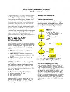
Compiling Data Flow Diagrams into Functional Programs Mikhail Auguston, Ravindra Mathur Department of Computer Science, New Mexico State University Las Cruces, NM 88003-0001, USA e-mail: {mikau, rmathur}@cs.nmsu.edu Abstract We suggest a method for compiling an arbitrary visual language V data flow diagrams with loops into a parallel functional language Sisal functions based on token propagation over the diagram and loop collapsing into a system of (mutually) recursive functions. This compilation algorithm preserves a concurrence potentially present in the data flow graph.
1
Introduction
The V visual data flow language [1] is an experiment with a visual representation of dependencies between data and processes and demonstrates how iterative control constructs could be visualized and adapted into a data-flow paradigm. The motivation behinds this is to achieve a clear and straightforward correspondence between the program source code (the data flow diagram in this case) and the order of program execution. In many cases an iterative algorithm description is preferable to recursive descriptions. The V language allows combinations of iteration and recursion. Data flow languages are closely related to functional paradigm. The aim of this paper is to present the methods for mapping a two-dimensional data flow diagram into a Sisal [6], [10], [11] parallel functional program. We have implemented a prototype compiler from V to Sisal. The advantage of choosing Sisal as a target language is in the fact that Sisal high-performance compilers and runtime systems are available on many of existing parallel computers.
2
Diagrams in V
A program in V is rendered as a two-dimensional data flow diagram that visualizes the dependencies between data and processes. The diagram defines the (partial) order of function calls and the data dependencies between function calls. The data flow diagram supports the possibility of par-
allel execution of threads within the diagram. This approach to Visual Programming Language design has became quite common in recent years, see e.g. [3],[5], [7], [8]. Diagrams may be nested, and actually are similar to the notion of procedures in common programming languages. Diagram calls may be recursive. The diagram corresponds to the notion of procedure in common programming languages. An instance of a diagram is activated when all input values are delivered to its input ports and all output values produced during the previous call are consumed by the input ports of the connected nodes downstream. A diagram does not retain any data items from the previous calls on its data flow.
3
Diagram collapsing algorithm
The aim of the diagram collapsing algorithm is to transform a two-dimensional data flow diagram into a set of function definitions with a main function which represents the diagram execution result and a number of auxiliary functions. In general, a diagram may have several input ports and several output ports. The Sisal function also can return multiple values. Diagram collapsing algorithm is based on token propagation along the diagram paths. A token represents a symbolic value in a certain place of the diagram resulting from the execution of the preceding diagram nodes. Initially tokens are placed at the diagram’s input ports and symbolic values associated with the tokens are formal parameter names. We’ll call a diagram with tokens associated with some node ports within it a configuration. The token propagation is complete when a token is associated with each output port. The symbolic value of this token yields the expression for the main function, i.e. the result of the diagram collapsing. Diagram collapsing is performed as a sequence of steps. A node in the diagram fires when all input ports of this node have tokens attached. As a result the input tokens are discarded and a resulting tokens are attached
2
VL98.doc
to the node’s outputs. This constitutes a single token propagation step. If in a certain configuration it is impossible to perform a propagation step, for instance, all diagram nodes have either empty either incomplete set of tokens at the input ports, the diagram collapses to the UNDEFINED value. We’ll consider in detail token propagation steps for different kinds of nodes that may appear along the path in the diagram.
4
Token propagation over a single node
First, let’s consider the token propagation over the operation node. An operation node has input and output ports to connect the operation with its input and output data and fires when and only when the following conditions are satisfied: •
all input values are delivered to the corresponding input ports;
•
all output values produced at the previous execution cycle are consumed by input ports of the connected nodes downstream. x F y
After the input tokens have been propagated through the operation node the configuration looks like: F F( x, y)
behavior when more than one token arrives on the input. x
x y
y
It is assumed that the merge node preserves the temporal order of data items arriving at its input ports (the order is nondeterministic if two or more inputs arrive "at the same time"). The fairness property guarantees that each input value will be processed. This implies that the merge node maintains a queue no longer that the number of input ports. To certain degree the merge notion may be considered as an analog of a place in Petri net [9]. Since the target language (i.e. Sisal in our case) is a deterministic one, the choice of a token to propagate will eliminate the nondeterminism. In this sense the function resulting from the diagram collapsing will not be equivalent to the original diagram. A conditional switch has several input ports (at the left side of the pictogram) and the same number of output ports on each of “True” and “False” sides. Some of output ports may be left unconnected. The Boolean Expression is evaluated and the flow of input values is switched either to the “True” or to the “False” side. Conditional node requires to collapse independently "True" and "False" paths and then to merge the results into a single if expression [10]. We’ll demonstrate it on the example of Maximum diagram. Note that not all output ports in conditional node may be used. x
Fork node propagates the token without changes. The fork node fires when it’s input port receives a value and all output values from the previous cycle are consumed by input ports downstream. To certain degree the fork notion may be considered as an analog of a transition in Petri net [9]. x x
x
x>y y
After the propagation along the "True" path and reaching the output port of the diagram the token has a symbolic expression x attached to it.
x>y
x
The merge node may present a nondeterministic
After the propagation along the "False" path and reaching the output port of the diagram the token has a
3
VL98.doc
symbolic expression y attached to it.
x>y
y
The whole diagram will be collapsed into the expression
for different stable loop configurations is introduced and the original diagram collapses into a system of (mutually) recursive functions. Since only a finite number of different token configurations is possible for the given diagram this loop collapsing process terminates after introducing a finite number of auxiliary functions. Example. A diagram that computes a factorial with an attempt to parallelize some threads [1].
if x > y then x else y end if Some or all output ports of a conditional node may be disconnected from the rest of diagram. The token propagation steps for "True" and "False" paths are still the same since the token propagation is global for the whole diagram and there may be other tokens in the diagram available for propagation.
5
Collapsing loops
Cyclic paths, or loops in the diagram should involve at least one node. We’ll mark all input ports that belong to some loop. Token propagation steps are performed until a configuration is reached where either a token arrives at each of the diagram output ports, either at some input port that belongs to a loop, either a token reaches an input port for some operation node and other input ports of this node are yet waiting for the input token to arrive. We’ll call such configuration stable. If in a stable configuration the output ports of the diagram are filled with tokens the diagram collapsing is completed.
The constant 1 value in the left lower corner is injected in the flow only once, at the beginning of the diagram execution. The initial configuration to start the diagram collapsing is the following.
N 1
If any of output ports is empty and there are not any more tokens at input ports that belong to a loop the diagram is collapsed into the value UNDEFINED, since no further token advance is possible. Suppose there are totally n tokens in the stable configuration t1, t2, ..., tn with symbolic values associated with them e1, e2, ..., en, correspondingly, and at least one of those tokens is at the input port of node belonging to a loop. We denote the result of diagram collapsing to be equal to the value of an auxiliary function F(e1, e2, ... , en). The function F(x1, x2, ..., xn) is defined as a result of collapsing a diagram starting in the same stable configuration with symbolic values x1, x2, ..., xn assigned to the corresponding tokens instead of e1, e2, ..., en. In order to collapse this diagram, tokens at input ports of some node belonging to a loop are propagated over this node. As a result a number of auxiliary functions providing the value
The first stable configuration is obtained after propagation of initial tokens to the input of a conditional node that belongs to a loop. N 1
1 We introduce an auxiliary function F(x, y, z) to denote the result of executing a diagram starting with this
4
VL98.doc
configuration. The diagram is collapsed to the following expression.
sion for collapsing the original diagram for F(x, y, z). F(x, y, z) = if x > 1 then
D( N ) = F( N, 1, 1 )
F(x-1, x*z, x*z )
Now the initial configuration for the auxiliary function F(x, y, z) should be collapsed.
else y end if Fine-grained parallelism present in the original diagram (x-- and x*z operations may be performed in parallel) is represented in the resulting functional program by independent actual parameters that could be evaluated concurrently.
x y
6
z Tokens are propagated over the conditional node that belongs to a loop. Two alternatives should be investigated. First we consider a configuration obtained from token propagation along the "True" path.
Compiling Iterative Constructs
The iterative pattern in V defines an iteration over a vector or over a row or a column within a matrix. x:
...
This pattern defines a vector traversal from left to right (from the elements with the smallest index values towards the largest index values). The current iterative item is given a temporary name x, which is visible downstream of the diagram in operation nodes immediately connected to the pattern node. Ellipses used in the iterative pattern make the iteration description more visible by providing the direction of the iteration.
x-1
x*z x*z Since the stable configuration reached is the same as previous, this diagram collapses to the expression F(x-1, x*z, x*z ) The second alternative provides the value for a diagram obtained after token propagation along the "False" path.
An iterative pattern in one data aggregate node and a data node in an another data aggregate node connected in the diagram are synchronized. This means that items in each of the aggregates are visited in the same order. The value of the second synchronized aggregate is constructed from the value of the first aggregate. Example. Select all odd numbers from a vector. This diagram is an analog of the list comprehension operation in functional languages like Miranda [4].
y
z This time the output port in the stable configuration contains a token with the value y. This provides a resulting expression for the whole configuration. Combining these two alternatives into a single expression yields an expres-
This V program may be translated into a Sisal loop
5
VL98.doc
expression.
expressions, and generates a Sisal program.
for X in Input returns array of X when odd(X) end for In order to collapse a diagram fragment with synchronized iterative construct the subdiagram with inputs at the iterative pattern data item and with outputs at the synchronized data node should be collapsed into an expression. x
D
...
...
If the result of collapsing the subdiagram D above is D(X) and if D(X) is defined for any X then the iterative construct is collapsed to the following Sisal loop expression. for X in Input returns array of D(X) end for In V subdiagram D may contain conditional nodes, loops, etc. Unfortunately, if D contains several conditional nodes with empty output ports, i.e. D(X) is defined not for all X, it becomes problematic to collapse the whole iterative construct into Sisal canonical loop expression with a single selection predicate P(X) for X in Input returns array of X when P(X) end for Nevertheless, it is straightforward to simulate Sisal’s loop expressions in V.
7
V to Sisal Compiler
The prototype of the V language has been designed in JAVA by Alfredo Delgado and Shridhar Bidigalu. The first version of a graphical editor and a simple interpreter supports only integer data type. The prototype core V to Sisal compiler was implemented using the Rigal [2] compiler writing language. It takes the file with the V diagram internal representation, converts it to the node graph, performs token propagation steps, collapses the diagram into Sisal
8
Conclusions
This paper presents a method to compile visual constructs into a parallel functional language for the core part of the visual language V. Although the Sisal target language has a number of iterative constructs for vector and matrix processing (loop expressions and array operations [11]) it appears that V iterative constructs are more general, and not all of them could be translated directly into Sisal loop expressions. We are much obliged to Daniel Cooke and Joe Pfeiffer for their kind support and suggestions during this work.
References [1] M. Auguston, A. Delgado, "Iterative Constructs in the Visual Data Flow Language", in Proceedings of the 13th International Symposium on Visual Languages, VL’97, IEEE Computer Society Press, 1997, pp. 152-159. [2] M. Auguston, Programming language RIGAL as a compiler writing tool, ACM SIGPLAN Notices, December 1990, vol.25, #12, pp.61-69 [3] E. Baroth, C. Hartsough, "Visual Programming in the Real World", in Visual Object-Oriented Programming, Concepts and Environments (ed. M. Burnett, A. Goldberg, T. Lewis), Manning 1995, pp.21-42. [4] R. Bird, P.Wadler, Introduction to Functional programming, Prentice Hall, NY, 1988. [5] P.T. Cox, F.R. Gilles, T. Pietrzykowski, "Prograph", in Visual Object-Oriented Programming, Concepts and Environments (ed. M. Burnett, A. Goldberg, T. Lewis), Manning 1995, pp.45-66. [6] J.-L.Gaudiot, W.Bohm, T. DeBoni, J.Feo, P.Miller, "The Sisal Model of Functional Programming and its Implementation", in Proceedings of pAs’97, Aizu-Wakamatsu, Japan, March 1997. [7] Glaser H., Smedley T., "PSH - the next generation of command line interface", in Proceedings of the 11th International Symposium on Visual Languages, VL’95, IEEE Computer Society Press, 1995, pp. 29-36. [8] T. D. Kimura, "Object-Oriented Dataflow", in Proceedings of the 11th International Symposium on Visual Languages, VL’95, IEEE Computer Society Press, 1995, pp.180-186. [9] J.Peterson, Petri net theory and the modeling of systems, Prentice-Hall, 1981. [10] S.Skedzielewski, "Sisal", in Parallel Functional Languages and Compilers, (ed. B.Szymanski), Addison-Wesley, 1991, pp.105-158. [11] S.Skedzielewski, J.Feo, P.Miller, S.Denton, "Sisal 90 User’s Guide", June 1995, Draft 0.95