Components for Embedded Software — The PECOS Approach Michael Winter1 , Thomas Genßler 1, Alexander Christoph1, Oscar Nierstrasz2 , St´ephane Ducasse 2 , Roel Wuyts2 , Gabriela Ar´evalo 2, Peter M¨uller3 , Chris Stich3 , and Bastiaan Sch¨onhage 4 1
continuously gather data, such as temperature, pressure or rate of flow. They process this data, and react by controlling actuators like valves or motors. A typical field device may contain a 16–bit microprocessor with only 256KB of ROM and 40KB of RAM.
[email protected], Forschungszentrum Informatik (FZI), Germany, http://www.fzi.de
2
[email protected], Software 3
Composition Group (SCG), University of Bern, Switzerland, http://www.iam.uinbe.ch/˜scg
[email protected], ABB Research Center, Germany, http://www.abb.com 4 Bastiaan
[email protected], Object Technology International (OTI), The Netherlands, http://www.oti.com
1 Introduction This paper presents a domain specific composition language called CoCo. The CoCo language has been developed in the context of the PECOS project 1 which aims at enabling component–based technology for a certain class of embedded systems called ”field devices”. CoCo is used in PECOS for the specification of components and for the composition of components to build entire field device applications. Besides this, CoCo allows the specification of architectural styles and system families and it supports compositional reasoning. The sequel of the paper is organized as follows: Section 2 gives a brief introduction to the application domain of field devices. In section 3, the PECOS component model is presented. Section 4 addresses the different aspects of the CoCo language mentioned above. Section 5 summarizes the ideas presented in this paper and points out future work.
2 Case study description ABB’s Instruments business unit develops a large number of different field devices, such as temperature–, pressure–, and flow–sensors, actuators and positioners. A field device is an embedded hard real–time system. Field devices use sensors to 1
Funded by the European Commission under IST Program IST-199920398 and by the Swiss government as BBW 00.0170. The partners are Asea Brown Bovery AG (ABB, Germany), Forschungszentrum Informatik (FZI, Germany), Object Technology International (OTI, The Netherlands), and Institut f¨ur Informatik und Angewandte Mathematik, University of Bern (UNIBE, Switzerland)
Fig. 1. Pneumatic positioner TZID
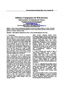
The software for a typical field device, such as the TZID pneumatic positioner shown in Fig. 1, is monolithic, and it has to be developed separately for each kind of field device. This results in a number of well–known problems: There is no or little code reuse and the software is hard to maintain, extend or customize. This is made even worse by the use of hard–coded, cyclic execution schedules. The goal of the PECOS project is to develop a model-centric CBSE process for embedded component software. This includes the definition of a component model, composition language and development environment, which support reuse of components and device architectures and provide support for (semi–)automatic schedule generation. 2.1 Example Application We will use the following example throughout this paper to illustrate the PECOS component model and composition language. Part of the PECOS case study is concerned with setting a valve at a specific position between open and closed. Fig. 2 illustrates three connected PECOS components that collaborate to set the valve position; the desired position is determined by other components not shown here. In order to set and keep the valve at a certain position, a control loop is used to continuously monitor and adjust the valve. – The ModBus component works as an interface to a piece of hardware called the frequency converter, which determines the speed of the motor. The frequency to which the motor should be set is obtained from the ProcessApplication component. ModBus outputs this value over a serial
Fig. 2. FQD control loop
line to the frequency converter using the ModBus protocol. – The FQD (Fast Quadrature Decoder [2]) component is responsible for capturing events from the motor. This component abstracts from a micro–controller module that does FQD in hardware. It provides the ProcessApplication with both the velocity and the position of the valve. – The component ProcessApplication obtains the desired position of the valve (Set–Point) and reads the current state of the valve from the FQD component. This information is then used to compute a frequency for the motor. Once the motor has opened the valve sufficiently, ascertained by the next reading from the FQD, the motor must be slowed or stopped. This repeated adjustment and monitoring constitutes the control loop.
precise about what we mean by a component. In particular, we must take care to specify how components are structured and composed, which properties of components are important to capture and reason about, and how a composition of components can be interpreted at run–time.
Besides the tight resource situation, there are additional key issues concerning the field device domain: (1) Cyclic behavior — each component is responsible for a single piece of functionality, which is repeatedly executed (with a specified cycle time) and must not take longer than a specified worst–case execution time. (2) Data–flow–oriented interaction — components communicate by sending or receiving data. The interface of a component consists of a set of data ports. (3) Threading — some components are passive (i.e., cyclically invoked by a scheduler), while others (like FQD) have their own thread of control in order to react on asynchronous events or to perform long computations in the background.
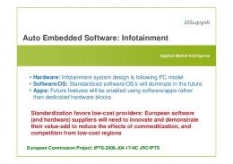
Fig. 3. A Component Model for Embedded Software
Here we briefly present a meta–model that reflects an architectural style [10] for embedded systems software. We also sketch how compositions of components can be interpreted by means of Petri nets. 3.1 Model Elements Fig. 3 illustrates the key elements of the component model. Components have interfaces defined by a number of ports, and may be hierarchically composed. So–called leaf components are treated as black boxes, and are directly implemented in some host programming language. Composite components, on the other hand, are built by connect-
3 A Component Model for Embedded Software In order to apply component–based software development to embedded systems software, we must be 2
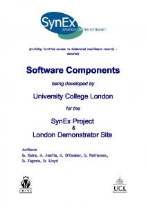
ing the ports of other, existing components (leaf or composite), and expressing which ports of the constituent components are exported as ports of the composite (See Fig. 4.) Ports are shared variables that allow components to communicate with each other. Connected ports and exported ports therefore represent the same variable. Connectors may only connect ports of compatible type, direction and range. The model expresses three kinds of components relevant for embedded systems.
exported port
composite component
leaf components
connected ports
Fig. 4. A Composite Component
Active Components (e.g., ModBus in figure 2) have their own thread of control. Active components are used to model ongoing or long–lived activities that cannot complete in a short cycle– time. A complete system composed of components is always modeled as a composite active component. Composite active components schedule their constituent components in order to meet the deadlines imposed by the real–time constraints. Passive Components (e.g., ProcessApplication) have no own thread of control. They are used to encapsulate a piece of behavior that executes synchronously and completes in a short cycle time. Passive components are scheduled by the nearest active parent that contains them. Event Components (e.g., FQD) are components whose functionality is triggered by an event. They are typically used to model hardware elements that periodically generate events. Typical examples are timers, used to keep track of deadlines, or devices that emit events encoding status information, such as the current rotation speed of a motor, the current temperature, and so on.
data–flow between components (esp. between components that live in different threads of control) and Timing — how to make sure that component’s functionality is executed according to cycle times and required deadlines. A composition of components has as many threads of control as there are active components. Each active component is responsible for scheduling the passive components under its control. We formalize the execution semantics by means of a Petri net interpretation. The details of this formalization, however, are beyond the scope of this paper. They are described in [7, 5].
4 The CoCo Language In this section we introduce the component composition language CoCo. It is the syntactical representation of the component model described in section 3, enhanced with additional features. The language is intended to be used for 1) the specification of components, 2) the specification of entire field device applications as compositions of components 3) the specification of architectures and system families. In addition, CoCo supports reuse of components and architectures and supports compositional reasoning. Last but not least, CoCo serves as input for scheduler computation and code generation. In the sequel, we present these different aspects of the language. First, we describe how developers can specify components in terms of their interfaces. Then, we describe how components are composed to build composite components and show how CoCo supports the specification of system families. Finally, we sketch how CoCo specifications can be used for reasoning about functional and non– functional properties of a system.
All three kinds of components can be composite. Components are characterized by their properties, which encode information such as timing and memory usage. 3.2 Execution model In addition to the static structure described above, the PECOS model has an execution model that describes the behavior of a Field Device. By using Petri nets [12] to represent the execution model, we intend to reason about real–time constraints and automatically generate real–time schedules for software components. The execution model deals with the following two issues: Synchronization — how to synchronize 3
4.1 Specifying Components in CoCo
The only information available about this implementation is the worst–case execution time it takes to perform the computation (property execTime) and the interval between these computations (property cycleTime). These values are specified in CoCo as component properties. Properties serve to attach functional and non– functional features to a component, such as init values for ports, memory consumption and worst–case execution time. They can be structured in so–called property bundles. These bundles group properties that semantically belong together, such as scheduling information (worst–case execution time, cycle time). Properties can be used by tools to inspect the component in different phases of the development process (e.g., when generating a scheduler). Properties can be set on a per–component basis and a per–instance basis.
Components represent units of computation and are the major means of structuring a CoCo system. CoCo supports all component types of the component model. For example, Figures 5 and 6 show a CoCo specification of our recurring example. There we see an active component (marked with the keyword active), an event component (keyword event) and two passive components. In analogy to the OO model, components play the role of classes. That means, they define a type and scope in the same sense as OO classes do. Components can be instantiated that is, one can create an instances of a component with a unique identity. But in contrary to object instances, components can not be instantiated dynamically at run–time, but all instances are statically known.
4.2 Composing Components with CoCo
event component FQD f output float actualPosition; output float velocity; property cycleTime = 100; property execTime = 10;
Components are composite when they contain instances of other components (see for example the component PositionValve in Fig. 6). In PECOS, an entire application, such as a field device, is modeled as a composite component. Instances of components have a component type and a unique name within the scope of the enclosing component. All instances are created at system start–up, that is there is no ”new” statement to dynamically create instances during run–time but all possible instances are known at compile–time. This allows for a number of checks at compile–time as well as for automated scheduler generation.
g
active component ModBus f input float setFrequency; property cycleTime = 100; property execTime = 10;
g
component ProcessApplication f input float setPoint; input float actualPosition; input float velocity; output float setFrequency; property cycleTime = 100; property execTime = 20;
g
Fig. 5. The FQD control loop components specified in CoCo
component PositionValvef ModBus mb; FQD fqd; ProcessApplication pa;
Programming in CoCo is data–flow–oriented. Ports (e.g., setPoint) denote data flow into or out of a component and are the only means of using a component. Ports are assigned both a data flow direction (input, output, or in–/output) and a data type. A component’s interface does not contain any functions that my be called, but one may think of a component as a piece of functionality that is executed cyclically (passive component) or in response to a certain event (event component) in order to compute output values depending on the current input values and/or the internal state of the component. The actual behavior, however, is not specified at the level of CoCo specifications but hidden in the implementation of the component.
input float setPoint;
g
connector c1 (setPoint, pa.setPoint); connector c2 (fqd.actualPosition, pa.actualPosition); connector c3 (fqd.velocity, pa.velocity); connector c4 (pa.setFrequency, mb.setFrequency);
Fig. 6. The FQD (Fig. 2) control loop itself specified in CoCo
Connection of components is achieved through the use of connectors (e.g., connector c1 in component PositionValve). Connectors connect a list of ports defined either in the current component (like 4
port setPoint in connector c1) or by one of the contained instances (that is, instances in the same scope). Different connectors that share a common port represent the same connection. A special case of this rule is at the border of composite event and active components: as theses components execute in their own thread of control, data only bypasses their borders during a synchronization step.
AbstractProcessApplication again is an abstract component that defines a certain interface (i.e., ports, properties) every process application component has to conform to. Thus, roles serve as placeholders for instances. These placeholders can also be connected by connectors as if they were normal instances. This way a developer is able to specify an entire family of applications that share a common architecture in terms of the components involved and their data–flow dependencies. To create a specific member of this family, a component has to implement the respective abstract component. Implementing an abstract component means that all roles defined by this abstract component have to be bound to suitable instances and that all connectors, instances, ports, and properties defined in this abstract component become now part of the implementing component. In our example the role PecosPA is bound to an instance of component ProcessApplication. The component ProcessApplication on the other hand is required to implement the abstract component AbstractProcessApplication.
4.3 Specifying software families with CoCo Components serve to specify concrete pieces of a system. But it is often desirable to be able to specify architectural styles or families of components or families of entire applications (devices). CoCo provides the concept of abstract components for this purpose. By means of abstract components one can specify a template of a system that can later be filled in with concrete components. Abstract components do not have a representation in the model as they do not contribute to the run–time behavior of field device software. They are merely a technique to simplify specification and to enable the reuse of designs.
4.4 Composition checking In this section we briefly sketch how compositions can be reasoned about. In order to make a composition valid, certain rules must be followed. There are simple syntactic rules and rules originating from the static semantics of CoCo which are checked by the composition language compiler.These rules express requirements, that emerge from the component model. Examples for such rules are “if a component implements an abstract component, it must bind all roles” or “all mandatory ports must be bound”, etc. In addition we allow the specifaction and checking of company-, product-line- or product-specific semantic rules. We employ first-order predicate logic for this purpose. The PECOS composition tool is able to generate a database of Prolog facts out of a composition specification. These facts describe the whole system, together with all included components, their ports, properties, and connections. Semantic rules are formulated as Prolog queries (or in the form of Horn clauses) and are checked against the generated facts. For example, Fig. 8 shows the Prolog facts, which have been generated for the CoCo specifications of Fig. 5. An example query is shown in Fig. 9. It defines the Prolog rule validScheduleInfo which checks, if every component has got the execTime and cycleTime properties specified.
abstract component PecosControlLoopf role AbstractProcessApplication PecosPA; role AbstractControlDevice PecosCtrl; role AbstractFeedBackDevice PecosFdbck; input float setPoint;
g
connector setPoint(setPoint, PecosPA.setPoint); connector feedback1(PecosPA.actualPosition, PecosFdbck.actualPosition); connector feedback2(PecosPA.velocity, PecosFdbck.velocity); connector control(PecosPA.setFrequency, PecosCtrl.setFrequency);
[...] component PositionValve is PecosControlLoopf ProcessApplication pa is PecosPA; ModBus mb is PecosCtrl; FQD fqd is PecosFdbck;
g
Fig. 7. Using abstract components to specify system families
Besides the elements known from normal components, abstract components can define so–called roles. Roles are typed variation points or holes in a (micro–)architecture. Fig. 7 shows the specification of an architectural style for control loops. We assume that a PecosControlLoop should always have an instance of sub–type of AbstractProcessApplication that plays the role PecosPA in our valve controller architecture. 5
% Component FQD component(’FQD’, ’event’). property(’FQD’, ’optional’, ’cycleTime’, ’100’). property(’FQD’, ’optional’, ’execTime’, ’10’). port(’FQD’, ’optional’, ’output’, ’float’, ’actualPosition’). port(’FQD’, ’optional’, ’output’, ’float’, ’velocity’). % Component ModBus component(’ModBus’, ’active’). property(’ModBus’, ’optional’, ’cycleTime’, ’100’). property(’ModBus’, ’optional’, ’execTime’, ’10’). port(’ModBus’, ’optional’, ’input’, ’float’, ’setFrequency’). % Component ProcessApplication component(’ProcessApplication’, ’passive’). property(’ProcessApplication’, ’optional’, ’cycleTime’, ’100’). property(’ProcessApplication’, ’optional’, ’execTime’, ’10’). port(’ProcessApplication’, ’optional’, ’input’, ’float’, ’setPoint’). port(’ProcessApplication’, ’optional’, ’input’, ’float’, ’actualPosition’). port(’ProcessApplication’, ’optional’, ’input’, ’float’, ’velocity’). port(’ProcessApplication’, ’optional’, ’output’, ’float’, ’setFrequency’).
classes, component instances map to statically initialized instance variables, and connectors represent shared instance variables in the enclosing object. Ports map to set– and get–methods that read from or write to these shared instance variables, as determined by the connectors. This code generation from CoCo specifications needs to pay special attention to efficiency — measured both in execution time and in memory consumption, because of the requirements imposed by the field device domain. More information on these issues can be found in the relevant PECOS deliverable [9].
5 Related work Several approaches to the composition of software from components have been proposed in the literature. An important contribution to this topic stems from the field of software architecture systems [3, 10, 4]. A recent survey is given in [6]. Architecture systems introduce the notion of components, ports, and connectors as first class representations. However, most of the approaches proposed in the literature do not take into account the specific properties of software systems for embedded devices. In [8] van Ommering et.al. introduce a component model that is used for embedded software in consumer electronic devices. Koala components may have several ”provides” and ”requires” interfaces. Each of this interfaces defines ”ports” in the sense of methods. In order to generate efficient code from Koala specifications, partial evaluation techniques are employed. However, Koala does not take into account non-functional requirements such as timing and memory consumption. Koala lacks a formal execution model and automated scheduler generation is not supported. In [11] a framework for dynamically reconfigurable real-time software is presented. It is based on the concept of so called Port Based Objects. The framework provides only a limited form of specifying a component (e.g., only rudimentary scheduling information is given, predefined port types). Furthermore the architecture is limited i.e., there is no support for composite components. The verification of a composition regarding non-functional properties such as memory consumption and schedulability is lacking too.
Fig. 8. The Prolog facts for the components of Fig.5 hasProperty(X, Y):component(X, Z1), property(X, Z2, Y, Z3). hasExecTime(X):hasProperty(X, execTime). hasCycleTime(X):hasProperty(X, cycleTime). scheduleInfo(X):hasExecTime(X), hasCycleTime(X). validScheduleInfo:forall(component(X), scheduleInfo(X)).
Fig. 9. Example Prolog query
Other examples for this type of rules are fulfillment test of specific requirements for debugging, release versions of the software, dependencies between components, platform specific property settings, such as in “...in this product line, a particular type of components must always be used together with another particular component type...´´. 4.5 Code Generation: from CoCo to C++ and Java As already mentioned, the behaviour of a PECOS component is not specified in CoCo, but it is directly implemented in a target language. Therefore, a system specified in CoCo is mapped into a class hirarchy in the target language. This hirarchy corresponds directly to the hirarchical component structure of the CoCo specification: Components map to
6 Summary In this paper, we have presented the domain specific composition language CoCo as part of the PECOS 6
project. The two main characteristics of the language are its data–flow oriented composition style and the support for non–functional properties (most importantly timing information as input for schedule generation). The different purposes of CoCo have been presented: it serves for defining component interfaces and composite 2 components. Furthermore, it has been shown, how CoCo allows to define system architectures in the form of abstract components. Finally, it has been indicated, how compositional reasoning is supported and how the mapping from CoCo to C++ and Java is handled. In order to prove the usefulness of the CoCo language, ABB is currently carrying out a number of case–studies. One of these has been sketched in section 2. In order to facilitate the application of the PECOS approach, tool support for CoCo has been developed. A first prototypical implementation of a development environment has been carried out which groups together a CoCo editor, the code generator for C++ and Java as well as the Prologe fact generator. Currently, a more sophisticated implementation in form of an Eclipse [1] plug–in is under develpment which will integrate further project management facilities like ressource and version control.
8. Rob van Ommering, Frank van der Linden, Jeff Kramer, and Jeff Magee. The koala component model for consumer electronics software. IEEE Computer, 2000. 9. Bastiaan Sch¨onhaage. Model mapping to C++ or Java-based ultra-light environment. Technical Report Deliverable D2.2.9-1, Pecos, 2001. www.pecosproject.org. 10. M. Shaw and D. Garlan. Software Architecture – Perspectives on an Emerging Discipline. Prentice Hall, 1996. 11. David B. Stewart, Richard A. Volpe, and Pradeep K. Khosla. Design of dynamically reconfigurable realtime software using port-based objects. IEEE Transaction on Software Engineering, 23(12):pages 759– 776, 1997. 12. Jiacun Wang. Timed Petri Nets. Kluwer Academic Publishers, 1998.
References 1. Eclipse project home page. 2. Fast Quadrature Decode TPU Function (FQD). Semiconductor Motorola Programming Note. TPUPN02/D. 3. Robert Allen and David Garlan. A formal basis for architectural connection. ACM Transactions on Software Engineering and Methodology, 6(3):213– 49, July 1997. 4. Paul C. Clements. A survey of architecture description languages. In Int. Workshop on Software Specification and Design, 1996. 5. St´ephane Ducasse and Roel Wuyts (editors). Fielddevice component model. Technical Report Deliverable D2.2.8, Pecos, 2001. www.pecos-project.org. 6. Ariel D. Fuxman. A survey of architecture description languages. 7. O. Nierstrasz, S. Ducasse, R. Wuyts, Gabriela Ar´evalo, A. Black, P. M¨uller, C. Zeidler, T. Genssler, and R. van den Born. A component model for field devices. In To Appear: Second Conference on Component Deployment, 2002. 2
As we have seen, entire PECOS applications are a special case of those.
7