these networks are best represented by dynamic graph models. To cope with ...... is represented by the CGI data structure and the vertices actual data are stored.
(IJACSA) International Journal of Advanced Computer Science and Applications, Vol. 7, No. 2, 2016
Comprehensive Survey on Dynamic Graph Models Aya Zaki
Mahmoud Attia
Faculty of Computer and Information Science Ain Shams University Cairo, Egypt
Faculty of Computer and Information Science Ain Shams University Cairo, Egypt
Abstract—Most of the critical real-world networks are continuously changing and evolving with time. Motivated by the growing importance and widespread impact of this type of networks, the dynamic nature of these networks have gained a lot of attention. Because of their intrinsic and special characteristics, these networks are best represented by dynamic graph models. To cope with their evolving nature, the representation model must keep the historical information of the network along with its temporal time. Storing such amount of data, poses many problems from the perspective of dynamic graph data management. This survey provides an in-depth overview on dynamic graph related problems. Novel categorization and classification of the state of the art dynamic graph models are also presented in a systematic and comprehensive way. Finally, we discuss dynamic graph processing including the output representation of its algorithms. Keywords—dynamic graphs; evolving graphs; temporal graphs; data management
I.
networks;
evolving
I NTRODUCTION
Most real-world networks like social networks [1], [2], [3], wireless networks [4], transportation networks [5], and other networks contain a vast amount of information. These networks are mostly represented by graphs. These graphs model the network entities and their relations in the form of vertices and edges respectively. The majority of current network graph representations rely on static graphs. Such type of graphs fails to handle the real-time changes of networks. That’s why there is a significant interest in providing a dynamic graph model that stores the network historical changes and gives the ability to query these changes [6]. Temporal Relational Database ”TRD” shares the power of storing historical changes with dynamic graphs. A lot of literature on TRD focus on temporal data model and temporal query language [7], [8], [9], [10], [11], [12], [13]. The two main basic concepts of TRD are valid time and transaction time. Valid time represents the time period that indicates when the fact is true in the real world. Transaction time represents the time period of storing and removing the fact from the DB. In this survey, we focus on valid time, where the goal is to retrieve the graph entities that are valid at any given time instant. We start off by reviewing the main issues of dynamic graphs: temporal evolution and dynamic graph queries, as well as their related terminologies. Then, we present an overview to categorize the existing dynamic graph models proposed by other researchers. Finally, we provide a brief survey on processing including both: dynamic graph algorithms and output
Doaa Hegazy and Safaa Amin Faculty of Computer and Information Science Ain Shams University Cairo, Egypt
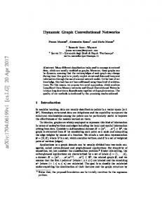
representation. Fig 1 summarizes our proposed classification of the accomplished work in dynamic graphs. The rest of this paper is organized as follows: Section 2 provides an overview about how dynamic graphs evolve with time. In section 3, we present a study of dynamic graph queries. Section 4 categorizes the existing dynamic graph models. Section 5 states the output representations of dynamic graph algorithms and overviews some of the most important graph problems. Finally, Section 6 concludes this paper and discusses the future research plans. II.
T EMPORAL E VOLUTION
Temporal evolution shows how dynamic graphs evolve with time and the changes that happen to its components. This type of evolution can be categorized into two categories: topological evolution and attributes evolution, which will be discussed in details in the following subsections II-A and II-B. A. Topological Evolution A dynamic graph undergoes continuous changes with time in its structural components: nodes and edges. Such changes are called topological evolution. Due to the topological evolution, the graph structure is reshaped based on the following: . Edge Evolution: dynamic graph changes related to its edges only. These changes can be represented by the actions: add edge or remove edge. In some cases, the evolution of a network is modeled by edge evolution only, where the network nodes are constant over time [14]. . Node Evolution: dynamic graph changes related to its vertices only. These changes can be represented by the actions: add node or remove node. Contrary to edge evolution, there are no cases where a networks evolution is modeled by node evolution only. Most networks that have topological evolution, involve both edge evolution and node evolution [13]. In these networks, when a remove node action occurs, both the out and in edges of the removed node are implicitly removed from the graph before the removal of the node itself. B. Attributes Evolution Dynamic graph continuous changes occur on graphs attributes (i.e., internal attributes of nodes and edges) and do not affect the graph topology. 573 | P a g e
www.ijacsa.thesai.org
(IJACSA) International Journal of Advanced Computer Science and Applications, Vol. 7, No. 2, 2016
Dynamic Graphs
Query
Temporal Evolution Topological Evolution Edge Node
Attribute Evolution
Models
What to Time Node query granularity granularity Topology Attributes
Edge Node
Single Time Point Multiple Time Points
Node Centric
Notion of time
Modeling categories
Discrete Continuous
System Centric
Output Representation of Algorithms
Sequence of Snapshots Whole Graph Log File
Time Interval
Distributed Graph over Servers
Time Expression
Single Dynamic Solution Multiple Static Solutions Multiple Dynamic Solutions Single Aggregated Solution
Fig. 1: Dynamic Graphs
. Edge Attributes Evolution: dynamic graph changes related to its edges attributes. These changes can be represented by the actions: add attribute value, remove attribute value or update attribute value [15]. . Node Attributes Evolution: dynamic graph changes related to its node attributes. These changes can be represented by actions similar to edge attributes evolution [16]. According to this classification, the evolving graphs have two types: fully evolved dynamic graphs and partially evolved dynamic graphs. Fully evolved dynamic graphs have both topological and attributes evolution in edges and nodes. In contrast, partially evolved dynamic graphs have a partial mix of them. III.
Q UERY
In this section, the query operators that have been proposed in the literature of dynamic graphs are presented. We provide a novel classification based on three criterions that will be detailed in the following subsections. A. What to query According to the interest of applications, we classify the query functionality on dynamic graphs into two classes: . Topology: includes queries that ask about historical graph structure. In other words, queries are asking about nodes and edges of the graph at a previous time. For example, querying a node neighbors ”retrieve friends of Jon at Oct 10, 2000” [17].
. Attributes: in this class, queries are used to retrieve a graph components attributes by asking about nodes attributes or edges attributes at a previous time. For example, querying the sent packets from node A to node B ”retrieve packets that are sent from A to B at Oct 10, 2014” [15].
B. Time granularity Dynamic graph queries differ from static graph queries because of the inclusion of the time dimension. The time dimension has several forms, which are classified into four types as follows: . Single Time Point: where query is used to ask about graph historical information valid at a specific time point. For example ”retrieve the graph structure at Oct 10, 2000 [18]. . Multiple Time Points: this query is asking about retrieving graph historical information that is valid at multiple time points. For example ”retrieve the graph structure at every monday between 2000 and 2005 or ”retrieve Jon friends at Oct 10, 2000 and Dec 24, 2003” [19]. . Time Interval: this type of query has more complex form. It is asking about graph historical information valid at an interval of time. For example ”how does the average number of Jon friends change over [2000, 2005]” [19]. . Time Expression: in which, a boolean expression is applied over a set of multiple discrete point. For example, ”retrieve Jon friends that are valid at (2000∧¬2001)” [19]. 574 | P a g e
www.ijacsa.thesai.org
(IJACSA) International Journal of Advanced Computer Science and Applications, Vol. 7, No. 2, 2016
C. Node granularity The third criterion that distinguishes dynamic graph queries is the node granularity classified into two types: . Node-Centric Queries: involve one or more graph node related to a specific node. In other words, these queries need to access a part of the graph. For example, retrieve friends of Jon at Oct, 10, 2009 [17]. . System-Centric Queries: are also known as Global Queries. These queries involve all graph nodes. For example, compute the graph diameter at Oct 10, 2008 [19]. IV.
M ODELS
A dynamic graph model is a mapping Gt = (V, E) that yields the state of the graph (i.e., the set of nodes and set of edges) at a given time instant t. Both directed and undirected dynamic graphs can be represented by most of the existing discrete and continuous models. In a discrete model, snapshots are taken periodically at every fixed time period (e.g., every 30 minutes, every day, and every week). This type of model provides complete accurate mapping at specific time instants and gives the nearest state (e.g., time-based, changes-based) at any other instant. On the other hand, the continuous model keeps track of all changes by representing every one of them. Therefore, it can map every instant into a completely accurate valid graph state. In the following subsections, we classify the relevant literature into four categories, and describe each one of them. A. Dynamic Graph Models Categorization The existing dynamic graph models that were proposed by other researchers can be categorized into four basic categories: . Sequence of Snapshot: the graph historical changes are stored as a sequence of snapshots. Each snapshot represents the graph state at a single instant of time. The snapshot consists of a set of vertices V and a set of edges E. However, the existing models in this category are discrete. . Whole Graph: the graph historical changes are stored as one large graph. The changes (i.e., vertex/edge deletion, vertex/edge insertion and their attributes updates) are applied and stored in the same graph. Moreover, each graph element (i.e., vertex, edge or attribute) is accompanied with a valid time point or valid time interval according to its model. Models of this category are either discrete or continuous. . Log File: the latest snapshot as well as key snapshots are kept while the graph historical changes between any two consecutive key snapshots are stored in a log file. Each log file is accompanied with its valid time interval. The existing models in this category are continuous. . Distributed Graph over Servers: dynamic graph distribution can be categorized based on two parameters: . Time: divides the graph historical changes according to time over a set of servers. Each server is responsible for a period of time. . Structure: divides the graph structure (e.g., vertices distribution) over a set of servers. Each server is responsible for managing its vertices by storing and retrieving their historical changes.
This survey discusses distributed graph over servers from a structural perspective. Thats because the distribution based on time can be merged with any of the other categories as an improvement, without affecting the management (i.e., storing and retrieving) of the used model of the merged category. In contrast, distribution based on structure affects the management of the used model of the merged category. B. Sequence Of Snapshots Varieties of this category have been proposed in Rossi’s model[20], FVF[21], and Yang’s model[14]. This category models dynamic graphs as a sequence of snapshot G[t1 ,tn ] = {G1 , G2 , G3 , ..., Gn }. Each snapshot Gi is a static graph that represents the valid state of the dynamic graph at time point ti . The snapshot is represented by a triple < Vi , Ei , ti > and is stored by its time point ti . Storing sequence of snapshots naively as in Yang’s model[14], and Rossi’s model [20] would clearly require a prohibitively large storage. FVF[21] proposes Find Verify and Fix ”FVF” framework which takes sequence of snapshots that are produced in a compressed storage model as input. This compressed storage model stores a set of key snapshots and the associated set of deltas. The set of key snapshots is intended to be much smaller than the original set of all snapshots. A set of deltas stores only changes that are needed to completely construct a snapshot from its related key snapshot by merging the key snapshot with the proper delta. In FVF, the sequence of snapshots is divided into clusters based on similarities among them. Each cluster has two representative graphs (G∪ and G∩ ), where G∩ is the largest common sub-graph of all snapshots in the same cluster, and G∪ is the union of the smallest sub-graphs of all snapshots in the same cluster. FVF needs to access the two representative graphs of the Gi ’s cluster as well as the snapshot Gi itself for answering a query (e.g., node-centric) on Gi snapshot. Compressed Storage Models ”SM” have been discussed in FVF[21] for storing these clusters. However, the most efficient one is called SM-FVF. It saves four deltas for each cluster C, which has k snapshots. . First, D(G∩ , GP ∩ ): the needed edges to be inserted or deleted from GP ∩ to get G∩ , where the GP ∩ is the G∩ of the previous cluster. . Second, 4(G∪ , G∩ ): the set of edges that exists in G∪ and does not exist in G∩ . . Third, 4(G1 , G∩ ): the set of edges that exists in G1 and does not exist in G∩ . . Finally, D(Gi , Gi−1 ), ∀ 2 < i < k: the needed edges to be inserted or deleted from Gi−1 to get Gi . Resulted storage of one cluster can be computed as in (1). SM − F V F (C) = {D(G∩ , GP ∩ ), 4(G∪ , G∩ ), 4(G1 , G∩ ), D(Gi , Gi−1 ), ∀2 < i < k}[21] (1) The SM-FVF compressed model has no redundancy among delta files of the same cluster, but it has redundancy among delta files of different clusters. This redundancy is ignored relatively to the naive model which has a lot of redundant 575 | P a g e
www.ijacsa.thesai.org
(IJACSA) International Journal of Advanced Computer Science and Applications, Vol. 7, No. 2, 2016
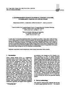
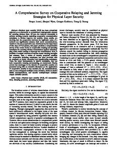
data among its sequence of snapshots. A downside of this compressed model is that it needs to access [G1∩ , G(i−1)∩ ] for constructing G∩i . Therefore, it is suitable for queries that need to be applied over the whole sequence of snapshots. We suggest replacing the delta file D(G∩ , GP ∩ ) of each cluster i with a delta file that contains Gi∩ edges and vertices for improving queries that need to access only one snapshot or few snapshots. Evaluating a snapshot Gt is straight forward procedure in sequence of snapshots category. It is done by either finding the exact time point t or the nearest time point to it in order to return its associated pair < V, E > in the naive model or by constructing it in the compressed model. In conclusion, the compressed model in FVF[21] is more efficient with regard to the used storage than the naive model described by Yang[14], and Rossi[20]. However, the naive model is faster than the compressed model in query performance due to the consumed construction time in the compressed model. C. Whole Graph In this category, dynamic graphs is modeled as one large graph G[t1 ,tn ] = < V[t1 ,tn ] , E[t1 ,tn ] >, where V[t1 ,tn ] and E[t1 ,tn ] are set of all vertices instances and edges instances respectively. Alternatives of this category have been proposed in koloniari’s model1 [22], Huo’s model[23], [24], TPM[25], FSDNs[15], and Evo-graph[16]. Dynamic graphs in this category can be basically represented as a two sets methodology: vertices set and edges set as models presented by koloniari in [22], and Huo in[23], [24]. Each element of the edges set and the vertices set can be represented as a triplet < srcID, desID, [ts , te ] > and < vID, {att}, [ts , te ] > respectively, where the accompanied interval [ts , te ] represents only one valid interval. This methodology has downsides in its storage by storing the same element multiple times with different valid time intervals which happens in case of an element existence and re-existence. Alternatively, the temporal provenance model ”TPM” [25] provides another representation of the two set methodology. Each vertex of the vertices set can be either entity instance with a triplet < vID, {att}, ts > or timed folder/path node with a triplet < vID, {att}, (ts , d) >. Timed folder node and timed path node are containers that are used for storing queries results. Each edge of the edges set represents a relationship between two vertices and it does not have any time notion. Fig. 2 provides more information about vertices and edges notions of the TPM (i.e., the relation types as well as the entities types). TPM suffers from a number of drawbacks regarding to storage that are concluded a follows:. TPM Stores redundant vertices. For example, when an entity starting connection with another entity, new two vertices are created corresponding to them with new IDs and the same data. . Some results of queries are stored also in the same graph as Path/Folder nodes which increase the graph size. The two set methodology drawbacks are avoided in Fixed Schedule Dynamic Networks ”FSDNs”[15]. The paper proposes a data structure that allows storing only the new valid
time interval deduced from the re-existence rather than restoring the whole elements. The data structure consists of set of vertices, where every vertex element is a triplet < vID, I, {N eighbor} >. The vertex contains a set of its valid time intervals I as well as a set of its neighbors. Each neighbor is a triplet < nID, I, att >, where the set I represents valid time intervals of this neighbor’s connection. This data structure has downsides regarding to its storage by storing each edge twice (i.e., once at each end point vertex). However, in both methodologies, element intervals do not intersect. Furthermore, there are models in the whole graph category that not only store the historical changes of dynamic graphs but also, store the types of changes themselves like Evograph [16]. The Evo-graph model states the vertices versions of dynamic graphs and the types of changes themselves that produced these versions. Evo-graph consists of two interconnected components: data-graph and change-graph. Data-graph comprises all vertices versions of the actual data. Each data vertex version is a pair< vID, {att} > and is connected to another data vertex by data-graph edge. The change-graph contains the change types that produce new vertices’ versions in data-graph as shown in Fig. 3. Each change-graph vertex is a triplet < vID, changeT ype, timeStamp > and is connected to another change vertex by a change-graph edge. Evo-graph components are connected by evolution edges. An evolution edge connects two data-graph vertex versions (i.e., before and after a change operation) with a change-graph vertex (i.e., the change operation itself). The Evo-graph model suffers from a number of drawbacks, the main of such drawbacks can be summarized as follows:. It is not applicable for all graph networks due to its structure . Regarding to storage, the same vertex is stored several times using any type of change except the update type as shown in Fig. 3. Retrieving a snapshot Gt in the whole graph category is costly because the search space is the whole graph. The snapshot is evaluated by traversing the whole graph elements to capture its valid elements only at time t. The valid element at time t is an element whose time point is t or its time interval contains t. Huo’s model [23], [24] proposes a temporal partitioning for improving time point query performance. However, the node-centric query is efficient in FSDNs[15] due to its data structure, where a node is selected then the search is expanded to its neighbors list. In temporal partitioning, the whole graph time interval is distributed over partitions. For example, given n time instants and the fact that each partition can have m time instants, then [n/m] partitions will be generated. Edges and vertices that have overlapped time intervals over more than one partition will be duplicated in these partitions. While this duplication allows time point query to access one partition rather than accessing the whole graph, it increases the TPM storage size. On the other hand, this portioning makes the small time interval query access two partitions in the worst case. Therefore, Huo in [24] applies overlapped partitioning for improving the performance of the small interval query and reducing the number of accessed partitions. However, the overlapped partitioning consumes more storage (i.e.., 50% overlapping will lead to 100% redundancy). 576 | P a g e
www.ijacsa.thesai.org
(IJACSA) International Journal of Advanced Computer Science and Applications, Vol. 7, No. 2, 2016
Fig. 2: Temporal Provenance Model notions [25]
Fig. 3: Effect of snap change operations on the Evo-graph [16]
In conclusion, it is found that FSDNs[15] is the most efficient model in the used storage but, Huo’s model [23], [24] is the most efficient model in query performance due to the overlapped partitioning. D. Log File The main idea of this category is based on materialization, which is a process of storing a set of dynamic graph snapshots and delta log files between them. Varieties of this category have been presented in Koloniari’s model2[19], [17], Khurana’s model [18], and Chronos[26]. This category models dynamic graphs as G[t1 ,tn=crr ] = < Gtcrr , L, M >, where Gtcrr is a snapshot that represents the current dynamic graph state, L is a set of log files L = {L1[ts1 ,te1 ] , L2[ts2 ,te2 ] , ..., Ln[tsn ,ten ] }, each representing the historical changes, which occurred during its associated time interval [tsi , tei ] and M is set of materialized snapshots, each representing dynamic graph state
at the beginning of a log file. Materializing snapshots has three types [19]: . Time-based: the duration between any two consecutive materialized snapshots is constant. . Operation-based: the number of historical changes of any log file is constant [18]. . Similarity-based: similarities between any two consecutives snapshots do not exceed a threshold value [19] [26]. The details of each type are summarized in TABLE. I showing the advantages and the disadvantages of each of them. The vital issues of the log-file category are: storing the materialized snapshots and structuring the log files. Firstly, materializing snapshots raises a problem of how the model can efficiently store them considering their growing number. Chronos[26] stores each materialized snapshot as a block at the beginning of its corresponding log file. Koloniari [19], 577 | P a g e
www.ijacsa.thesai.org
(IJACSA) International Journal of Advanced Computer Science and Applications, Vol. 7, No. 2, 2016
TABLE I: Materialization types comparison Advantage
Disadvantage
Time-based
Operation-based
The overhead for deciding a new snapshot materialization is minimal.
The overhead for deciding a new snapshot materialization is minimal.
When the changes of a dynamic network do not occur uniformly, time periods that have many changes produce a very big log file size and time periods that have few changes produce a very small log file size. The big file size leads to an increase in the construction cost.
Big redundancy between materialized snapshots for example [19]:- When a file contains changes and their reverse, the two bounded snapshots have a lot of redundancy. - When a file contains changes of specific graph elements (edges, vertices), the two bounded snapshots have a lot of redundancy.
[17] provides the naive solution of storing the materialized snapshots as a sequence of snapshots. The two mentioned strategies materialize snapshots commonalities in a redundant manner as they store the whole materialized snapshot every time. This redundancy can be avoided using the graph pool component proposed in Khuranas model[18]. The Graph-pool component has two parts: overlaid snapshots and Graph-ID bit mapping. Graph-pool stores all snapshots elements (e.g., edges, vertices and attributes of them) in one large graph, in a compact manner. It stores each different element only once associated with a mapping string that maps the element to its related active snapshots including both materialized snapshots and retrieved historical snapshots. For processing a snapshot of the graph-pool, Graph-ID bitmapping stores for each overlaid snapshot s the following information:. Snapshot ID. . Bits’ indices: they provide the indices of bits that represent the s snapshot at all elements mapping strings. For example, each materialized snapshot is represented by 1 bit in the mapping string to decide if the element of the mapping string is related to the materialized snapshot or not. . Dep-ID: the overlaid historical snapshot marks the used materialized snapshot in construction as dependent. That happens when the size of the commonality between the historical snapshot s and the used materialized snapshot is large relative to the materialized snapshot size. This prevents traversing the whole graph-pool elements for setting the corresponding bits of the historical snapshot. While this compression eliminates the stored materialized snapshots redundancy by storing each different element only once, it leads to processing overhead on the graph-pool. The overhead comes from traversing the whole graph-pool elements for overlaying a new snapshot or deleting an existing one. For example, when a snapshot is pulled to memory, it is overlaid on the graph-pool edge by edge and node by node (i.e., it traverses the whole graph-pool elements to fill its related bits in the mapping string). The graph-pool periodically deletes the unnecessary snapshots when there is no query load or when memory is needed for a better storage management. The snapshot deletion is accomplished by traversing the whole graph-pool elements to reset its corresponding bits’ indices
Similarities-based - The threshold value is defined by the user so, the materialized snapshots redundancy ratio is acceptable by the user. - It balances between the redundancy ratio and the log file size. High overhead for deciding a new snapshot materialization because of computing snapshots similarities periodically.
of each element’s mapping string. A graph-pool element is removed, when its mapping string contains only one snapshot that will be deleted. Removing those unnecessary elements of the graph-pool decreases the used storage. Secondly, it is important to examine the log file structure to decrease the construction time, since the log files store the graph historical changes and they are used in snapshots reconstruction. A log file can be structured as storing all graph historical changes according to their occurrence time as in Koloniaris model [19]. This needs much construction time for traversing all changes of the log file till the target time. Alternatively, Khurana [18] proposed a delta-graph component that isolates topological evolution from attributes evolution as well as any other type that can be defined by the user. The isolation improves the construction performance by specifying the target evolution type. chronos [26] also isolates the log file’s historical changes, but it isolates nodes evolutions from edges evolutions (e.g., edges files and vertices files). It stores the historical changes after the materialized part block in a locality layout for a better performance, which speeds up the reconstruction time of a specific vertex or edge at a particular time t. The vertex file structure as well as the edge file structure is similar. For example, an edge file in Chronos [26] stores the vertices identifiers in its headers. For every vertex, the edge file stores a detail block. A detail block starts by listing all edges of its vertex at the beginning of the associated time interval. Then it stores a list of changes to this vertex edges (i.e., add edge, delete edge and update edge). This structure enforces constructing the corresponding materialized snapshot before constructing the target snapshot itself. The Delta-graph component[18] is a directed graphical structure, which is maintained as a weighted graph and is stored in memory. It is used for managing the log files and reconstructing snapshots with the lowest possible number of historical changes. Delta-graph provides multiple hierarchies for improving the reconstruction phase; each is corresponding to an evolution type. Every hierarchy contains statistics about the log files but not the actual data [18]. However, the actual files content are stored on disk. The lowest level nodes of the delta-graph are corresponding to the materialized snapshots. The edges between the leave nodes represent the log files 578 | P a g e
www.ijacsa.thesai.org
(IJACSA) International Journal of Advanced Computer Science and Applications, Vol. 7, No. 2, 2016
that are needed to construct two consecutive snapshots from each other. However, each interior node has k children and is corresponding to a graph that is constructed by applying a differential function {intersection, skewed, balanced, empty ....} over its children. The edges between the interior nodes represent the files that are needed to construct a child node from its parent node. Moreover, the highest level node (root) is not corresponding to a graph. Each hierarchy can have a different differential function. While delta-graph component improves the performance of the reconstruction phase by isolating the evolution types, it stores overhead files for the interior edges.
model consists of two arrays: vertex-array, and edge-array. The vertex-array groups the vertex’s versions across all the snapshots placing multiple versions of the same vertex one after the other. The edge-array groups the edges with source vertex or destination vertex. Every edge-array element contains {edge Id, target-node Id, a mapping string: which contains one bit for each snapshot as a flag, and the corresponding weight of 0 each related snapshot (i.e., wij represents the weight of edge eij at snapshot 0)}. While this structure decreases the number of cash miss during processing, which improves processing performance, it has redundancy among every vertex versions in the vertex-array.
Khuranas model [18] suffers from two drawbacks related to storage and performance because of the overhead induced by its delta-graph, and graph-pool components respectively. First, the storage overhead is caused from saving the files of the delta-graph edges connecting between the interior nodes. These files do not store the correct graph historical changes as mentioned previously. From our study, we deduce that, the number of these files can be computed as in ( 2).
In Chronos [26] the log file structure as well as the proposed model of the retrieved historical snapshots is compatible in locality layout design. To increase locality benefit, Chronos proposed a Locality-Aware Batch Scheduling ”LABS” that makes processing execution aligned with the underlying layout design [26]. LABS enables accessing the edge-array once for all snapshots rather than accessing N times one for each snapshot. LABS improves the parallelization and incremental computations performance, for more details check the following paper [26].
(log n)−1 i
N umberof f iles = k ∗ Σi=1 k
k
(2)
(k: delta-graph arity, n: # of nodes of the lowest level) logk n is (log n)−1 i the delta-graph levels number and Σi=1 k k is the number of the delta-graph interior nodes. Furthermore, the graph-pool stores at most k snapshots for every delta-graph level during constructing it (i.e., when a delta-graph level completes its k snapshots, it constructs their parent. Then graph-pool deletes them).Also each graphpool element stores at most two overhead bits for every unrelated snapshot in its mapping string. Second, the models performance is affected by the processing over head required by the graph-pool to traverse all the graph-pool elements in order to overlay or delete a single snapshot, even though, some of the graph-pool elements may not exist in the snapshot to be overlaid or deleted. From our study, we deduce that, there is a relation between the storage and performance of khuranas model as presented in TABLE. II. TABLE II: Storage and performance behaviors based on Parameter Prameter
Storage
performance
- Log file size (L) increased ↑
graph-pool size decreased ↓
snapshot construction cost increased ↑
- delta-graph arity (k) increased ↑
graph-pool size increased ↑
# of delta-graph level decreased ↓ and snapshot construction performance decreased ↓
- # of isolated delta-graphs increased ↑
delta-graph size increased ↑
snapshot construction performance decreased ↓
Sometimes the retrieved historical snapshots need to be stored for analytical processing or processing in general. These snapshots can be stored in a compact manner like Khurana’s model [18] in which, they are saved in graph-pool with the materialized snapshots. This needs much time for processing as mentioned before. Chronos [26] proposed a model for storing the retrieved snapshots, which pays attention to time locality. This enhances snapshots processing performance. The
Evaluating a snapshot Gt in the log file category is accomplished by construction using the corresponding log file and the corresponding materialized snapshot, which is very costly. In Chronos model[26], constructing the corresponding materialized snapshot is required before constructing the historical snapshot itself. However, in the materialized graph sequences of Koloniari’s model2 [19], the materialized snapshot is retrieved, and then the needed snapshot is constructed directly. Moreover, Koloniari provides partial reconstruction in [17] for constructing the target sub-graph rather than constructing the whole snapshot in case of node-centric query, which improves the node-centric query performance. In [18], it uses delta-graph component to construct the target snapshot as follows: . A temporary node is created between the corresponding two nodes of the selected materialized snapshots. . The corresponding edges log files of the created node are estimated. . Dijkstra’s shortest path algorithm is applied on deltagraph. . Finally, the historical changes of the resulted path with the lowest cost from the root to the temporary node is used to reconstruct the target snapshot. This path contains the minimum number of changes that are needed to construct the target snapshot. The edge cost represents its file size, which depends on the query evolution type (e.g., topological, node attributes,... etc). For retrieving more than one snapshot, rather than applying Dijkstras shortest path algorithm multiple times for finding the path with the lowest cost of every target snapshot, it computes the lowest-weight steiner tree that connects the root and the added temporary nodes. As a conclusion, it is found that Khurana’s model[18] is more efficient than the other two models regarding to the used storage of the materialized(or historical) snapshots in memory. However, Chronos’s model [26] is faster than the other two models regarding to processing phase over the retrieved historical snapshots because of LABS. On the other 579 | P a g e
www.ijacsa.thesai.org
(IJACSA) International Journal of Advanced Computer Science and Applications, Vol. 7, No. 2, 2016
hand, Khurana’s model [18] is the fastest in the snapshot reconstruction phase. E. Distributed Graph over Servers Dynamic graph vertices in this category are divided over a set of servers S. Each server is responsible for managing (i.e., storing and retrieving) its vertices historical changes. Varieties of this category have been proposed in G∗ [6], M G∗ [27], and Kineograph[28], where the vertices are assigned to servers based on their hash-value. The two main issues of the distributed graph over servers category are: the way of assigning vertices to servers, and the way of storing historical changes at each server. Primarily, the current existing criterion that controls the decision of assigning vertices to servers raises servers communication problem. So, it is important to consider a new vertices distribution technique, which decreases assigning connected vertices pairs to different servers. The second issue of this category is representing the historical changes in a server efficiently taking into account the continuous growing. The historical changes of a server can be represented by any of the previously mentioned categories. For example, every server can represent its historical changes as a sequence of snapshots like Kineograph [28]. A snapshot consists of a set of vertices and provides topological evolution only, where each vertex is accompanied with an adjacent list that representing the vertex outing edges. Storage wise, Kineograph is not efficient as it stores a lot of redundancy among the stored sequence of snapshots. This redundancy is avoided in G∗ [6]. G∗ provides compact graph index ”CGI”, which is compressed data structure for storing the historical changes of the server’s sub-graph as a sequence of snapshots in a compact manner. Each snapshot in G∗ model is represented as a triplet < Id, {att}, vertexSet >. The compression comes from storing every vertex version only once. G∗ represents a vertex version as a vertex location pair ”VL-pair” < vertexID, Disk Location > that map each vertex Id to the vertex version location on-disk, where the vertex version actual data is stored. To accomplish this compression idea, G∗ combines every common set of vertices versions over snapshots in one map index. After that, it associates every map to its relevant snapshots. This architecture enables computations sharing across snapshots, which accelerates query processing. For example, when processing is applied on a vertex version, the obtained results are shared with all the other snapshots containing this version. However storing data on disk requires many disk access, G∗ proposes a schema for the on-disk data to minimize the number of disk access by grouping the vertex and its outing edges as one unit. Therefore, loading and storing a vertex and its outing edges occur at the same time. Every vertex version is stored as V(graph.Id, Id, att1 , att2 ,..., edgeSet), where edgeSet are the vertex outing edges. Moreover, every edge schema is E(graph.Id, vertex.Id, des.Id, att1 , att2 ,...). one more gain of this schema is that it enables a vertex versions to share their attributes commonalities as mentioned in G∗ [6]. Due to the continuous increase in snapshots number, G∗ has update time overhead in CGI. The overhead comes from finding the commonalities between the newly added snapshot
and the stored snapshots to keep storing each vertex version only once. G∗ proposes a split CGI as an enhancement by splitting the CGI to a set of CGIs using a threshold value of the maximum update time. In the split CGI, each CGI is responsible for a set of snapshots. Therefore, the split CGI has redundancy among CGIs. CGI is better than the split CGI in the used storage. On the other hand, the split CGI is better than CGI in the performance. M G∗ , a modified model of G∗ , efficiently solved the update overhead problem [27]. M G∗ represents the historical changes of every server as represented in the log file category. Every server materialized snapshot in M G∗ is represented by the CGI data structure and the vertices actual data are stored on disk using the same schema of G∗ [6]. The in-between historical changes of the materialized snapshots are stored as log files with fixed size for bounding the construction time. The M G∗ stores the historical changes in a temporary list, to reduce the number of writing them to disk from O to one time instead (i.e., O is number of events that will be stored in the log file). According to such modification, in the update process, the MG* only appends the historical changes to the temporary list, consuming almost no time in comparison to G∗ . Moreover, the total used memory of M G∗ is better than that of G∗ , where the difference is order of magnitude. That is because M G∗ transfers a huge part of the historical changes from memory to disk in the form of log files. A snapshot Gt is evaluated in the distributed graph over server category by instructing each server to retrieve its part at time point t, then the master server returns the aggregation of the retrieved parts as the final results. Even though, models in this category have the same flow of retrieving a snapshot, they have different performance due to the different ways of representing the historical changes in the corresponding servers. For example, Kineograph has the best performance in this category due to its naive structure. On the other hand, M G∗ has the worst performance due to the snapshot construction phase. However, M G∗ provides completely accurate snapshots, thus, it produces completely accurate results of queries as it stores all historical changes. In contrast the other two models do not guarantee complete accuracy of the retrieved snapshots. F. Dynamic Graph Models Summary For each previously mentioned model, we present a summary of the remaining dynamic graph properties that are considered independent from the category to which the model belongs to, as shown in TABLE III. To provide a full overview of the discussed dynamic graph models in this survey, TABLE IV summarizes these models based on five criterions: retrieving performance of a snapshot Gt , update performance of a historical changes unit, existing redundancy, used memory storage, and used disk storage. The evaluation of each criterion is denoted by five levels: VeryLow, Low, Medium, High, and Very-High. V.
DYNAMIC G RAPH A LGORITHMS O UTPUT R EPRESENTATION
Because of the addition of time parameter to dynamic graphs, algorithms on dynamic graphs are more complicated 580 | P a g e
www.ijacsa.thesai.org
(IJACSA) International Journal of Advanced Computer Science and Applications, Vol. 7, No. 2, 2016
TABLE III: Dynamic graph models properties. Model Type Dynamic graph Model
FVF model Rossi’s model Yang’s model koloniari’s model1 Huo’s model FSDNs model TPM model Evo-graph model Koloniari’s model2 Khurana’s model Chronos model G∗ model M G∗ model Kineograph model
Discrete
Cont
Graph Type Directed
X X X
X X
X X X X X X X X X X
X X X X X X X X
X
Undirected
X X X X X
X X X
What to Query Topology
X X X X X X X X X X X X X X
X X X X X X
Evolution
Attribute
Topological node
edge
X X
X X X X X X X X X X X X X X
X X X X X X X X X X X
X X X X X X X
Attribute node
edge
X X X X X X X
X X X X
TABLE IV: Dynamic graph models performance. Dynamic graphs Model FVF model Rossi’s model Yang’s model koloniari’s model1 Huo’s model FSDNs model TPM model Evo-graph model Koloniari’s model2 Khurana’s model Chronos model G∗ Server M G∗ Server Kineograph Server G∗ model M G∗ model Kineograph model
Retrieve performance of Gt
Update Performance
Redundancy
Memory Storage
Disk Storage
High Low Low High Medium High High High High High Very-High Medium High Low Low Medium Very-Low
High Low Low Low Low Low Low Low Low Medium Low High Low Low Medium Very-Low Very-Low
Low Very-High Very-High Medium Medium Very-High Medium Very-High Medium Medium Low Very-Low High Low Very-Low High
Medium High High High High Very-High Medium Very-High Medium Low Medium Medium Low High Medium Low High
Low Low Low Medium Medium Medium Medium Medium -
compared to algorithms on static graphs. Therefore, the output representation of dynamic graph algorithms is different. Since static graph elements have no validation time, static algorithms of the same problem can produce the same output elements given the same input elements. On the other hand, the added time parameter on dynamic graphs introduces multiple validation times to dynamic graph elements. The validation time of each element belongs to the dynamic graph time interval. Furthermore, dynamic graph algorithms of the same problem cannot produce the same output elements given the same input elements because of the way of handling the time parameter. On light of such difference, we introduce a novel classification for dynamic graph output representation, assuming that the dynamic graph time interval is [ti , tj ], where i < j as follows: . Single dynamic solution: results from applying a dynamic graph algorithm only once over a dynamic graph, where its elements are valid at time interval [ti , tj ]. This solution elements have different validation times, which belong to
the time interval [ti , tj ] [14][15][29][30]. . Multiple static solutions: this type of output results from applying a static graph algorithm once at each snapshot of the sequence of snapshots that are valid at time interval [ti , tj ]. All elements of each solution are valid at single time point [21]. . Multiple dynamic solutions: this type is similar to the first type with a little difference. While dynamic graph algorithm is also applied once on a dynamic graph, the output is a set of dynamic solutions. Each solution is valid at a sub-interval, wich belongs to the time interval [ti , tj ]. Furthermore, each solution is the optimal solution during its sub-interval time [23]. . Single aggregated solution: this output is obtained by applying an aggregation function over a set of static or dynamic solutions. Also, it is considered as a second stage after getting the solutions set by the second or the third type of the output representation at the first stage [23].
581 | P a g e www.ijacsa.thesai.org
(IJACSA) International Journal of Advanced Computer Science and Applications, Vol. 7, No. 2, 2016
VI.
C ONCLUSION AND F UTURE W ORK
[14]
In the real world, networks continuously evolve with time and need to be stored in a dynamic graph that handles such intrinsic property. The contribution of this survey is to provide a complete and thorough overview of dynamic graphs and its related problems, and conclude and compare the prominent work done on this topic. We accomplished our goal by explaining the related terminologies of dynamic graph temporal evolution and query operators. The survey also proposes a novel categorization of the existing dynamic graph models while discussing the main issues of each category. Another novel classification, regarding the output representation of dynamic graph algorithms, is also presented. Hence, we can provide a comprehensive toolbox for a generic dynamic graph model. We suggest a toolbox for a dynamic graph model that contains the following properties:. The dynamic graph model should keep continuous evolutions. . Support directed and undirected structure. . No redundancy in the stored data. . Support temporal evolution with its both types: topological and attributes. . Support all types of query’s attributes: time granularity, what to query and node granularity. . Has a good query processing performance. . The model structure should allow developing dynamic graph algorithms easily. R EFERENCES [1] [2]
R. L. Breiger, ”The analysis of social networks”, na, 2004, pp. 505-526. K. Musia, P. Kazienko,” Social networks on the internet”, World Wide Web, vol. 16, pp. 31-72, 2013. [3] S. Wasserman, K. Faust, ”Social network analysis: Methods and applications”, Cambridge university press, vol. 8, Nov 1994. [4] M. J. Neely, E. Modiano, C. E. Rohrs, ”Dynamic power allocation and routing for time-varying wireless networks”, Selected Areas in Communications, IEEE Journal, vol. 23, pp. 89-103, 2005. [5] E. Khler, K. Langkau, M. Skutella, ”Time-expanded graphs for flowdependent transit times”, In AlgorithmsESA, Springer Berlin Heidelberg, pp. 599-611, Jan 2002. [6] A. G. Labouseur, et al, ”The g* graph database: efficiently managing large distributed dynamic graphs”, Distributed and Parallel Databases, Springer, pp. 1-36, 2014. [7] A. Bolour, T. L. Anderson, L. J. Dekeyser, H. K. T. Wong, ”The role of time in information processing: a survey”, ACM SIGART Bulletin, pp. 28-46, Apr 1982. [8] J. Clifford, S. Gadia, S. Jajodia, A. Segev, R. Snodgrass, ”Temporal databases: theory, design and implementation”. Redwood City: BenjaminCummings, 1993. [9] C. J. Date, H. Darwen, N. Lorentzos, ”Temporal data and the relational model”, Elsevier, 2002. [10] G. zsoyolu, R. T. Snodgrass, ”Temporal and real-time databases: A survey”, Knowledge and Data Engineering, IEEE Trans on, vol. 7, pp. 513-532, Aug 1995. [11] B. Salzberg, V. J. Tsotras, ”Comparison of access methods for timeevolving data”, ACM Computing Surveys (CSUR), vol. 31, p.p 158-221, Jun 1999. [12] R. Snodgrass, I. Ahn, ”A taxonomy of time databases”, In ACM Sigmod Record, ACM, vol. 14, pp. 236-246, May 1985. [13] R. T. Snodgrass, ”Tsql2 tutorial”, In The TSQL2 Temporal Query Language, Springer, US, pp. 33-47, Jan 1995.
Y. Yang, J. X. Yu, H. Gao, J. Pei, J. Li, ”Mining most frequently changing component in evolving graphs”, World Wide Web, Vol. 17, pp. 351-376, May 2014. [15] B. B. Xuan, A. Ferreira, A. Jarry, ”Computing shortest, fastest, and foremost journeys in dynamic networks”, International Journal of Foundations of Computer Science, vol. 14, pp. 267-285, Apr 2003. [16] G. Papastefanatos, Y. Stavrakas, T. Galani, ”Capturing the history and change structure of evolving data”, In Proc. of the 5th Int. Conf. on Advances in Databases, Knowledge, and Data Applications, pp. 235-241, 2013. [17] G. Koloniari, E. Pitoura, ”Partial view selection for evolving social graphs”, In Proc. of the First International Workshop on Graph Data Management Experiences and Systems, ACM, p.9, Jun 2013. [18] U. Khurana, A. Deshpande, ”Efficient snapshot retrieval over historical graph data”, In Proc. of the 9th IEEE Int. Conf. Data Engineering (ICDE), IEEE, pp. 997-1008, Apr 2013. [19] G. Koloniari, D. Souravlias, E. Pitoura, ”On graph deltas for historical queries”, In WOSS, Feb 2013. [20] R. A. Rossi, B. Gallagher, J. Neville, K. Henderson, ”Modeling dynamic behavior in large evolving graphs”, In Proc. of the 6th ACM Int. Conf. on Web search and data mining, ACM, pp. 667-676, Feb 2013. [21] C. Ren, E. Lo, B. Kao, X. Zhu, R. Cheng, ”On querying historical evolving graph sequences”, Proceedings of the VLDB Endowment, vol. 4, pp. 726-737, 2011. [22] G. Koloniari, K. Stefanidis, ”Social search queries in time”, In PersDB, 2013. [23] W. Huo, V. J. Tsotras, ”Efficient temporal shortest path queries on evolving social graphs”, In Conference on Scientific and Statistical Database Management, SSDBM, vol. 14, p.38, Jun 2014. [24] W. Huo, ”Query processing on temporally evolving social data”, PhD dissertation, University of California, Riverside, 2013. [25] S. M. R. Beheshti, H. R. Motahari-Nezhad, B. Benatallah, ”Temporal Provenance model (TPM): model and query language”, CoRR, abs/1211.5009, Nov 2012. [26] W. Han, and et al, ”Chronos: a graph engine for temporal graph analysis”, In Proc of the 9th European Conf. on Computer Systems, ACM, p. 1, Apr 2014. [27] A. Zaki, M. Attia, D. Hegazy, S. Amin, ”Efficient distributed dynamic graph system”, In Proc. of the 7th Int. Conf. on Intelligent Computing and Information System, IEEE, pp. 667-676, 2015. [28] R. Cheng, and et al, ”Kineograph: taking the pulse of a fast-changing and connected world”, In Proc. of the 7th ACM European Conf. on Computer Systems, ACM, pp. 85-98, Apr 2012. [29] M. A. Sakr, R. H. Gting, ”Group spatiotemporal pattern queries”, GeoInformatica, vol. 18, pp. 699-746, Oct 2014. [30] S. Huang, J. Cheng, H. Wu, ”Temporal graph traversals: definitions, algorithms, and applications”, CoRR, abs/1401.1919, 2014.
582 | P a g e www.ijacsa.thesai.org