power transfers, series transformer and shunt transformer ... neglecting active power losses of coupling transformers [6]. ..... Here we list modified entries.
Comprehensive UPI?C Models for Power Flow Calculations in Practical Power Systems Sheng-Huei
Lee, Chia-Chi
Chu, Member,
Abstract—A hybrid Unified Power-Flow Controllers (UPFCS) models for power flow calculations is developed: an ideal voltage source model is used to represent the series part while an ideal current source model is used to represent the shunt part. Static relationships among real power and reactive power transfers, series transformer and shunt transformer losses are considered in details. Equivalent relationships among our new models and existing models will also be investigated. Since only one extra state variable is included in our developed UPFC models, it can be easily incorporated into existing Newton-type power flow solvers. Even with flat start initial conditions, this new model can be easily converged witbin a few iterations. We have tested our new models in IEEE 300-bus power systems. Simulation results will demonstrate the efficiency and the accuracy of our proposed model Index Terms--Unified Power-Flow Controllers, Raphson Method, Power Flow Control.
I.
Newton-
INTRODUCTION
R
ECENTLY, Unified Power-Flow Controllers (UPFCS) have been installed successfully for power flow controls [4,5,8,9, 11]. The versatility afforded by UPFCS provides an opportunity to solve various problems of largescale power systems in real-time within reasonable costs. Many different steady-state UPFC models have been proposed for power flow calculations in the past [5,7]. For example, Niaki et. al. proposed a simplified model by neglecting active power losses of coupling transformers [6]. Although this model is simple in the sense that the sending end and the receiving end of UPFC is completely decoupled, it is only applicable when voltage magnitude, and reactive power are controlled active power, simultaneously. Later, Esquivel et. al. presented a comprehensive voltage-source-based (VSB) UPFC model for controlling desired combinations of active powers, reactive powers and voltage magnitude [1,2]. Both the series converter and the shunt converter are modeled as Thus, appropriate impedances. voltage sources with active and reactive power losses of coupling transformers
This work was supported io part by the National Science Council, Republic of China, under Grants NSC-88-TPC-E- 182-001. The authors are with the Department of Electrical Engineering, Charrg Gung University, Kwei-San, Tao-Yuan 333, Taiwan, R.O.C. (e-mail: ccchu@mad ,cgu.edu.tw). Sheng-Huei Lee is also with the Department of Electrical Engineering, Chin-Yun Institute of Technology, Chung-Li, Tao-Yuan 333, Taiwan, R.O.C
0-7803-7173-9/01/$10.00 © 2001 IEEE
IEEE, and Ding-Hsin
Chang
are considered in details. In the VSB model, four additional variables of each UPFC are appended in the conventional Newton-Raphson power flow solver. Although this model can describe various operation modes of UPFCS, unlike traditional power flow solvers, flat start initial conditions of UPFC control parameters may degrade Newton’s convergence speed, or more seriously, may cause the solution divergence. Special attentions will be paid cm selecting initial conditions. More recently, Fang proposed a hybrid model in which each UPFC is represented by am ideal series voltage and an ideal shunt current source [3]: an ideal voltage source model is used to represent the series converter of the UPFC while an ideal current source is used to represent the shunt converter. However, power losses of coupling transformers are not depicted appropriately. Our work was inspired by Fang’s hybrid model. We improve such a hybrid model with detail considerations of both active power losses and reactive power losses of coupling transformers. In order to reflect the interacticln between the network and the UPFC properly, a hierarchic approach for power flow calculations is proposed. We use only one external state variable to represent the UPFC module in the conventional Newton-Raphson power flow solver. Other internal variables are obtained by solving UPFC inter-module algebraic equations. With such arrangements, it can be found that our model still cam converge within a few iterations even using the zero value as an initial state for this external variable. Thus, the flat start condition still provides a good initial guess for the Newton-Raphson iteration. This paper is organized as follows. In Section II, we will briefly introduce our hybrid UPFC model. The new UPFC model representation in power flow equations will be presented in Section HI. Numerical studies of IEEE300 bus test systems will be investigated in Section IV. Finally, conclusions are made in Section V. 11.HYPRID UPFC
MODELS
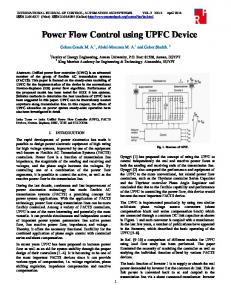
A schematic representation of the UPFC is shown in Fig. 1. It consists of two back-to-back voltage source converters, sharing a shunt capacitor on the DC side. One converter is coupled to the AC system via a series transformer while the other is coupled to the AC system via a shunt transformer. The series converter, which can inject both active power and reactive power into the series branch, is used to control series branch power flow. The real power demanded by the series converter is supplied from the AC power system by the shunt converter via the common DC link. The shunt
27 0-7803-7031-7/01/$10.00 (C) 2001 IEEE
where lt is the current variable which represents the active
converter can generate or absorb controllable reactive power. Thecontrolled shunt reactive compensation can be used to maintain the shunt converter terminal AC voltage magnitude at a specified value.
power transfer between the series converter and the shunt converter via the DC link, and 1= is the current variable which represents the active power loss of the shunt coupling transformer. Similarly, the reactive power IQ is the sum of two variables lQ = Iq+ 1X
1;
II
L. .——.
—–.u_L.
.—L—J
—.
Fig. 1 The Schematic Representation
where lq
is the reactive current component
the
converter,
shunt
of UPFC
Ix
current source Ivr. The series source impedance consists of
resistance
sequence
leakage
Ix
is the reactive
Iq
The equivalent circuit model used to derive our steadystate UPFC model is shown in Fig. 2. This new model consists of one ideal voltage source Vcr and one ideal
the positive
and
supplied by current
component represented the reactive power loss of the shunt coupling transformer. As shown in Section III, these four current source representations provides a simple way to understand power transfers among different components of UPFCS. The phasor diagram for describing various components of Ivr is shown in Fig 3.
,
–
(4)
inductance XC, , and the
Vs
It
1,
Both
Rcr of the series coupling transformer.
IL_ Iv.
Fig. 3 Phasor Diagram for describing various components of Zvr
active and reactive power loss of the shunt coupling transformer can be calculated from the shunt current lV,.
We use the scalar notation to simpli~ the phasor representation of the shunt current source lvr. For active S*.
R.,+jX., .. ..+-----.
1.,
4
.-F.
Iw
:,,:,,.3
._ /
Sending + End
,/,, “u
I b=rq+rx
Receiving End
if I and V~are outphase Similarly,
Iq, Ix and Iq, we define
.1-
Re(%~c; (1)
Vcr = lVcrl(cos~,, + jsin8Cr) where lVcrI and Ocr are the magnitude
and angle of the
the UPFC series branch can be written as:
@c, S 2Z, respectively.
(6)
According to their contributions to active power and reactive power, the ideal shunt current source Ivr can be
Thus, the active power loss of the series coupling transformer and the shunt coupling transformer can be expressed as follows:
decomposed as follows: (2)
Iv, = 1P + IQ IQ
represent
(5)
) = lK\I~
Suppose that the receiving end is set to a fixed equivalent load demand P,,, + jQr. = –Prqf – jQr.f , thecurrentof
voltage source. These variables are controlled within limits
and
components
If the UPFC converter is lossless, the active power supplied by the series converter is equal to the shunt converter active power demanded, We have
The ideal series voltage source can be expressed as:
Ip
current
if 1 lags V~by 90° .
L—.
Vcm,n -< ]% I s J’.m.. and os
power
if 1 leads V5by 90°
Fig.2 Equivalent Circuit Model of the Hybrid UPFC Model.
where
for
reactive
1
K
11,=1,:1,
II
.-1
if I and V~are inphase
I
“-
Re( V~Jc~ ‘)=/ V:/IJ
[ v,
power current components 1P, It and 1=, we define
-s’s
the active part and the
reactive part of lVr , respectively. has two components: 1P = 1++1=
0-7803-7173-9/01/$10.00 © 2001 IEEE
The active power 1P
Plosscy = Rc,11cp12 = Rc,(fij Plossvr
=
1, Iq
+
Q;.f )/lK\2
(7) (8)
The complex power transfer from the sending bus can be expressed as
(3)
28 0-7803-7031-7/01/$10.00 (C) 2001 IEEE
S~r = I’y, + jQ,,r — –
a load demand ~.r +jQ,r
–jlol~l+ZZIKI + Z(IKI + KG
(9)
Under the lossless assumption (5), the equivalent active power load demand of the sending bus is