8th Mediterranean Conference on Power Generation, Transmission, Distribution and Energy Conversion MEDPOWER 2012
Control Active and Reactive Power Flow with UPFC connected in Transmission Line Vjollca Komoni, Isuf Krasniqi, Gazmend Kabashi dhe Avni Alidemaj
Abstract— Flexible alternating current transmission systems (FACTS) technology opens up new opportunities for controlling power flow and enhancing the usable capacity of present, as well as new lines. The Unified Power Flow Controller (UPFC) is a most complex power electronic device, which can simultaneously control a local bus voltage and optimization power flows in electrical power transmission system. This paper presents active and reactive power flow control through a 400 kV transmission line by connecting the UPFC at the sending and receiving end. The objectives are to determine control and performance of UPFC, which is necessary for installation of that transmission line to control active and reactive power flow. When no UPFC is installed, active and reactive power through the transmission line cannot be controlled. Simulations are carried out in Matlab/Simulink environment to evaluate the performance of the UPFC. Index Terms— Flexible AC Transmission Systems (FACTS), Matlab/Simulink, Active and Reactive Power, transmission line, Unified Power Flow Controller (UPFC).
I. INTRODUCTION
I
n interconnected power systems, which today are very complex, there is a great need to improve utilization, while still maintaining reliability and security. While some transmission lines are charged up to the limit load, others may be overloaded, which has an effect on the values of voltage and reduces system stability and security. For this reason, it is very important to control the power flows along transmission lines to meet transfer of power needs. In the late 1980s, the Electric Power Research Institute (EPRI), introduced a new approach to solve the problem of designing and operating power systems; the proposed concept is known as Flexible AC Transmission Systems (FACTS) [10]. The main objectives of FACTS are to enhance the power transfer the capability, facilitate the power flow control and improve the security and stability of the power system. Power flow between to buses of the lossless transmission line is given by:
V. Komoni is with the Faculty of Electrical and Computer Engineering, University of Prishtina, Kosovo (
[email protected]). I. Krasniqi is with the Faculty of Electrical and Computer Engineering, University of Prishtina, Kosovo (
[email protected]). G. Kabashi is with the Transmission System and Market Operator of Kosovo, (
[email protected]). A. Alidemaj is with Energetic Corporation of Kosovo, (
[email protected]).
Pij =
Vi V j X ij
sin δ ij
Where, Vi and
δ i are
angle, V j and
δ j are
(1) the i th bus voltage magnitude and the j
th
bus voltage magnitude and
angle, X ij is the line reactance. Thus from equation (1) power in the transmission line is a function of transmission line impedance, the magnitude of sending end and receiving end voltage and the phase angle between voltages. Control the active and reactive power flow in the transmission line is possible by controlling one or a combination of the power flow arrangements. The bus voltage, line impedance and phase angle in the power system can be regulated rapidly and flexibly with FACTS technology, such as Static Var Compensator (SVC), Static Synchronous Compensator (STATCOM), Static Synchronous Series Compensator (SSSC) and Unified Power Flow Controller (UPFC), etc. The Unified Power Flow Controller (UPFC) is a second generation FACTS device, which enables independent control of active and reactive power in addition to improving reliability and quality of the supply. It is currently the most sophisticated power flow controller, as well as probably the most expensive too. The UPFC is able to control, simultaneously or selectively, all the parameters affecting power flow in the transmission line (voltage, impedance, and phase angle) [1]. The UPFC, consisting of a series and a shunt converter connected by a common dc link capacitor, can simultaneously perform the function of transmission line active/reactive power flow control in addition to UPFC bus voltage/shunt reactive power control [2], [3]. The UPFC was designed for the real-time control and dynamic compensation of ac transmission systems, providing multifunctional flexibility required to solve many of the problems facing the power industry [11]. Under the traditional power transmission concepts, the UPFC is able to control all parameters affecting power flow in transmission line, simultaneously or selectively. Otherwise, the UPFC can independently control both the active and reactive power flow in the line, unlike all other controllers.
This paper presents a possibility to control active and reactive power flow in the interconnected transmission line between three power systems. Results of simulations with UPFC installed to the interconnection line are analyzed in order to control power flows through these lines. The model of interconnected transmission lines between Kosovo, Albanian and Montenegro are studied and then developed in Matlab/Simulink. Simulations are carried out for steady state calculation and dynamic simulation.
1
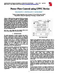
II. PRINCIPLES OF UNIFIED POWER FLOW CONTROLLER A. Operating Principles of UPFC The UPFC, which was first proposed by Gyugi in 1991 [4] consists of shunt (exciting) and series (boosting) transformers as shown in Fig. 1.
respectively. Zsh and Zse are the UPFC series and shunt coupling transformer impedances, respectively. Vi and Vj are voltages at buses i, j, respectively while Vk is the voltage of bus k of the receiving-end of the transmission line. Ish is the current through the UPFC shunt converter. The shunt converter branch active and reactive power flows, is Psh and Qsh respectively. Direction of Psh and Qsh power flow is from bus i. The currents through UPFC series converters are I ij and I ji , and the I ij = − I ji . Pij and Qij are the UPFC series active and reactive power flows, respectively, leaving bus i. Pji and Qji are the UPFC series active and reactive power flows, respectively, leaving bus j. Psh is the active power exchange of the shunt converter with the DC link. Pse is the active power exchange of the series converter with the DC link.
Fig 1. The UPFC basic circuit arrangement
The UPFC consists of two switching converters based on VSC valves. The two converters are connected by a common DC link. Both transformers are connected by two converters and a DC circuit represented by the capacitor. Converter 1 is primarily used to provide the active power demand of converter 2 at the common DC link terminal from the AC power system. Converter 1 can also generate or absorb reactive power at its AC terminal, which is independent of the active power transfer to (or from) the DC terminal. Converter 2 is used to generate a voltage source at the fundamental frequency with variable amplitude ( 0 ≤ VT ≤ VT max ) and phase angle ( 0 ≤ φ ≤ 2π ), which is added to the AC transmission line by the series connected boosting transformer. This voltage source can internally generate or absorb all the reactive power required by the different type of controls applied and transfers active power at its DC terminal. Based on basic circuit arrangement, an equivalent circuit of UPFC is established, shown in Fig.2.
B. Power Flow Constraints of UPFC For equivalent circuit of UPFC presented in Fig. 2, suppose Vsh = Vsh ∠θsh, Vse = Vse ∠θse, Vi = Vi ∠θi, Vj = Vj ∠θj; then the power flow constraints of the UPFC shunt and series branches are:
Psh = Vi2 g sh − Vi V sh ( g sh cos (θ i − θ sh ) + bsh sin (θ i − θ sh )) (2)
Q sh = − Vi2 bsh − Vi V sh ( g sh sin (θ i − θ sh ) − bsh cos (θ i − θ sh )) (3)
(
) − Vi Vse (g ij cos(θ i − θ se ) + bij sin (θ i − θ se ) ) Qij = − Vi2 bij − Vi V j (g ij sin θ ij − bij cosθ ij ) − Vi Vse (g ij sin (θ i − θ se ) − bij cos(θ i − θ se ) ) Pji = V j2 g ij − Vi V j (g ij cosθ ji + bij sin θ ji ) − V j Vse (g ij cos(θ j − θ se ) + bij sin (θ j − θ se ) ) Q ji = − V j2 bij − Vi V j (g ij sin θ ji − bij cosθ ji ) − V j Vse (g ij sin (θ j − θ se ) − bij cos(θ j − θ se ) ) Pij = Vi2 g ij − Vi V j g ij cosθ ij + bij sin θ ij
(4)
(5)
(6)
(7 )
where g sh + jbsh =1 Z sh , g ij + jbij =1 Z se , θ ij = θ i − θ j , θ ji = θ j − θ i . The active power exchange between two inverters via the DC link is: ∆PΣ = PE sh − PE se = 0 (8) Where PEsh= Re (VshI*sh) and PEse= Re (VseI*ji) are active power exchange of the shunt converter and the series converter with the DC link, respectively. C. UPFC Control Modes
Fig. 2. Equivalent circuit of UPFC
In Fig.2, the phasors Vsh and Vse represent the equivalent, injected shunt voltage and series voltage sources,
1) Shunt converter The UPFC has many possible operating modes. In particular, the shunt converter operates in such a way to inject a controllable current Ish, into the transmission line. One component of this current is determined to balance the active power of the series converter. The other components are reactive and can be set to desired reference level (inductive or capacitive) within the capability of converter. The reactive compensation control modes of the shunt converter are very similar to the STATCOM and Static Var
2
2) Series converter The series inverter controls the magnitude and angle of the voltage injected in series with the line. This voltage injection is always intended to influence the flow of power on the line. However voltage is dependent on the operating mode selected for the UPFC to control power flow. The actual value of the injected voltage can be obtained in several ways. a) Direct Voltage Injection Mode: The series converter generates a voltage vector with magnitude and phase angle requested by reference input. This operating mode may be advantaged when a separate system optimization control coordinates the operation of the UPFC and other FACTS controllers installed in the transmission system.
flow scheduling and management are reached, which would not be achievable with conventional line compensating equipment.
e) Stand alone shunt and series compensation: The UPFC circuit offers the possibility of operating shunt and series converters independently of each other by disconnecting their common dc terminals and splitting the capacitor bank. In this case, the shunt converter operates as stand alone STATCOM, and the series converter as a stand alone SSSC. This feature may be included in the UPFC structure in order to handle contingencies: if one converter failures, and is more adaptable to future system changes, the use of either converters for shunt only or series only compensation. In the stand alone mode, of course, neither converters are capable
III. CASE STADIES SYSTEM Unified Power Flow Controller (UPFC) is used to control the power flow in a 400 kV transmission line. The UPFC is simulated to be installed at the SS Kosovo B of the 239km, planned transmission line between the 400 kV buses B1 (Kosovo B) and buses B2 (Tirana 2). The simulation is used to control the active and reactive power flow through bus B2, while controlling voltage at bus B1. It consists of two 100-MVA, three-level, 48-pulse GTO-based converters, one connected in shunt at bus B1 and one connected in series between buses B1 and B2. The shunt and series converters can exchange power through a DC bus. The series converter can inject a maximum of 10% of nominal line-to-ground voltage (28.87 kV) in series with line SS Kosovo B- SS Tirana 2. The Matlab/Simulink model used to simulate the power flow control on 400kV transmission line is shown in Fig. 3. The model of interconnected transmission lines between three power systems (Kosovo, Albanian and Montenegro), with UPFC installed in bus B1 (1-KS) and bus B2 (2-AL) is shown in Fig. 4. Montenegro Power System Equivalent Load (MG)
Kosovo Power System Equivalent
~
400 kV line 90 km UPFC
Load (KS)
~
( 1-installed in Kosovo)
40 0k Vl ine 23 9
km
UP (2 FC -in s Ala talle ban d in ia)
400 kV line 180 km
b) Phase Angle Shifter Emulation mode: The reference input is phase displacement between the sending end voltage and the receiving end voltage. c) Line Impedance Emulation mode: The reference input is an impedance value to insert in series with the line impedance, in purpose to control the magnitude of voltage vector, in proportion to the size of the line current. The desired impedance is specified by reference input and in general it may be complex impedance with resistive and reactive components of either polarity. This operating mode may be selected to match existing series capacitive line compensation in the system. d) Automatic Power Flow Control Mode: The magnitude and phase angle of the injected voltage vector is controlled so as to force such a line current vector, that results in the desired active and reactive power flow in the line. In automatic power flow control mode, the series injected voltage is determined automatically and continuously by a vector control system to ensure that the desired values of P and Q to maintain on the transmission line despite system changes. With this operating mode, possibilities for power
of absorbing or generating active power, so that operation is possible only in the reactive power domain. Since the injected voltage must be in quadrature with the line current, only controlled voltage compensation or reactive impedance emulation is possible for power flow control.
~
compensation. The shunt converter can be controlled in two different modes: a) VAR Control Mode. In reactive control mode the reference input is an inductive or capacitive VAR request. In Var control mode the reference input is a simple Var request that is maintained by the control system regardless of bus voltage variation. b) Automatic Voltage Control Mode. In voltage control mode, the shunt converter reactive current is automatically regulated to maintain the transmission line voltage at the point of connection to a reference value. For this mode of control, voltage feedback signals are obtained from the sending end bus feeding the shunt transformer.
Load (AL)
Albanian Power System Equivalent
Fig. 4. System study case model to analyze impact of UPFC for two installed location 1-KS and 2-AL
Case study 1: Control of power flow for better usage of the line capacity The UPFC device is placed in series with power transmission line SS Kosovo B- SS Tirana 2 at the sending end. Initially is simulated 600MW active power flow through 400kV interconnection line SS Kosovo B – SS Tirana 2. The reference values for UPFC are set as bellow: Pref= +6 pu/100MVA (+600 MW) and Qref=-0.6pu/100MVA (-60 Mvar). We simulate increase of power flow through monitored line using UPFC control at time, t=0.4sec Pref is changed to +8 pu (+800MW). Then, at t=0.5 sec, Qref is changed to +0 pu (0 Mvar). The reference voltage of the shunt converter will
3
Fig. 3. Study system model in Matlab/Simulink with UPFC
After activation of the UPFC, active power flow in transmission line SS Kosovo B-SS Tirana 2, will increase to 800 MW, while the active power flow in transmission line SS Kosovo B- SS Podgorica will be reduced to 720 MW, and that in transmission line SS Tirana2-SS Podgorica will increase to 700 MW.
0.2 0 Q[x100MVAr]
be kept constant at Vref=1.02 pu during the whole simulation (Step Time=0.3*100>, Simulation stop time (0.8 sec). The impact of UPFC installed in the sending end of transmission line SS Kosovo B- SS Tirana 2, in active and reactive power flow, after actions the UPFC is shown in Fig. 5, and Fig. 6. Fig. 5 shows impact of the UPFC in active power flow which is transmitted through the line. UPFC is activated after 0.4 sec, and the active power has started to grow from 600 MW and after 0.2 sec it was increased to 800 MW.
-0.2 -0.4
UPCF Action for P
UPCF Action for Q
Reactive power flow of the line Reactive power reference
-0.6 8.5
-0.8 0.3
8
0.35
0.4
0.45
0.5
0.55
0.6
0.65
0.7
0.75
0.8
P[x100MW]
Time [sec'] Power flow increase of the line for 200MW
7.5 UPCF Action 7
Power flow Power flow reference
6.5
Fig. 6 Reactive power response after UPCF action installed in sending end in transmission line SS Kosova B – SS Tiraran 2.
6 5.5 0.3
0.35
0.4
0.45
0.5
0.55
0.6
0.65
0.7
0.75
0.8 Time[sec.]
850 800
MW
750
Fig. 5 Active power response after UPCF action installed in sending end in transmission line SS Kosova B – SS Tiraran 2.
700
UPCF Action
650 400kV Line SS Kosovo B - SS Podgorica 400kV Line SS Kosovo B - SS Tirana 2 400kV Line SS Tirana 2 - SS Podgorica
600
Fig. 6 shows impact of the UPFC in reactive power flow which is transmitted through the line. UPFC is activated after 0.5 sec, and the reactive power has started to grow from -60 MVAr and after 0.15 sec it was increased to 0 MVAr. While, in Fig. 7 we can observe the resulting changes in active power flow on the three transmission lines, interconnected in our study model shown in Fig. 3.
550 0.3
0.35
0.4
0.45
0.5
0.55
0.6
0.65
0.7
0.75
0.8
time[sec.]
Fig. 7 Active power response in three transmission line of study model after UPCF action
4
The same approach is used as in case 1 for analyzing the impact of UPFC when it is installed at the receiving end of the 400kV transmission line, respectively in SS Tirana 2. Initially a 500MW active power flow through 400kV interconnection line SS Kosovo B – SS Tirana 2 (from Kosovo to Albania) is simulated. The reference values for UPFC are set as bellow: Pref = +5 pu/100MVA (+500 MW) and Qref =-0.6 pu/100MVA (-60 Mvar). We simulate increase of power flow through monitored line using UPFC control at time t = 0.5sec Pref is changed to +7 pu (+700MW). Then, at t = 0.5 sec, Qref is changed to +0 pu (0 MVAr). The reference voltage of the shunt converter will be kept constant at Vref =1.01 pu during the whole simulation (Step Time=0.3*100> Simulation stop time (1.0 sec). The impact of UPFC installed in the receiving end of transmission line SS Kosovo B- SS Tirana 2, in active and reactive power flow, after actions the UPFC, is shown in Fig. 8, and Fig. 9. The simulation result shows approximately same response on active and reactive power control. Fig. 8 shows the impact of the UPFC in active power flow which is transmitted through the line. UPFC is activated after 0.5 sec, and the active power has started to grow from 500 MW and after 0.2 sec it was increased to 700 MW.
7.5
P[x 100MW]
7 6.5
200MWPower Increase
6 5.5
Active Power flow Active Power Flow Reference
5 4.5 0.4
0.5
0.6
0.7
0.8
0.9
1
Time [sec.]
Fig. 8 Active power flow response after action UPCF installed in receiving end of transmission line SS Kosova B – SS Tiraran 2.
Fig. 9 shows the impact of the UPFC in reactive power flow which is transmitted through the line. UPFC is activated after 0.5 sec, and the reactive power starts to grow from -60 MVAr and after 0.2 sec it has increased to 0 MVAr.
power flow on the three transmission lines, interconnected in our study model as shown in Fig. 3. After activation of the UPFC, active power flow in transmission line SS Kosovo B-SS Tirana 2, will increase to 700 MW, while the active power flow in transmission line SS Kosovo B- SS Podgorica will be reduced to 320 MW, and that in transmission line SS Tirana2-SS Podgorica will increase to 70 MW. 1000
600 400 200 0 0.4
0.5
10
Critical power swing
0.9
1
Active Power flow through 400kV line Tirana 2- Kosovo B Active Power Referent Signal
800MW
8 7 600MW
6
235ms time responde
0.8
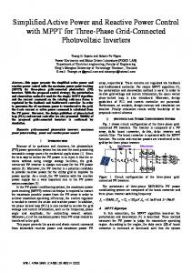
Finally we analyze the case of power swing on the system. The initial values at the sending end of the line at bus B1 we put high level of power flow from Kosovo Power System to Albania as below. The reference values for UPFC are set: Pref = +8.7 pu/100MVA (+870 MW) and Qref =-0.6 pu/100MVA (-60 Mvar). We simulate power swing on the system, which can cause relay protection to act, therefore at the time; t=0.25 sec, Pref is changed to +6 pu (+600MW) in aim to prevent line trip. Then, at t=0.5 sec, Qref is changed to +0.7 pu (+70 Mvar). The reference voltage of the shunt converter will be kept constant at Vref=1.02 pu during the whole simulation (Step Time=0.3*100> Simulation stop time (0.8 sec). The impact of UPFC installed in transmission line, is shown in Fig. 11 and Fig. 12, when are presented the variations of active and reactive power on the monitored line. As shown in Fig. 11 and Fig. 12, after a transient period lasting approximately 0.15 sec, the steady state is reached (P=+8.7 pu; Q=-0.6 pu). After UPFC reference point is changed then P and Q are ramped to the new settings (P=600MW Q=+70MVAr).
P[x100MW]
-0.2
0.7 Time[sec.]
Case study 3: Power flow reduction on the line using UPFC to avoid line overload
9
0
0.6
Fig.10 Active power response in three transmission line of study model after UPCF action
0.2
Q[x 100MVAr]
400kV Line KS - MG 400kV Line KS -AL 400kV Line AL-MG
800
P[MW]
Case study 2: Control of power flow when the UPFC is installed in SS Tirana 2.
-0.4 Reactive Power Flow Reactive Power Reference
-0.6 -0.8 0.4
5 0
0.5
0.6
0.7 Time [sec.]
0.8
0.9
1
Fig. 9 Reactive power flow response after UPCF action installed in receiving end of transmission line SS Kosova B – SS Tiraran 2.
In Fig. 10, we can observe the resulting changes in active
0.1
0.2
0.3
0.4
0.5
0.6
0.7
0.8
Fig. 11 Active power flow response after UPCF action in the power swing to prevent 400 kV interconnection line outage
While, in Fig. 13 we can observe the resulting changes in active power flow on the three transmission lines, interconnected in our study model shown in Fig. 3, in case of power swing in transmission line SS Kosovo B- SS Tirana 2. 5
1
Critical power swing
[6] B.A. Renz, A. Keri, A.S. Mehraben, C. Schauder, E. Stacey, I. Kovalsky, L. Gyugui, and A. Edris, 1999, “AEP Unified Power Flow Controller Performance”, IEEE Trans. On Power Delivery, 14(4), pp. 1374-1381.
70MVAr
Q[x100MVAr]
0.5
[7]
0 -0.5
-60MVAr
-1
[8]
Reactive power Reactive Power Reference
-1.5 0
0.1
0.2
0.3
0.4
0.5
0.6
0.7 0.8 Time[Sec.]
Fig. 12 Reactive power flow response after UPCF action in the power swing to prevent 400 kV interconnection line outage
[9]
M. Noroozian, L. Angquist, M. Ghandhari, G. Andersson, 1997, “Use of UPFC for Optimal Power Flow Control,” IEEE Transactions on Power Delivery, 12(4), pp. 1629- 1634. D. Murali, Dr. M. Rajaram, Active and Reactive Power Flow Control using FACTS Devices, International Journal Of Computer Applications (0975 – 8887), Volume 9 – No.8, November 2010. S. Tara Kalyani, G. Tulasiram Das, Simulation of Real and Reactive Power Flow Control with UPFC Connected to a Transmission Line, International Journal Of Computer Applications, 2008, (16-22)
Books: 1000 400kV Line SS Kosovo B- SS Podgorica 400kV Line SS Kosovo B- SS Tirana 2 400kV Line SS Tirana 2 SS Podgorica
800 P[MW]
UPFC Action 600 400 200 0
[10] N. G. Hingorani and L. Gyugyi, Understanding FACTS, Concepts, and Technology of Flexible AC Transmission Systems. Piscataway, NJ: IEEE Press, 2000. [11] Xiao-Ping Zhang, Christian Rehtouz, Bikash Pal, Flexible AC Transmission Systems: Modeling and Control, Springer-Verlag Berlin Heidelberg, 2006.
Papers from Conference Proceedings (Published): 0.1
0.2
0.3
0.4
0.5
0.6
0.7
0.8 Time[sec.]
Fig. 13 Active power response in three transmission line of study model after UPCF action
[12] Bhanu CHENNAPRAGADA Venkata Krishna, KOTAMARTI. S. B. Sankar, PINDIPROLU. V. Haranath, “17th International Conference on Electricity Distribution,” CIRED, Barcelona 2003, Session 5 Paper No 19.
V. BIOGRAPHIES IV. CONCLUSION This paper provide the possibility of installed the UPFC, FACTS devices on 400 kV transmission power system. Application of UPFC for control of the active and reactive power flow has been explored in this study. The Matlab/Simulink environment is used to simulate the model of interconnected transmission lines between three power systems. The control and performance of UPFC intended for installation on a transmission line is presented. Simulation results show the effectiveness of UPFC on controlling the active and reactive power flow through the transmission line with UPFC. Also showed is the impact of UPFC in power swing in preventing the line outage.
Periodicals: [1]
[2]
[3]
[4]
[5]
L. Gyugyi, C.D. Schauder, S.I. Williams, T.R. Reitman, D.R. Torgerson, and A. Edris, 1995, “The Unified Power Flow Controller: A new approach to power transmission control”, IEEE Trans. on Power Delivery, 10(2), pp. 1085-1095. M. Noroozian, L. Angquist, M. Ghandhari, G. Andersson, 1997, “Use of UPFC for Optimal Power Flow Control,” IEEE Transactions on Power Delivery, 12(4), pp. 1629-1634. B.A. Renz, A. Keri, A.S. Mehraben, C. Schauder, E. Stacey, I. Kovalsky, L. Gyugyi, and A. Edris, 1999, “AEP Unified Power Flow Controller Performance”, IEEE Trans. o Power Delivery, 14(4), pp. 1374-1381. L. Gyugi, Unified power flow controller concept for flexible AC transmission systems, IEE Proceedings-C, Vol.139, No.4, July 1992, pp. 323-331. K.S. Verma,, S.N. Singh, H.O. Gupta, Location of unified power flow controller for congestion management, Electric Power Systems Research 58 (2001) 89-96.
Vjollca Komoni obtained the Dipl. Ing. Degree from the University of Prishtina, Kosovo in 1976, the M.S. degree from the University of Zagreb, Croatia in 1982, and the Ph.D. degree from Polytechnic University of Tirana in 2008, all in electrical engineering. Currently, she works as a professor association at the Faculty of Electrical and Computer Engineering the University of Prishtina. Her research interests are in stability and control of power systems. Isuf Krasniqi obtained the Dipl.Ing degree from the University of Prishtina, Kosovo in 1972, the M.S. degree from the University of Zagreb, Croatia in 1978 and the Ph.D degree from the University of Prishtina, Kosovo, in 1987. Currently, he works as a professor at the Faculty of Electrical and Computer Engineering the University of Prishtina. He is the member of Academy of Science and Arts of Kosova. His research interests are in High voltage technique and Coordination insulations. Gazmend Kabashi received his electrical engineering ing. Degree from University of Prishtina, Kosovo in 2003. The M.S. degree received in 2008 in the same Faculty. He is a Ph.D. applicant in Power System Department at the Faculty of Electrical and Computer Engineering the University of Prishtina. Since 2003 he is with Transmission System and Market Operator of Kosovo ( KOSTT) working on long term development of transmission network. His research interests are in transient stability of power systems, and Wind Power energy. Avni Alidemaj Was graduated as electrical engineer at University of Prishtina, Kosovo in 1997.The M.S. degree in the same faculty in 2008. Currently work as Executive Director in Distribution Division in Power Corporation of Kosova (Korporata Energjetike e Kosovës-KEK). His research interests are in High voltage technique and Coordination insulations.
6