A New Hybrid UPFC Controller for Power Flow Control and Voltage
Recommend Documents
Apr 2, 2014 - Alexandria, EGYPT. Abstract:- Unified power flow controller (UPFC) is an advanced member of the group of flexible AC transmission systems.
system with an UPFC installed between buses sand r confirm the efficacy of the new approach in ..... of spinning the roulette wheel[l2]. The selections can be.
Oct 4, 2015 - malfunction in the form of over-reaching or under- reaching the fault point [3]. The control characteristics of the UPFC, the fault location with ...
Fig 2.4 Two machine system with Unified Power Flow Controller. 12. Fig 2.5 Attainable sending-end reactive power vs. tra
Index Termsâ Flexible AC Transmission Systems (FACTS),. Matlab/Simulink, Active and Reactive Power, transmission line, Unified Power Flow Controller ...
control through a 400 kV transmission line by connecting the. UPFC at the ... active and reactive power through the transmission line cannot be controlled.
Engineering, Vellore Institute of Technology, Deemed University,. Vellore 632 014, India ..... Short-listing of possible lines for installation of. UPFC. ⢠Identification ...
implementation and validation of power system on-line management. Current ... Matlab/Simulink, for modeling and simulation of power systems are ...
Abstractâ this paper presents two new methods for power flow calculation of power systems in presence of Dynamic Flow. Controller (DFC), which is a new ...
NS1 (negative small1), VS1 (very small1), PS1 (positive small1), PM1 (positive medium1), ..... 2000. [18] S. Ahmad, F. M. Albatsh, S. Mekhilef, and H. Mokhlis, ...
Keywords â FACTS, UPFC, Voltage Source Convertor, power flow controller .... and if its phase angle with respect to V1 is varied from 0 to 360 degrees, the.
software in [14]. In [15], effects of SVC and STATCOM in static voltage stability margin enhancement were studied. Simulation and comparison of various FACTS.
power transfers, series transformer and shunt transformer ... neglecting active power losses of coupling transformers [6]. ..... Here we list modified entries.
This paper targets the power flow control of multi-terminal high voltage DC networks ... Comparatively, voltage source converter (VSC) based HVDC is a new ...
Sep 23, 2012 - unit (DC-DC converters controller) of the different power sources. Dynamic ...... [17] O. Gergaud, G. Robin, B. Multon, and H. Ben Ahmed,.
response to the flexibility in the way that the transmission system is operated is found by applying the Flexible AC. Transmission Systems (FACTS) concept [1].
Electric power flow through an alternating current trans- mission line depends on the line parameters and complex voltages at the sending end and receiving ...
Abstract â A new component within the FACTS family( flexible ac-transmission system), called distributed power-flow controller. (DPFC) which is modification of ...
Abstract-Optimization of system capacity electric power transmission systems requires a reliable ..... Y. H. Song, A. T. Jons, âFlexible AC Transmission Systems.
Keywords: Emergency voltage control, power systems, model predictive control ..... piler HYSDEL (HYbrid System DEscription Language) gener- ating the ...
program to demonstrate the system behavior of the IPFC. Key words - FACTS, SSSC, IPFC, Series Compensation. I. INTRODUCTION. Flexible AC Transmission ...
The flow of electricity through the transmission lines can be effectively and
efficiently controlled by using interline power flow controllers instead of going.
AbstractâRecent development of power electronics introduces the use of flexible ac transmission systems (FACTS) controllers in power systems. These devices ...
AbstractâThis paper proposes a method to embed the AC power flow problem with voltage magnitude constraints in the complex plane. Modeling the action of ...
A New Hybrid UPFC Controller for Power Flow Control and Voltage
Sep 17, 2017 - This paper presents a new technique to design a Unified Power Flow Controller (UPFC) for power flow control and DC voltage regulation of an ...
Hindawi Advances in Electrical Engineering Volume 2017, Article ID 7873491, 11 pages https://doi.org/10.1155/2017/7873491
Research Article A New Hybrid UPFC Controller for Power Flow Control and Voltage Regulation Based on RBF Neurosliding Mode Technique Godpromesse Kenne,1 René Fochie Kuate,1,2 Andrew Muluh Fombu,1,2 Jean de Dieu Nguimfack-Ndongmo,1 and Hilaire Bertrand Fotsin2 1
1. Introduction Presently, it is well established in the scientific community that the UPFC has the ability to increase the power flow capacity and improve the stability of an electric power transmission system through the proper design of its controller [1]. Over the past several decades, linear and nonlinear control techniques have been successfully proposed and applied in the literature for the control of UPFC based on modern and classical control theories [2–10]. However, the main drawback of such techniques is that their application requires the development of mathematical models which are difficult to obtain. Thus, only partial and quite weak results have been obtained in terms of online implementation feasibility. Faced with these difficulties, intelligent controls such as fuzzy logic and artificial neural networks have emerged as better alternatives to the conventional linear and nonlinear control methods. However, the complexities associated with the adaption of membership functions and computation
requirements for defuzzification have hindered the application of fuzzy logic [11–15]. Hence, recent studies have turned to artificial neural networks (ANN) to achieve the desired goals [16–18]. Artificial neural networks have an inherent capability to learn and store information regarding the nonlinearities of the system and to provide this information whenever required. This renders the neural networks suitable for system identification and control applications [19–21]. Although intelligent and hybrid algorithms are already being implemented in the domains of image processing, robotics, financial management, and so on, their application in the field of FACTS devices for power flow control is fairly recent. Some recent results can be found in [12, 16, 17, 22, 23]. In [16], a radial basis function neural network has been designed to control the operation of the UPFC in order to improve its dynamic performance. Simulation and experimental results were presented to demonstrate the robustness of the proposed controller against changes in
2
Advances in Electrical Engineering Series transformer − V se +
Vs
Ssh = Psh + jQsh + V sh
Vsep
Vsp Vr
+ R
L
Vrp Isep
Ishp
Sse = Pse + jQse
L sh
DC-link + Shunt Series C converter converter V dc
Rsh + Vshp
Shunt transformer (a)
(b)
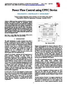
Figure 1: UPFC in power system. (a) Schematic diagram of the UPFC system. (b) Single-phase representation of the UPFC system.
the transmission system operating conditions. However, large memory and long computation time are required for its proper functioning and, in addition, the controller is designed under the assumption that the upper bound of the disturbance is known. A comparative study of transient stability and reactive power compensation issues in an autonomous wind-diesel-photovoltaic based hybrid system using robust fuzzy-sliding mode based Unified Power Flow Controller has been presented in [12], but it has the limitation that a linearized small-signal model of the hybrid system is considered for the transient stability analysis. Hence, the system will suffer from performance degeneracy when the operating condition changes. In [22], the recently proposed 𝐻∞ -learning method for updating the parameter of a single neuron radial basis function neural network has been used as a control scheme for the UPFC to improve the transient stability performance of a multimachine power system. However, the updating control parameters are optimized for each perturbation using a generic algorithm which increases the computational burden and makes the control implementation less feasible. A neural network predictive controller for the UPFC has been designed in [23] to improve the transient stability performance of the power system. Nevertheless, the neural network controller is implemented only on the series branch of the UPFC which limits the performance of the device. In [17], a neural network controller based on a feedback linearization autoregression average model is used to design an adaptive-supplementary unified power flow control for two interconnected areas of a power system. However, in this paper and many others, the bounds of system uncertainty and disturbances are assumed to be known. But in practice, it is always difficult to determine the exact upper limit of system uncertainty and disturbances. Hence, the above controllers cannot provide satisfactory results. From the above drawbacks, in this paper, a new hybrid approach which combines RBF neural network with the sliding mode technique to design a UPFC controller for power flow control and DC voltage regulation of an electric power transmission system with unknown bounds of system uncertainty and disturbances is proposed. The advantages of this design philosophy are that the controller is suitable for practical implementation and it makes the design useful for the real world complex power system. The remaining sections of this paper are organized as follows. In Section 2,
the mathematical model of a UPFC in 𝑑𝑞 reference frame is described. The design of the RBF neurosliding mode controller is developed in Section 3. In Section 4, simulation results in a Kundur two-area four-machine power system are presented. Finally, in Section 5, some concluding remarks end the paper.
2. System Modeling Figure 1(a) shows a schematic diagram of a UPFC system, while Figure 1(b) shows a single-phase representation of the power circuit of the UPFC which consists of two back-toback self-commutated voltage source converters connected through a common DC-link [24, 25]. The series converter is coupled to the AC system through a series transformer and the shunt converter is coupled through a shunt transformer. In Figure 1(b), the series and shunt converters are represented by the voltage sources Vse and Vsh , respectively. The subscripts “𝑠,” “𝑟,” and “𝑝” are used to represent the sending-end bus, receiving end bus, and the three-phase quantities (phases 𝑎, 𝑏, 𝑐), respectively. Also 𝑅 and 𝐿 represent the resistance and leakage inductance of series converter, respectively, 𝑖se is the line current, 𝑅sh , 𝐿 sh , and 𝑖sh are the resistance, inductance, and current of the shunt converter, respectively. The series and shunt branch currents of the circuit in Figure 1(b) can be expressed by the following three-phase system of differential equations [24–26]: 𝑑𝑖se𝑝 𝑑𝑡
=
1 (−𝑅𝑖se𝑝 + Vse𝑝 + V𝑠𝑝 − V𝑟𝑝 ) , 𝐿
(1) 1 = (−𝑅𝑖sh𝑝 + Vsh𝑝 − V𝑠𝑝 ) . 𝑑𝑡 𝐿 Using Park’s transformation and assuming that the instantaneous power is kept invariant and the sending-end voltage vector V𝑠 is in the 𝑑-axis (i.e., V𝑠 = (V𝑠𝑑 + 𝑗V𝑠𝑞 ) = (V𝑠𝑑 + 𝑗0)), the three-phase system of differential equations (1) can be transformed into an equivalent two-phase (𝑑, 𝑞) system of equations as follows: 𝑑𝑖sh𝑝
Advances in Electrical Engineering 𝑑𝑖sh𝑑 𝑅 1 (V − V𝑠𝑑 ) , = − sh 𝑖sh𝑑 + 𝑤𝑖sh𝑞 + 𝑑𝑡 𝐿 sh 𝐿 sh sh𝑑 𝑑𝑖sh𝑞 𝑑𝑡
= −𝑤𝑖sh𝑑 −
𝑅sh 1 (V ) , 𝑖 + 𝐿 sh se𝑞 𝐿 sh sh𝑞
3 (4) (5)
where 𝑤𝑏 = 2𝜋𝑓𝑏 is the fundamental angular frequency of the supply voltage and 𝑤 = 2𝜋𝑓 is the angular frequency of synchronous reference frame (rad/s). Since the series and shunt converters of the UPFC are coupled through a common DC-link, if the losses in the converters are neglected, then the dynamic of the DC-link voltage can be expressed as [27] 𝑑Vdc 1 (𝑃 + 𝑃sh ) , =− 𝑑𝑡 Vdc 𝐶dc se
(6)
where 𝑃se and 𝑃sh are the active power supplied by the series and shunt converters, respectively, and Vdc is the voltage of the DC capacitor of capacitance 𝐶dc . It is clear from (6) that Vdc decreases when 𝑃se + 𝑃sh > 0 and it increases when 𝑃se + 𝑃sh < 0. Note that (6) is a nonlinear differential equation and has to be investigated at 2 an operating point. However, the derivative of Vdc can be written as 2 𝑑Vdc 𝑑V = 2Vdc dc . 𝑑𝑡 𝑑𝑡
(7)
2 can be expressed as Using (6) and (7), the derivative of Vdc 2 𝑑Vdc 2 = − (𝑃se + 𝑃sh ) . 𝑑𝑡 𝐶
(8)
Maintaining constant DC-link voltage is very important for the UPFC control system [1, 28, 29]. The DC-link voltage varies when 𝑃se + 𝑃sh ≠ 0. Since (8) does not contain a direct control signal like (4), we will consider 𝑃sh as an auxiliary input that can be used to maintain the DC-link voltage constant.
𝑆𝑥 = 𝑒𝑥 + 𝐶𝑥 ∫ 𝑒𝑥 𝑑𝑡,
(10)
where 𝐶𝑥 > 0 is a design parameter. The integral term is included in the sliding manifold 𝑆𝑥 so as to ensure that the system trajectories start on the sliding manifold from the first instant of time. From (10), we have 𝑆𝑥̇ = 𝑒𝑥̇ + 𝐶𝑥 𝑒𝑥 = 𝑥̇ + 𝐶𝑥 𝑒𝑥 − 𝑥̇∗ = 𝑓 (𝑥, 𝑡) + 𝑔 (𝑥, 𝑡) 𝑢 + 𝜇𝑥 + 𝑑 (𝑡) ,
(11)
with 𝜇𝑥 = 𝐶𝑥 𝑒𝑥 − 𝑥̇∗ . From 𝑆𝑥̇ , if the desired sliding mode controller is chosen as [31] 𝑢𝑥∗ = −
𝑆 1 (𝑓 (𝑥, 𝑡) + 𝜇𝑥 + 𝑑 (𝑡)) − 𝑥 , 𝑔 (𝑥, 𝑡) 𝜖𝑥
(12)
where 0 < 𝜖𝑥 < 1 is a design parameter, then 𝑆𝑥̇ = 𝑆𝑥 /𝜖𝑥 and 𝑆𝑥 will converge exponentially to 0. The above desired controller (12) is not implementable in practice since the functions 𝑓(𝑥, 𝑡) and 𝑔(𝑥, 𝑡) and the terms 𝜇𝑥 and 𝑑(𝑡) are assumed to be unknown. Hence, in this work, a RBF neural network combined with the sliding mode technique will be applied to approximate the unknown controller 𝑢𝑥∗ . The control signal (12) can be approximated by the neural controller proposed in [31] as 𝑢𝑥∗ (𝜒𝑥 , 𝑡) = Ψ (𝜒𝑥 , 𝑤∗ ) + 𝑒𝑓 (𝜒𝑥 ) + 𝛿𝑢𝑥 (𝑡) ,
𝑗=1
In this section, the method proposed in [30, 31] for timevarying parameter estimation will be modified and applied to design a robust adaptive controller for the UPFC using the RBF neural network. Let us consider the SISO first-order nonlinear system in the following form:
concentrated in the term 𝑑(𝑡) assumed to be bounded by an unknown constant 𝑑0 > 0. Since all physical plants operate in bounded regions, we study the control problem of system (9) whose state 𝑥 belongs to a compact subset Ω ⊂ 𝑅. Let the desired smooth signal 𝑦∗ = 𝑥∗ , the tracking error 𝑒𝑥 , and augmented item 𝑆𝑥 be defined as
(9)
where 𝑥 ∈ 𝑅, 𝑢 ∈ 𝑅, and 𝑦 ∈ 𝑅 are state variables, system input, and system output, respectively; 𝑓(𝑥, 𝑡) and 𝑔(𝑥, 𝑡) are unknown smooth functions; 𝑓(𝑥, 𝑡) represents the nominal part of the system which does not depend upon the control input, while the uncertainties and external disturbance are
where 𝜙(⋅) denotes a nonlinear function; 𝐶𝑗 and ]𝑗 , 𝑗 = 1, . . . , 𝑁, are the center and the width of the 𝑗th hidden unit, respectively; 𝑁 is the number of hidden nodes or Radial Basis Function (RBF) units; 𝑤∗ is the optimal weight vector and satisfies ‖𝑤∗ ‖ ≤ 𝑅𝜔 ; 𝜒𝑥𝑇 = (𝑥, 𝑆𝑥 , 𝑆𝑥 /𝜖𝑥 ) is the input vector of the RBF network; 𝑒𝑓 (𝜒𝑥 ) is the optimal approximation error, which is unknown and bounded ∀𝜒𝑥 ∈ Ω𝑥 . 𝐶𝑗 and ]𝑗 , 𝑗 = 1, . . . , 𝑁, are chosen, respectively, using the Clustering algorithm [32] as follows: ]𝑗 =
d_theta (deg) w w (pu) Pa Pa (pu) Vt Vt (pu) Stop Machines
Machine signals Scope
Stop
Stop simulation if there is loss of synchronism
Figure 2: Kundur power system test.
where 𝜒𝑥min and 𝜒𝑥max are the lower and upper bounds of the 𝑖th element of the RBF input vector 𝜒𝑥𝑇 = (𝑥, 𝑆𝑥 , 𝑆𝑥 /𝜖𝑥 ), respectively. Note that the term 𝛿𝑢𝑥 (𝑡) is time-varying and cannot be approximated by a static neural network. In the following analysis, sliding robust terms will be used in the identification scheme to compensate the effect of this uncertainty timevarying term. The controller 𝑢𝑥∗ (𝜒𝑥 , 𝑡) will be approximated assuming that the terms 𝑒𝑓 (𝜒𝑥 ) and 𝛿𝑢𝑥 (𝑡) are bounded by unknown positive constants. For this purpose, the following neural controller is proposed in order to approximate the control signal 𝑢𝑥∗ (𝜒𝑥 , 𝑡) ̂) + 𝑏𝑥 (𝑡) , 𝑢̂𝑥∗ (𝜒𝑥 , 𝑡) = Ψ (𝜒𝑥 , 𝑤
(15)
where the term 𝑏𝑥 (𝑡) is introduced in order to improve the convergence rate of the neural network in the presence of the uncertainties terms. Consider the systems described by (9), the sliding-neural network controller (15), and Assumptions 1 and 2 given in [31]. If the bias term 𝑏𝑥 (𝑡), the learning rule of the weight 𝑤, and the adaptation law for the unknown bound 𝜆 𝑥 are chosen as ̂ sgn (𝑆 ) , 𝑏𝑥 (𝑡) = −𝜆 𝑥 𝑥
𝜕Ψ ̇ [ ], ̂𝑗 = Proj −𝑆𝑥 𝑤 𝜕𝑤𝑗 𝑤 =̂ 𝑗 𝑤𝑗 ] [ 𝜕Ψ { { ̂𝑗 < 𝑅𝑤 , , if 𝑤 { −𝑆𝑥 𝜕𝑤𝑗 𝑤 =̂ ={ 𝑤 𝑗 𝑗 { { otherwise, {0, 𝑗 = 1, . . . , 𝑁 {𝛼𝑥 , if 𝑆𝑥 ≠ 0, ̂̇ = 𝜆 𝑥 { 0, if 𝑆𝑥 = 0, { (16) ̂ (0) = 0, and Proj(⋅) the well-known projection with 𝛼𝑥 > 0, 𝜆 𝑥 function [33] on the compact set Ω𝜔 = {𝜔 : ‖𝜔‖ ≤ 𝑅𝜔 }, then the neural network controller error 𝑆𝑥 will converge in finite time to the origin. The proof of the convergence of above neural network controller to zero can be found in [31]. In order to apply the neurosliding controller described above to power flow control, UPFC sending-end bus voltage control and DC-link voltage control, the dynamic equations of the UPFC completely described by (2) to (5) and (8) can be rewritten as
Advances in Electrical Engineering
5
Id_SH (pu)
PB3 (pu)
(i) 2.2 2
0.2 0.15 0.1
1.8 0
0.1
0.2
0.3
0.4
0.5
(i)
0.25
0
0.6
0.1
0.2
0.2
0.3
0.4
0.5
0.6
QB3 (pu)
Iq_SH (pu)
0.1
0.4 0.2 0 −0.2 −0.4
0
0.1
0.6
0.3
0.4
0.5
0.6
0.3
0.4
0.5
0.6
0.3 Time (s)
0.4
0.5
0.6
(iii) Id_SE (pu)
2.2
0
0.1
0.2
0.3
0.4
0.5
2 1.8 1.6
0.6
0
0.1
0.2 (vi)
(iv)
1.01
Iq_SE (pu)
VB2 (pu) VDC (pu)
0.5
0.2
(iii) 1.01 1 0.99 0.98 0.97
0.4
(iii)
(ii) 0.8 0.6 0.4 0.2 0 0
0.3
1 0.99 0
0.1
0.2
0.3 Time (s)
0.4
0.5
0.6
REF PI NSC
0.6 0.4 0.2 0 −0.2
0
0.1
0.2
SNC PI (b)
(a)
Figure 3: Control response to step changes in real and reactive power flow references in the transmission line. (a) (i) Active power at bus B3. (ii) Reactive power at bus B3. (iii) Voltage magnitude at bus B2. (iv) UPFC DC-link voltage. (b) (i) 𝐷-axis current of shunt converter. (ii) 𝑄-axis current of shunt converter. (iii) 𝐷-axis current of series converter. (iv) 𝑄-axis current of series converter.
Figure 4: Control response to step changes in real and reactive power flow references in the transmission line. (a) (i) 𝐷-axis voltage of shunt converter. (ii) 𝑄-axis voltage of shunt converter. (iii) 𝐷-axis voltage of series converter. (iv) 𝑄-axis voltage of series converter. (b) (i) Active power at bus B2. (ii) Active power at bus B5. (iii) Reactive power at bus B2. (iv) Reactive power at bus B5.
2 𝑥5 = Vdc ;
∗ = (𝑘𝑝𝑎𝑐 + 𝑥4∗ = 𝑖sh𝑞
2 𝑓5 (𝑥, 𝑡) = − 𝑃se ; 𝐶
2∗ , 𝑥5∗ = Vdc
(19)
2 𝑔5 (𝑥, 𝑡) = − ; 𝐶 𝑢5 = 𝑃sh , (18) where 𝑑1 (𝑡) to 𝑑5 (𝑡) represent system uncertainties. The reference values of the state variables are obtained as ∗ 𝑥1∗ = 𝑖se𝑑 =
∗ 𝑥2∗ = 𝑖se𝑞 =
𝑥3∗
=
∗ 𝑖sh𝑑
∗ ∗ 2 𝑃𝑟 V𝑟𝑑 + 𝑄𝑟 V𝑟𝑞
,
3
2 + V2 V𝑟𝑑 𝑟𝑞
2 3
𝑃𝑟∗ V𝑟𝑞 − 𝑄𝑟∗ V𝑟𝑑 , 2 + V2 V𝑟𝑑 𝑟𝑞 ∗
𝑘𝑖𝑎𝑐 ) (Vref − V𝑠𝑑 ) , 𝑠
∗
2 𝑃sh V𝑠𝑑 + 𝑄sh V𝑠𝑞 = , 2 + V2 3 V𝑠𝑑 𝑠𝑞
where 𝑃𝑟∗ and 𝑄𝑟∗ are the active and reactive power references at the receiving end bus of the transmission line, respectively. We can design the neurosliding controller 𝑢̂𝑘∗ using the UPFC dynamics given in (17) as (for 𝑘 = 1, . . . , 5) ̂𝑘 ) + 𝑏𝑥𝑘 (𝑡) , 𝑢̂𝑘∗ (𝜒𝑥𝑘 , 𝑡) = Ψ (𝜒𝑥𝑘 , 𝑤 𝑇 𝜒𝑥𝑘 = (𝑥𝑘 , 𝑆𝑥𝑘 ,
Figure 5: Control response to load variation. (a) (i) Active power at bus B3. (ii) Reactive power at bus B3. (iii) Voltage magnitude at bus B2. (iv) UPFC DC-link voltage. (b) (i) Active power at bus B2. (ii) Active power at bus B5. (iii) Reactive power at bus B2. (iv) Reactive power at bus B5.
4. Simulation Results The performance of the proposed nonlinear controller is evaluated through digital simulations using MATLAB/ SIMULINK software. The power system used is a Kundur two-area four-machine power system shown in Figure 2. The details of system data and initial operating point are given in [34]. The proposed controller can be applied to a UPFC connected between any two buses of the power system (with 𝑛 bus) regardless of the interaction between these two buses and other buses. Only local measurements information is
required for the implementation of the proposed algorithm. The simulation results of the proposed controller (SNC) are compared with conventional Proportional Integral (PI) controllers used for power flow control, UPFC sending-end bus voltage control, and DC-link voltage control. These classical controllers are tuned using optimal control techniques and the parameters obtained are given in the Appendix. To evaluate the performance of the proposed controller, four sets of simulations have been performed. In all simulations, the uncertainty factor is set at +10%. That is the parameters of the system under simulation are set at 110% compared to the same parameters introduced in the controller. 4.1. Step Changes in Transmission Line Real and Reactive Power Flow References. In this case study, the initial complex power flow (𝑃B3 + 𝑗𝑄B3 ) at the receiving end of the transmission line is found as (1.8 + 𝑗0.0) pu. A step change in active power reference from 1.8 to 2.2 pu and reactive power reference from 0.0 to 0.5 pu of the transmission line take place at 𝑡 = 0.02 s and 0.32 s, respectively. The simulation results for this case study are depicted in Figures 3 and 4. It can be seen from these figures that the active and reactive power flow through the transmission line, the UPFC DC-link voltage,
8
Advances in Electrical Engineering
Vd_SH (pu)
PB3 (pu)
(i) 2.2 2 1.8
0
0.05
0.1
0.15
0.2
0.25
0.3
(i)
1.5 1 0.5
0
0.05
0.1
0.15
0.6 0.4 0.2 0 0.05
0.1
0.15 (iii)
0.2
0.25
−0.1
0
0.05
0.1
0.15 (iv)
0.2
0.15 Time (s)
0.2
1.1
0.25
0.3 Vq_SE (pu)
VDC (pu)
−0.05
0.3
1 0.95
1 0.9 0
0.05
0.1
0.3
0
Vd_SE (pu)
VB2 (pu)
0
0.25
(ii) Vq_SH (pu)
QB3 (pu)
(ii)
0.2
0.25
0.3
0
0.05
0.1
0.15 (iii)
0.2
0.25
0.3
0
0.05
0.1
0.15
0.2
0.25
0.3
0.2
0.25
0.3
0.1 0
(iv)
0.25
0.2
0
0.05
0.1
0.15 Time (s)
REF SNC (a)
(b)
Figure 6: Control response to measurement noise. (a) (i) Active power at bus B3. (ii) Reactive power at bus B3. (iii) Voltage magnitude at bus B2. (iv) UPFC DC-link voltage. (a) (i) 𝐷-axis voltage of shunt converter. (ii) 𝑄-axis voltage of shunt converter. (iii) 𝐷-axis voltage of series converter. (iv) 𝑄-axis voltage of series converter.
and the voltage magnitude at bus B2 are controlled effectively. The results also clearly show that the response speed and transient conditions are further improved with the proposed controller as compared to the conventional PI controllers. Figure 4 clearly shows the excellent performance of the UPFC in power flow control under the influence of the proposed controller. 4.2. Load Variation. In practice, the references values of the control power system remain constant and the quantities being controlled vary under the effect of load variation, disturbance, and other perturbations. In this case study, the load increases by 20% of its nominal value from 𝑡 = 0.02 s. The simulation results are depicted in Figure 5. It can be noticed in these figures that the active and reactive power flow through the transmission line, the DClink voltage, and the voltage magnitude at bus B2 are all regulated to their respective reference values. Figure 5 shows that the excess active and reactive power requested by the load is supplied only by generator G2. The figure also demonstrates once more the excellent performance of the proposed controller in terms of overshot and settling time. 4.3. Robustness to Measurement Noise. In practice, it is not possible to measure a signal accurately due to the presence
of noise. For this reason, the third case study investigates the robustness of the proposed nonlinear controller with respect to measurement noise (uncertainties). In this case study, all simulations are conducted under noise conditions in the measured line currents with the magnitude of the noise reaching about 4% of the maximum value of the measurable line currents. A step change in reactive power under the same conditions as in the first case study is used to evaluate the robustness of the system. The simulation results for this case study are depicted in Figure 6. From these results, it can be seen that the active and reactive power flow through the transmission line, the UPFC DC-link voltage, and the voltage magnitude at bus B2 are all regulated to their respective reference values despite the presence of measurement noise. Hence, it can be concluded that the controller exhibits an excellent noise resistance. 4.4. Three-Phase-to-Ground Fault Test. In this case study, a three-phase-to-ground fault is applied on bus-5 and the fault is cleared after 100 ms. Simulation results for this case study are shown in Figure 7. From these results, it can be seen that the proposed controller rapidly steers the system to its prefault steady state and satisfactorily improves the transient stability of the power system as compared to the conventional PI controllers.
Figure 7: Control response to three-phase fault. (a) All generator rotor angle in COI. (b) All terminal generator voltage.
5. Conclusion In this paper, a new hybrid approach which combines Radial Basis Function (RBF) neural network with the sliding mode technique has been used to design a Unified Power Flow Controller (UPFC) for power flow control, UPFC sendingend voltage control, and DC voltage regulation of an electric power transmission system. The RBF neurosliding mode control technique uses online training to get its optimal parameter values. The proposed technique is robust and does not need the knowledge of the perturbation bounds nor the full state of the nonlinear system. The performance of the proposed controller has been evaluated through simulations on a Kundur power system and compared with a classical PI controller. Simulation results have shown the effectiveness and satisfactory performance of the proposed controller in dealing with the perturbations considered. Future works should be targeted towards the extension of the proposed
hybrid approach to a wide area interconnected power system for power oscillation damping.
Appendix Simulation Parameters (i) The parameters of the UPFC are shown in Table 1. (ii) PI controllers parameters are as follows: Series converter: 𝐾𝑝 = 0.16; 𝐾𝑖 = 8.33. Shunt converter: 𝐾𝑝 = 0.2; 𝐾𝑖 = 20. DC-link: 𝐾𝑝 = 10−3 ; 𝐾𝑖 = 15 ∗ 10−3 . (iii) RBF controller parameters are as follows: 𝐶𝑥1 = 0.15;
10
Advances in Electrical Engineering 𝐶𝑥2 = 0.05;
[11] L. Saribulut, A. Teke, and M. T¨umay, “Dynamic control of unified power flow controller under unbalanced network conditions,” Simulation Modelling Practice and Theory, vol. 19, no. 2, pp. 817–836, 2011.
𝐶𝑥3 = 10−3 ; 𝐶𝑥4 = 3 ∗ 10−3 ;
[12] A. Mohanty, S. Patra, and P. K. Ray, “Robust fuzzy-sliding mode based UPFC controller for transient stability analysis in autonomous wind-diesel-PV hybrid system,” IET Generation, Transmission & Distribution, vol. 10, no. 5, pp. 1248–1257, 2016.
𝐶𝑥5 = 3 ∗ 10−4 ; 𝑁 = 5. (A.1) ̂𝑗 are randomly initialized. The values of 𝑤
Conflicts of Interest The authors declare that they have no conflicts of interest.
References [1] I. Papic, P. Zunko, D. Povh, and M. Weinhold, “Basic control of unified power flow controller,” IEEE Transactions on Power Systems, vol. 12, no. 4, pp. 1734–1739, 1997. [2] S. Kannan, S. Jayaram, and M. M. A. Salama, “Real and reactive power coordination for a unified power flow controller,” IEEE Transactions on Power Systems, vol. 19, no. 3, pp. 1454–1461, 2004. [3] B. Lu and B.-T. Ooi, “Nonlinear control of voltage-source converter systems,” IEEE Transactions on Power Electronics, vol. 22, no. 4, pp. 1186–1195, 2007. [4] A. Zangeneh, A. Kazemi, M. Hajatipour, and S. Jadid, “A Lyapunov theory based UPFC controller for power flow control,” International Journal of Electrical Power & Energy Systems, vol. 31, no. 7-8, pp. 302–308, 2009. [5] B. Lei and S. Fei, “A brand new nonlinear robust control design of SSSC for transient stability and damping improvement of multi-machine power systems via pseudo-generalized Hamiltonian theory,” Control Engineering Practice, vol. 29, pp. 147–157, 2014. [6] J. D. D. Nguimfack-Ndongmo, G. Kenn´e, R. Kuate-Fochie, A. Cheukem, H. B. Fotsin, and F. Lamnabhi-Lagarrigue, “A simplified nonlinear controller for transient stability enhancement of multimachine power systems using SSSC device,” International Journal of Electrical Power & Energy Systems, vol. 54, pp. 650– 657, 2014. [7] A. Ajami, S. H. Hosseini, S. Khanmohammadi, and G. B. Gharehpetian, “Modeling and control of C-UPFC for power system transient studies,” Simulation Modelling Practice and Theory, vol. 14, no. 5, pp. 564–576, 2006. [8] A. Hamache, M. O. Bensidhoum, and H. Chekireb, “RoRobust sliding mode control of unified power flow controllerfor power flow tracking,” in Proceedings of the 8th International Conference on Modelling, Identification and Control (ICMIC ’16), pp. 412– 417, Algiers, Algeria, November 2016. [9] A. Khodabakhshian, M. R. Esmaili, and M. Bornapour, “Optimal coordinated design of UPFC and PSS for improving power system performance by using multi-objective water cycle algorithm,” International Journal of Electrical Power & Energy Systems, vol. 83, pp. 124–133, 2016. [10] S. K. Routray, R. K. Patnaik, and P. K. Dash, “Adaptive nonlinear control of UPFC for stability enhancement in a multimachine power system operating with a DFIG based wind farm,” Asian Journal of Control, vol. 19, no. 5, pp. 1–20, 2017.
[13] M. Fadi, A. Shameem, M. Saad, A. Ibrahim, and A. H. Mohd Fairuz, “Power flow control using fuzzy based UPFC under different operating conditions,” Journal of Electrical Systems, vol. 13, no. 2, pp. 398–414, 2017. [14] F. M. Albatsh, S. Mekhilef, S. Ahmad, and H. Mokhlis, “Fuzzy logic based UPFC and laboratory prototype validation for dynamic power flow control in transmission lines,” IEEE Transactions on Industrial Electronics, 2017. [15] M. Khaksar, A. Rezvani, and M. H. Moradi, “Simulation of novel hybrid method to improve dynamic responses with PSS and UPFC by fuzzy logic controller,” Neural Computing and Applications, 2016. [16] M. E. A. Farrag and G. Putrus, “An on-line training radial basis function neural network for optimum operation of the UPFC,” European Transactions on Electrical Power, vol. 21, no. 1, pp. 27– 39, 2011. [17] N. Zeb, B. Khan, S. M. Ali et al., “Adaptive controller based unified power flow control for low power oscillation damping,” Asian Journal of Control, vol. 20, no. 1, pp. 1–10, 2017. [18] M. J. Rana, M. S. Shahriar, and M. Shafiullah, “Levenberg– Marquardt neural network to estimate UPFC-coordinated PSS parameters to enhance power system stability,” Neural Computing and Applications, 2017. [19] Q. Zhu, S. Fei, T. Zhang, and T. Li, “Adaptive RBF neuralnetworks control for a class of time-delay nonlinear systems,” Neurocomputing, vol. 71, no. 16–18, pp. 3617–3624, 2008. [20] J. Liu, Radial Basis Function (RBF) Neural Network Control for Mechanical Systems, Design, Analysis and Matlab Simulation, Springer, Heidelberg, Germany, 2013. [21] C. C. Hua, C. X. Yu, and X. P. Guan, “Neural network observerbased networked control for a class of nonlinear systems,” Neurocomputing, vol. 133, pp. 103–110, 2014. [22] S. Mishra, “Neural-network-based adaptive UPFC for improving transient stability performance of power system,” IEEE Transactions on Neural Networks and Learning Systems, vol. 17, no. 2, pp. 461–470, 2006. [23] S. Tiwari, R. Naresh, and R. Jha, “Neural network predictive control of UPFC for improving transient stability performance of power system,” Applied Soft Computing, vol. 11, no. 8, pp. 4581–4590, 2011. [24] C. M. Yam and M. H. Haque, “A SVD based controller of UPFC for power flow control,” Electric Power Systems Research, vol. 70, no. 1, pp. 76–84, 2004. [25] M. A. Sayed and T. Takeshita, “All nodes voltage regulation and line loss minimization in loop distribution systems using UPFC,” IEEE Transactions on Power Electronics, vol. 26, no. 6, pp. 1694–1703, 2011. [26] M. E. Elgamal, A. Lotfy, and G. E. M. Ali, “Voltage profile enhancement by fuzzy controlled MLI UPFC,” International Journal of Electrical Power & Energy Systems, vol. 34, no. 1, pp. 10–18, 2012.
Advances in Electrical Engineering [27] H. Chen, Y. Wang, and R. Zhou, “Transient stability enhancement via coordinated excitation and UPFC control,” International Journal of Electrical Power & Energy Systems, vol. 24, no. 1, pp. 19–29, 2002. [28] H. Fujita, Y. Watanabe, and H. Akagi, “Transient analysis of a unified power flow controller and its application to design of the dc-link capacitor,” IEEE Transactions on Power Electronics, vol. 16, no. 5, pp. 735–740, 2001. [29] I. Axente, M. Basu, and M. F. Conlon, “Dc link voltage control of UPQC for better dynamic performance,” Electric Power Systems Research, vol. 81, no. 9, pp. 1815–1824, 2011. [30] T. Ahmed-Ali, G. Kenn´e, and F. Lamnabhi-Lagarrigue, “Identification of nonlinear systems with time-varying parameters using a sliding-neural network observer,” Neurocomputing, vol. 72, no. 7-9, pp. 1611–1620, 2009. [31] G. Kenn´e, A. S. Fotso, and F. Lamnabhi-Lagarrigue, “A new adaptive control strategy for a class of nonlinear system using RBF neuro-sliding-mode technique: application to SEIG wind turbine control system,” International Journal of Control, vol. 90, no. 4, pp. 855–872, 2017. [32] A. K. Jain and R. C. Dubes, Algorithms for Clustering Data, Prentice Hall, 1988. [33] D. Luenberger, Linear and Nonlinear Programming, AddisonWesley Publishing Company, Reading, Mass, USA, 1984. [34] P. Kundur, Power System Stability and Control, McGraw-Hill, New York, NY, USA, 1994.