CUT as in conventional testing methods, the observed signature is compared to the ... space compression (DSC) subsequently put forward by Jone and. Das [3].
690
IEEE TRANSACTIONS ON INSTRUMENTATION AND MEASUREMENT, VOL. 49, NO. 3, JUNE 2000
Space Compression Revisited Sunil R. Das, Fellow, IEEE, Tony F. Barakat, Emil M. Petriu, Senior Member, IEEE, Mansour H. Assaf, and Krishnendu Chakrabarty
Abstract—This paper discusses new space compression techniques for built-in self-testing (BIST) of VLSI circuits based on the use of compact test sets to minimize the storage requirements for the circuit under test (CUT) while maintaining the fault coverage information. The techniques utilize the concepts of Hamming distance and sequence weights along with failure probabilities of errors in the selection of specific gates for merger of pairs of output streams from the CUT. The outputs coming out of the space compressor may eventually be fed into a time compressor to derive the signature for the circuit. The concept is extended to establish generalized mergeability criteria for merging an arbitrary number of output bit streams under conditions of both stochastic independence and dependence of line errors. The proposed techniques guarantee rather simple design with high fault coverage for single stuck-line faults, with low CPU simulation time and acceptable area overhead. Design algorithms are also proposed, and the simplicity and ease of implementation are demonstrated with examples, primarily through extensive simulation runs on ISCAS 85 combinational benchmark circuits with FSIM, ATALANTA, and COMPACTEST. The paper also provides performance comparisons of the designed space compressors with the conventional linear parity tree space compressor. Index Terms—Built-in self-test (BIST), circuit under test (CUT), derived sequence, detectable error probability estimate, Hamming distance, parity tree compactor, sequence weight, sequence mergeability, space compaction, time compaction.
I. INTRODUCTION
W
ITH increasing complexity in systems design with increased levels of integration densities in digital design, better and more effective methods of testing to ensure reliable operations of chips, the mainstay of today’s many sophisticated systems, are required. The concept of testing has a broad applicability, and finding highly efficient testing techniques that ensure correct system performance has assumed significant importance [1]–[15]. The conventional testing technique of digital circuits requires application of test patterns generated by a test generator (TPG) to the circuit under test (CUT) and comparing the responses with known correct responses. However, for large circuits, because of higher storage requirements for the fault-free responses, the test procedure becomes rather expensive and thus alternative approaches are sought to minimize the amount of needed storage. Built-in self-testing is a design approach that provides the capability of solving many of the prob-
Manuscript received May 26, 1999; revised April 13, 2000. This work was supported in part by the Natural Sciences and Engineering Research Council of Canada under Grant A 4750. S. R. Das, T. F. Barakat, E. M. Petriu, and M. H. Assaf are with the School of Information Technology and Engineering, Faculty of Engineering, University of Ottawa, Ottawa, Ontario, Canada K1N 6N5. K. Chakrabarty is with the Department of Electrical and Computer Engineering, Duke University, Durham, NC 27708 USA. Publisher Item Identifier S 0018-9456(00)05959-3.
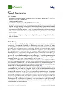
lems otherwise encountered in testing digital systems. It combines concepts of both built-in test (BIT) and self-test (ST) in one termed built-in self-test (BIST). In BIST, test generation, test application and response verification are all accomplished through built-in hardware, which allows different parts of a chip to be tested in parallel, reducing the required testing time besides eliminating the need for external test equipment. As the cost of testing is becoming a major component of the manufacturing cost of a new product, BIST reduces manufacturing, test, and maintenance costs, and improves diagnosis. Several companies like Motorola, AT&T, and IBM have included BIST in their products. For example, the Motorola 68020 microprocessor is tested using BIST techniques. The microcode ROM is self-tested in the Intel 80 386 microprocessor. Similarly, AT&T has incorporated BIST into more than 200 chips. A typical BIST environment as shown in Fig. 1 uses a test pattern generator (TPG) that sends its outputs to a CUT, and output streams from the CUT are fed into a test data analyzer. A fault is detected if the circuit response is different from that of the fault-free circuit. The test data analyzer is comprised of a response compaction unit (RCU), a storage for the fault-free response of the CUT, and a comparator. In order to reduce the amount of data represented by the fault-free and the faulty CUT responses, data compression is used to create signatures (short binary streams) from the CUT and its corresponding fault-free circuit. Signatures are compared and faults are detected if a match does not occur. BIST techniques may be used during normal functional operating conditions of the unit under test (on-line testing), as well as when a system is not carrying out its normal functions (off-line testing). In the case where, detecting real-time errors is not that important, systems, boards, and chips can be tested in off-line BIST mode. BIST techniques use pseudorandom or pseudoexhaustive test pattern generators, or on-chip storing of reduced test sets. Today, testing logic circuits exhaustively is no longer used, since only a few test patterns are needed to ensure full fault coverage for stuck-type faults. Reduced pattern test sets can be generated using algorithms such as FAN, and others. Built-in test generators can often generate such reduced test sets at low cost, making BIST techniques suitable for on-chip self-testing. This paper focuses on the response compaction process of built-in self-testing techniques which translates into a process of reducing the test response to a signature. Instead of comparing bit-by-bit the fault-free responses to the observed outputs of the CUT as in conventional testing methods, the observed signature is compared to the correct one, thereby reducing the storage needed for the correct circuit responses. The test data analyzer consists of a compaction unit, a comparator, and a storage (memory device). The compaction unit can be divided into a
0018–9456/00$10.00 © 2000 IEEE
DAS et al.: SPACE COMPRESSION REVISITED
space compaction unit and a time compaction unit. In general, input sequences coming from a CUT are fed into a space ; compactor, providing output streams of bits such that most often, test responses are compressed into one sequence . Space compaction brings a solution for the problem of achieving high-quality built-in self-testing of complex chips without monitoring a large number of internal test points. It reduces testing time and area overhead by merging test sequences coming from these internal test points into a single stream of bits. This single bit stream of length is fed into a time compactor and is obtained at the output. The a shorter one of length extra logic representing the compaction circuit must be as simple as possible, to be easily embedded within the circuit under test, and should not introduce signal delays that affect either the test execution time or the normal functionality of the circuit being tested. In addition, the length of the signature must be as short as it can be in order to minimize the amount of memory needed to store the fault-free signatures. Also, signatures obtained from faulty output responses and their corresponding fault-free signatures should not be the same, which unfortunately is not always the case. A fundamental problem with compaction techniques is error masking or aliasing [13] which occurs when the signatures of a faulty output response map to the fault-free signature, usually calculated by identifying a good circuit, applying test patterns to it, and then having the compaction unit generate the fault-free reference. Aliasing causes loss of information, which affects the testing quality of BIST and reduces the fault coverage (the number of faults detected, after compaction, over the total number of injected faults). Several methods have been suggested for computing the aliasing probability. The exact computation of this aliasing probability is known to be an NP-hard problem. In practice, high fault coverage, over 99%, is required and therefore, any space compression technique which maintains more percentage error coverage information would have to be considered for investigation. This paper considers the general problem of designing and analyzing efficient space compression techniques for built-in self-testing of VLSI circuits using compact test sets. The techniques are based on identifying certain inherent properties of the test output responses of the CUT and the knowledge of failure probabilities. The mergeability criteria of output sequences are developed utilizing the concepts of Hamming distance and sequence weights for a pair of outputs as well as an arbitrary number of outputs (generalized mergeability), and the effect of failure probabilities on the mergeability criteria is analyzed as well. The techniques proposed achieve a very high fault coverage for single stuck-line faults, with low CPU simulation time, and acceptable hardware overhead, as evident from extensive simulation results on ISCAS 85 combinational benchmark circuits, under conditions of both stochastic independence and dependence of single and multiple line errors. II. SPACE COMPRESSION APPROACH The space compression techniques proposed in the paper are basically an extension of the hybrid space compression (HSC) proposed initially by Li and Robinson [6], and the dynamic
691
space compression (DSC) subsequently put forward by Jone and Das [3]. The HSC uses AND, OR, and XOR gates to implement an output compaction tree to compress the multiple outputs of the CUT to a single line. In the DSC, instead of assigning static values for the probabilities of single and double line errors, these values are actually dynamically estimated based on the CUT structure, viz., on the number of single lines and shared lines connected to an output during the computation process. The techniques as developed herein, on the other hand, use AND (NAND), OR (NOR), and XOR (XNOR) gates as appropriate to design a compaction tree that also compresses the outputs of the CUT to a single line, but based on criteria of sequence mergeability utilizing concepts of Hamming distance and sequence weights (second-order as well as th-order). The logic functions selected to construct the compaction tree are determined by the characteristics of the sequences that form inputs to the various gates. The mergeability criteria are initially developed on the assumption of stochastic independence of single and double line errors and then of single and multiple line errors. On the other hand, if the stochastic independence is not assumed, it was observed that the probability of error occurrence plays a very significant role in the selection of gates for merger of either a pair or a number of sequences in many cases. In the latter case of stochastic dependence, the selection of appropriate output lines for merger is based on calculating the detectable error probability estimates (both second-order and th-order) Es. The gate selection criteria may, however, remain unchanged under certain special conditions of probability assignments for single line and double line errors, based on the computation of detectable error probability estimates, as against the selection criteria under the condition of stochastic independence. III. SEQUENCE CHARACTERIZATION AND MERGEABILITY OF RESPONSE DATA OUTPUT FOR SPACE COMPACTION The principal idea in space compaction is to compress functional test outputs of the CUT possibly into one single test response to derive the signature without sacrificing too much information. The logic function to be selected to build the compaction tree is essentially determined by the characteristics of the sequences which are inputs to the gates based on some mergeability criteria to be satisfied. The basic theme of the suggested approaches in this paper is to select a suitable gate to merge either two or any arbitrary number of candidate output lines of the CUT under conditions of stochastic independence and stochastic dependence of line errors, using sequence characterization developed in the paper. In the following sections the mathematical basis of these approaches is first given with appropriate notations and terminologies. A. Sequence Weights and Derived Sequences represent a pair of output sequences of a CUT Let of length , where the length is the number of bit positions and . Let represent the Hamming distance in (the number of bit positions in which and between and differ). , Definition 1: The first-order 1-weight, denoted by of a sequence , is the number of 1s in the sequence. Similarly,
692
IEEE TRANSACTIONS ON INSTRUMENTATION AND MEASUREMENT, VOL. 49, NO. 3, JUNE 2000
the first-order 0-weight, denoted by , of a sequence , is the number of 0s in the sequence. with Example 1: Consider an output sequence pair and . The length of both . The Hamming distance between output streams is 8 and is . The first-order 1-weights and and are , , 0- weights of , and , respectively (Fig. 1). Property 1: For any sequence , it can be shown that . given in Example For the output sequence and . There1, we have found that . fore, it is obvious that of Definition 2: Consider an output sequence pair equal length . Then the sequence pair derived by discarding the bit positions in which the two sequences differ (and indicated by a dash -) is called the second-order derived sequence pair, . In the rest of the paper, we will denote the derived sequence , and of a sequence by , its first-order 0-weight by . its first-order 1-weight by given in Example 1, = Example 2: For (00-01-10 , 00-01-10 . The first-order 1- weights and 0-weights are: , , of the derived pair , and . Property 2: For any second-order derived sequences , we have and . As depicted in Example 2, for the same output sequence pair given in Example 1, we have shown that and . By the above property, when no ambiguity arises, we will denote 0- and 1- weights for the derived sequence pair by simply and , respectively. The length of the derived sequence where . pair will be denoted by is always zero, we will simply use Also, since to denote . That is, for in Example 1, = = (00-01-10), and (00-01-10), . Therefore, and . Property 3: For every distinct pair of output sequences at the output of a CUT, the corresponding derived pair of equal length is distinct. but Two derived sequence pairs may have the same length they are still distinct and not identical. and Property 4: Two derived sequence pairs of original output streams pairs and , are identical. Thereby, respectively, having the same length , if and only if, . However, in general, it is not expected that any two distinct pairs of sequences at the output of the CUT will be identical and hence the possibility of the corresponding derived pairs being identical is also remote. We can extend the concept of 1-weight and 0-weight to deal . with sequences sequences , each of Definition 3: For length , let the sequences have 1s in identical bit positions (the sequences each might have 1s in other positions besides positions). Then, the th-order 1-weight of the these
Fig. 1.
Block diagram of the BIST environment.
sequences in the group is given by the number of bit positions in which all the sequences have 1s, which is in this case. sequences , each of Definition 4: For length , the th-order 0-weight is defined in the same way as the th-order 1-weight and corresponds to the number of bit positions in which all the sequences have 0s. as Example 3: Consider three sequences of length , , and given: . The third-order 1-weight of , is since the sequences , and agree and in bit positions 2,9,10,11,12 having 1s (counting from right). , and has 1s in other Note that each of the sequences bit positions besides bit positions 2,9,10,11,12. The third-order since all three sequences have 0s in bit 0-weight is positions 1 and 8 (counting from right). and an We will denote an th-order 1-weight by th-order 0-weight by , where the first subscript in each case corresponds to the sequence number or order, while the second subscript gives the binary digit corresponding to the weight. sequences , each of Definition 5: For , the th-order derived sequences, denoted by length , respectively, are obtained by deleting the bit positions in which at least two of the sequences differ and replacing the bit positions with a dash (-). , and Example 4: For the three sequences of the previous example, we have the derived sequences: , , . For these derived sequences, and and . we have and the Property 5: If the th-order 1-weight is th-order 0-weight is of the derived sequences in a bundle, then
where , called the residue, is the number of bit positions in which at least two of the sequences in the bundle have different entries, and the corresponding sets of derived sequences have dash (-) entries. IV. GATE SELECTION UNDER PAIRWISE MERGEABILITY In this section we will briefly summarize the key results concerning pairwise mergeability of response data output of a CUT in the design of space compactors. These will be provided in the form of certain theorems without proofs under conditions of both stochastic independence and stochastic dependence of
DAS et al.: SPACE COMPRESSION REVISITED
line errors, of which the details could be found in [14]. Generally space compression has been accomplished using XOR gates in cascade or in tree structure. In [1] and [14], a combination of both cascade and tree structures (cascade-tree) has been adopted as the framework comprised of AND (NAND), OR (NOR) and XOR (XNOR) operators. The gate selection was primarily based on mergeability criteria that use the properties of Hamming distance, sequence weights, and derived sequences, together with the concept of detectable error probability estimates [6] for a two-input logic function, given two input sequences of length , under conditions of stochastic dependence of single and double line errors at the output of a CUT. A. Pairwise Merger Under Stochastic Independence of Line Errors , , , and as four output and be sequence streams of a CUT. Let , their cortwo distinct output pairs, and responding derived sequence pairs, respectively, such that 00-01-10 , 00-01-10 and 0000– –11 , 0000– –11 . Both derived sequence pairs have the same but they are not identical. length of length Theorem 1: An output sequence pair and Hamming distance is XOR (XNOR) gate mergeable if which is greater the maximum number of errors detected is than or equal to the maximum number of errors detected by (AND/NAND) or OR (NOR) gates AND (NAND) gates (OR/NOR), when used for merger. of length Theorem 2: For any output sequence pair and Hamming distance , an OR (NOR) gate or an AND (NAND) gate may be used for merger if the maximum number where . of errors detected is Theorem 3: An AND (NAND) gate may be selected for of length with merging an output sequence pair , if and only if, and Hamming distance Consider
AND/NAND
Theorem 4: An OR (NOR) gate may be selected for merger of length with Hamming of an output sequence pair , if and only if, and distance OR/NOR
Corollary 4.1: However, if , either OR (NOR) or AND (NAND) gate may be used for merger. of length Theorem 5: An output sequence pair and Hamming distance needs to be merged with an AND (AND/NAND) is maximized (NAND) gate, if and only if, sequence pairs for an -output CUT. over of length Theorem 6: An output sequence pair and Hamming distance needs to be merged with an OR (OR/NOR) is maximized over (NOR) gate, if and only if, sequence pairs for an -output CUT.
693
Theorem 7: An output sequence pair is AND (NAND) gate mergeable, if and only if, Theorem 8: An output sequence pair is OR (NOR) gate mergeable, if and only if,
of length . of length .
B. Pairwise Merger Under Stochastic Dependence of Line Errors In order to consider the role of probability on error occurrence and its effect on sequence mergeability, Li and Robinson [6] defined a parameter called the detectable error probability estimate for a two-input logic function, given two input sequences of length , as follows (in the paper we call it second-order , error probability estimate): where is the probability of single error effect felt at the output of the CUT, is the probability of double error effect felt at the is the number of single line errors at the output of the CUT, is the number of double output of gate , if gate is used and line errors at the output of gate , if gate is used. Based on the of Li and Robinson as detectable error probability estimate given above, the following results are derived that profoundly influence the selection of gates for merger. of length Theorem 9: For an output sequence pair and Hamming distance , an AND( NAND) gate is preferable to an XOR (XNOR) gate if . Corollary 9.1: On the other hand, an XOR (XNOR) gate is . selected if of length Theorem 10: For an output sequence pair and Hamming distance , an OR (NOR) gate is preferable to an XOR (XNOR) gate if . Corollary 10.1: On the other hand, an XOR (XNOR) gate is . selected if However, the probability does not play any role in the selection between AND (NAND) and OR (NOR) gates if we use the empirical formula of Li and Robinson. The undernoted theorem states the condition that determines the selection criteria between AND (NAND) and OR (NOR) gates. of length Theorem 11: For an output sequence pair and Hamming distance , an AND (NAND) gate is prefer. able to an OR (NOR) gate if Corollary 11.1: An OR (NOR) gate is selected if, on the . other hand, The proofs of the above theorems along with other relevant details including algorithms for selection of the response data outputs and simulation results on ISCAS 85 combinational benchmark circuits are given in [14] and are not repeated here. Our objective in the subject paper is to rather discuss the case of generalized mergeability in greater details, as the subsequent sections will demonstrate. V. GATE SELECTION UNDER GENERALIZED MERGEABILITY We now consider the case of generalized sequence mergeability under conditions of both stochastic independence and stochastic dependence of multiple line errors occurring at the output of a CUT in the design of the desirable compaction tree. The following definitions are relevant.
694
IEEE TRANSACTIONS ON INSTRUMENTATION AND MEASUREMENT, VOL. 49, NO. 3, JUNE 2000
Definition 6: If sequences at the output of a CUT are grouped together having certain th-order 1-weight or 0-weight, then the process will be termed bundling and the grouped sequences will be termed bundled sequences. Whenever there will be bundling of a number of sequences, we will say that we are working under the bundling constraint. , is the Definition 7: The error multiplicity, denoted by number of simultaneous errors that can occur at the outputs of a CUT or the number of lines at the output of a CUT that can be faulty simultaneously. We next discuss our pertinent results in the case of generalized mergeability of response data output assuming stochastic independence of line errors (multiple). A. Generalized Mergeability Under Stochastic Independence of Multiple Line Errors Theorem 12: On the assumption of stochastic indepenoutput sequences dence of errors for a bundled set of each of length at the output of a CUT, the maximum number of possible errors with all possible is . multiplicities of errors sequences at the Theorem 13: For , let the derived sequences output of a CUT of length , have th-order 1-weight and 0-weight, and , respectively, and let be the residue. The total sequences number of faults detected when are merged together by using an -input AND (NAND) gate is AND/NAND
where ( represents the number of error mul, and represents the number of tiplicities of errors corresponding to the th-order residue position of 0s. sequences at the Theorem 14: For , let the derived sequences output of a CUT of length , have th-order 1-weight and 0-weight, and , respectively, and let be the residue. sequences The total number of faults detected when the are merged by using an -input OR (NOR) gate is OR/NOR
where represents the number of 1-error , represents multiplicities of , and the number of 0-error multiplicities of represents the number of errors corresponding to the th-order residue position of 0s, being even. sequences at the Theorem 16: For , let the derived sequences be output of a CUT of length . Let the th-order 1-weight be and th-order 0-weight be . For merger of the sequences, an -input AND (NAND) gate will be preferable to an -input OR (NOR) gate for maximizing error detection if
Corollary
16.1: For the merger of sequences of length , th-order 1-weight and th-order 0-weight , an -input OR (NOR) gate is preferable to an -input AND (NAND) gate if
Theorem 17: For sequences at the , let the derived sequences be output of a CUT of length . In addition, let the th-order 1-weight be and th-order 0-weight be . For merger of sequences, an -input AND(NAND) will be preferable to an -input XOR (XNOR) gate for maximizing error detection if
Corollary 17.1: For merger of sequences of length , th-order 1-weight and th-order , an -input XOR( XNOR) gate is preferable to 0-weight an -input AND( NAND) gate if or Theorem 18: For sequences at the , let the derived sequences be output of a CUT of length . In addition, let the th-order 1-weight be and th-order 0-weight be . For merger of sequences, an -input OR (NOR) gate will be preferable to an -input XOR (XNOR) gate for maximizing error detection if or
where represents the number of error muland represents the number of tiplicities of errors corresponding to the th-order residue position of 0s. sequences at the Theorem 15: For , let the derived sequences output of a CUT of length , have th-order 1-weight and 0-weight, and , respectively, and let be the residue. sequences The total number of faults detected when the are merged by using an -input XOR (XNOR) gate is XOR/XNOR
Corollary 18.1: For merger of sequences of length , th-order 1-weight and th-order , an -input XOR (XNOR) gate is preferable to 0-weight an -input OR (NOR) gate if or Theorem 19: For sequences at the , let the derived sequences be output of a CUT of length . In addition, let the th-order 1-weight be and th-order 0-weight be . In the extreme case when and
DAS et al.: SPACE COMPRESSION REVISITED
695
the total faults detected by -input AND (NAND), OR (NOR) and XOR (XNOR) gates are, respectively, as follows: AND/NAND XOR/XNOR
OR/NOR
and
The theorems are very important in the selection of the best subsets of output sequences in maximizing error detection at the CUT output during space compaction. The proofs of these theorems are intentionally avoided for the sake of brevity though the theorems are retained for completeness. Some of the results in the said context can also be found in [1]. VI. IMPLEMENTATION STRATEGY For the implementation of the generalized mergeability criteria as outlined in the results of the preceding section to construct the space compactor, the algorithm was developed. The algorithm was written in the C language, and was executed on ISCAS 85 combinational benchmark circuits using fault simulation and fault detection programs ATALANTA, FSIM and COMPACTEST. The steps of the algorithm are given next followed by a simple illustrative example.
A) Separation Criteria of Sequences for AND (NAND) and OR (NOR) Gates A1) All original sequences are separated in two lists: ANDlist, ORlist as follows (NAND and NOR gate listings with AND and OR gates, respectively, are omitted in subsequent descriptions of the algorithm). are sent to • All sequences that have number of 1s is the length of the sequence). the ANDlist (where are sent to • All sequences that have number of 1s the ORlist. where that have A2) Sequences are sent to the appropriate list where there number of 1s = is a potential grouping. This is done according to the following algorithm: . Let us consider the case where bitwise AND [all sequences • Execute the operation: of ANDlist], then retain and count the outputs that have ; let “andMatch” be that number. number of 1s = inverted] bitwise AND [all sequences of • Execute ORlist inverted], then retain and count the outputs that ; let “orMatch” be that number. have number of 1s = • Now, compare “andMatch” and “orMatch” numbers, to the largest list among them, where a potential send grouping exists. Here inversion means one’s complement. For example, if , then inverted] = 100 110 000. is the length of a sequence. B) Stage 1 B1) Obtaining the list of sequences having Best 1’s or 0’s Grouping:
• From the ANDlist, group sequences according to an algorithm that takes into consideration , i.e. , in case of AND gate: : number of matching 1s in the same bit positions of all candidate sequences. : number of sequences that have matching of 1’s bits in common. • Detailed explanation of this algorithm is given as follows: overrides . In other words, the group that has B1.1) is the best group as long as . the maximum value of B1.2) The best grouping between two groups that have the is the one that has the bigger value. same value of B2) The same algorithm can be applied to the ORlist but we should replace 1 by 0. B3) Mergeability Criteria: Assume the following: : Number of matching 1s in the same bit positions of all candidate sequences. : Number of matching 0s in the same bit positions of all candidate sequences. : the best grouping of sequences B3.1) For obtained from B1) is merged together with an AND gate only. The resulting output is sent back to the AND sublist. : the best grouping of B3.2) For sequences obtained from B1) is merged together with AND and XOR gates (XNOR is omitted from discussions). The resulting case output is sent either to AND, OR, or XOR (when exists) sublists. All the resulting trees of gates are found by using a recursive algorithm. : the best grouping of sequences B3.3) For obtained from B2) is merged together with an OR gate only. The resulting output is sent back to the OR sublist. : the best grouping of B3.4) For sequences obtained from B1) is merged together with OR and XOR gates. The resulting output is sent either to AND, OR, or case exists) sublists. All the resulting trees of XOR (when gates are found by using a recursive algorithm. B4) Sorting the output sequence after merging with an XOR gate: If the output sequence has: : the sequence is sent to the AND • Number of 1s sublist of candidates. : the sequence is sent to the OR • Number of 1s sublist of candidates. : the sequence is sent either to the • Number of 1s = AND or OR sublists according to the algorithm described in A2). C) Stage Two and Intermediate Stages • Repeat the same steps as in Stage A. • Intermediate stages exist as long as there are still sequences which can be grouped by either AND, AND (XOR), OR, OR (XOR) gates. D) Last Stage (XOR Processing) The obtained sequences that cannot be grouped by AND or OR gates are merged together by the XOR gate. At this point, we get the last output sequence of the whole list of sequences.
696
IEEE TRANSACTIONS ON INSTRUMENTATION AND MEASUREMENT, VOL. 49, NO. 3, JUNE 2000
The following rules are important for the clarification of the first algorithm. Rule: Assume we have two 1’s groupings of sequences with and . The following rule is applied to obtain the optimal solution (best grouping out of both of them): a) Weight “ ” takes advantage over (overrides) number of sequences “ .” In other words, the group that has the is the best solution. maximum value of , our optimal solution is the group that has b) If the maximum value of . and , our optimal solution is c) If either one. This rule can be generalized for several groups of sequences, i.e., sequences. Consider the following sequences: . is the group of sequences which has sequences that have matching of 1’s bits, and is that the group of sequences which has sequences have matching of 1’s bits. Three cases can be considered as follows: group is better than group . a) If group is better than group . b) If and group is better than c) If group . The same procedure can be followed for matching 0s of bits. Example 5: Find the FIRST best gate selection for the following six bit streams. seq seq seq seq seq seq seq In the above example, we have three groups of 1’s and five and groups of 0’s to be considered, where . All possibilities of 1’s groupings are: First 1 s group seq
seq
seq
seq
seq
seq
Second 1 s group Third 1 s group All possibilities of 0’s groupings are: First 0 s group seq
seq
Second 0 s group seq
seq
seq
seq
seq
seq
seq
seq
Third 0 s group Fourth 0 s group Fifth 0 s group seq
From all the above possibilities, according to the highest weight, only two groups are to be considered: , (seq 1, • Second 1’s group: seq 2, seq 3) and , (seq 0, • Third 1’s group: , seq 6). Solution: By applying the general rule and since , we select the third 1’s group (seq 1, seq 2, seq 3) as the BEST group to be merged by an AND gate.
In order to understand the process to obtain the “Best Group,” the following definitions, categories of grouping and stages of processing are provided. Definition and initialization of parameters: • max : a variable which denotes the maximum number of matching bits (can be 0 or 1 according to the kind of grouping taken into consideration) in the same bit positions obtained so far in the process of getting the BEST GROUP. • max : a variable which denotes the maximum number of sequences that have max matching of (1s or 0s according to the kind of grouping taken into consideration) bits in common obtained so far in the process of getting the BEST GROUP. As a first step, we initialize both max and max to zero. Stages of processing: At the first stage, “Selecting the Best Group” subalgorithm (explained later) is applied by starting with seq0 going through each of: seq1, seq2, , seq . At the second stage, “Selecting the Best Group” subalgorithm is applied by starting with seq1 going through each of the fol, seq . At the th stage, “Selowing sequences: seq2, seq3, lecting the Best Group” algorithm is applied by starting with ) going through each of the following sequences: seq , seq( , seq . seq( The last stage of processing during the execution of the algo) going through seq . rithm starts at seq( Categories of groupings: The various kinds of groupings are defined and classified as follows: max , it means Cat [1] Bad Grouping: If resulting that we must exclude this sequence from grouping under the same stage. max or Cat [2] Good Grouping: If resulting max ], it means that [resulting = max and resulting we continue processing in the same stage. Cat [3] Better Grouping: It has the same conditions as in Good Grouping. In addition, it is the last good grouping found in a stage. The grouping is considered as a candidate for the “Best Grouping." and Cat [4] Best Grouping: It has the maximum of parameters found after going through all the stages and so it is the best group of all the stages. Subalgorithm to select the “BEST GROUP”: In stage 1, we start processing the operation with seq0. 1) To obtain the matching of 1s in each bit position we which has ( ). do: (seq0 AND seq1) = (resulting ) with max and Now we compare
DAS et al.: SPACE COMPRESSION REVISITED
2)
3)
4)
5)
if needed (when = max ), we compare (resulting ) with max and record the highest of both, , max ]. We put it in max , and we i.e., MAX[ put MAX[ , max ] in max . max then (seq0 , seq1) is a bad • If resulting grouping according to Cat [1], and we restart 1) for seq0 and seq2. • If (seq0, seq1) is a good grouping according to Cat [2], we can say that (seq0, seq1) is the best group so far. Then we go to 2). AND seq2) = which has Now we execute: ). Then we compare (resulting ) with ( = max ), we commax and if needed (when (resulting ) with max and record the highest pare of both, i.e., MAX[ , max ]. We put it in max and we put MAX[ , max ] in max . max then (seq0, seq1, seq2) is • If resulting a bad grouping according to Cat [1] and we restart and seq3. 2) for • If ( , seq2) is a good grouping according to Cat [2], we can say that ( , seq2) is the best group so far. Then we go to 3). AND seq3) = which has Now we execute: ( ). Then we compare (resulting ) with ( (obtained in step 2) and if needed (when max = max ) we compare (resulting ) with max (obtained in step 2) and record the highest of both, i.e., MAX[ , max ]. We put it in maxW and we put MAX[ , max ] in max . max (seq0, seq1, seq2, seq3) • If resulting is a bad grouping according to Cat [1], we restart 3) and seq4. for • If ( , seq3) is a good grouping according to Cat [2], we can say that ( , seq3) is the best group so far. Then we go to the next step. We repeat the above steps until we exhaust all sequences starting with sequence 0. Whenever we find the “better grouping” according to Cat [3] in the first stage (steps: 1, 2, 3), we compare its resulting parameters to the first grouping of the second stage which starts with sequence 1. We repeat step 4) for all the existing stages. At the last stage, we obtain the optimal grouping which is the “best grouping for the whole list of sequences” according to Cat [4]. This step is achieved using a recursive method.
A. Mergeability Criteria The main idea for merging a set of sequences by AND (NAND), OR (NOR) and XOR (XNOR) gates can be summarized as one of finding if this set of sequences satisfies one of the following criteria: , the obtained group sequences are merged • If together with an AND (NAND) gate only. , the obtained group sequences are • If merged together with an OR (NOR) gate only.
697
• If and , the remaining sequences which cannot be merged by either AND (NAND) or OR (NOR) gates are merged together with the XOR (XNOR) gate only at this level. VII. SPACE COMPACTION UNDER GENERALIZED MERGEABILITY BASED ON STOCHASTIC DEPENDENCE OF MULTIPLE LINE ERRORS In this section, we will present generalized mergeability criteria for merging an arbitrary number of response data outputs of the CUT under stochastic dependence of multiple line errors. In order to do that, we first extend the definition of second-order as defined earlier to detectable error probability estimate cover the case of sequences. We state the following obvious theorems without proof. Theorem 20: The second-order detectable error probability when two sequences and of length are estimate merged by using an AND (NAND) gate is AND/NAND where is the Hamming distance between the two sequences. Theorem 21: The second-order detectable error probability estimate when two sequences and of length are merged by using an OR (NOR) gate is OR/NOR with being the Hamming distance between the sequences. Theorem 22: The second-order detectable error probability when two sequences and of length are estimate (XOR/XNOR) = merged by using an XOR (XNOR) gate is . A. Derivation of the th-Order Detectable Error Probability Estimate for Individual Gates In this section, we will determine the th-order detectable for AND (NAND), OR (NOR) error probability estimate and XOR (XNOR) gates. They are derived for the case when is odd. The expressions for s will be very much similar is even. when Let , each of length , be the output sequences at the output of a CUT. Let the corresponding th-order derived sequences be , having th-order 1-weight and 0-weight, and , respectively. be the probability of -line errors. Let , Realistically, one can assume that and . Let be the residue, that is, the number of bit positions in which at least two of the sequences be the number of in the bundle have different entries. Let columns in the bundle set with vertical 1-weight equal to . Let us denote the binomial coefficient ( ) simply by the symbol or . Example 6: Consider the following five sequences of length each:
698
IEEE TRANSACTIONS ON INSTRUMENTATION AND MEASUREMENT, VOL. 49, NO. 3, JUNE 2000
In this example, the 5th-order 1-weight is and the . The residue is equal to 6 since 5th-order 0-weight is there are 6 bit positions in which at least two sequences differ. , , , , The vertical 1-weights are . and Theorem 23: The th-order detectable error probability esare merged by using timate when sequences an -input AND (NAND) gate is
Theorem 24: The th-order detectable error probability esare merged by using timate when sequences , an -input OR (NOR) gate is OR/NOR
AND/NAND Proof: Proof: AND/NAND
OR/NOR
DAS et al.: SPACE COMPRESSION REVISITED
Theorem 25: The th-order detectable error probability esare merged by using timate when sequences , an -input XOR (XNOR) gate is XOR/XNOR Theorem 26: In general, for two -input gates and , is preferable to , if and only if, . Theorems 25 and 26 are obvious and proofs are omitted. B. Implementation The heuristic approach has been adopted and implemented in the following algorithm in order to get results within an acceptable CPU time. The heuristic approach is very useful in this case since a closed-form expression of the th-order detectable error probability estimates can be computationally intensive.
A1) From all the output sequences, select a group of sequences having the largest th-order 0-weight. Then select sequences having the largest th-order another group of 1-weight. A2) Choice between selected 1-weight and 0-weight groups In order to make a choice between the largest groups based on 1’s grouping or 0’s grouping, let us consider the following example. Suppose we obtained from step A1) a 0’s grouping and a 1’s grouping which have as weights and numbers of sequences , ) and ( , ), respectively. The selection of the ( best group between both groups is done according to the following rule: (weight) overrides (number of sequences) which a. is the means the group that has the maximum value of best solution. , the best group is the group that has the b. If largest value of . and , the best group is either c. If one. In the implementation, the th-order 1-weight is chosen. A3) Choice between (AND/NAND, OR/NOR) gates A3.1) If 1-weight is chosen and : • Compute , then the AND gate is chosen over • If OR, but it still has to be compared with XOR. , then compute both the formulas: • If
699
but it still has to be compared with the XOR/XNOR gate. *If [AND/NAND] [OR/NOR], then the OR/NOR gate is chosen over the AND/NAND gate, but it still has to be compared with the XOR/XNOR gate. [AND/NAND] = [OR/NOR], then either *If AND/NAND or OR/NOR gate can be chosen, but the chosen gate still has to be compared with the XOR/XNOR gate. In the implementation, the AND gate was chosen in this situation. A3.2) If 0-weight is chosen and : • Compute , then OR/NOR gate is chosen over • If AND/NAND gate, but it still has to be compared with XOR/XNOR gate. , then compute both the formulas: • If AND/NAND
OR/NOR
• Then compare them and: [AND/NAND] [OR/NOR], then the *If AND/NAND gate is chosen over the OR/NOR gate, but it still has to be compared with the XOR/XNOR gate. [AND/NAND] [OR/NOR], then the *If OR/NOR gate is chosen over the AND/NAND gate, but it still has to be compared with the XOR/XNOR gate. [AND/NAND] = [OR/NOR], then either *If AND/NAND or OR/NOR gate can be chosen, but the chosen gate still has to be compared with the XOR/XNOR gate. In the implementation, the AND gate was chosen in this situation. A4) Choice between (above chosen gate, XOR/XNOR) gates A4.1) Case 1 (AND/NAND, XOR/XNOR): a) Compute: for odd for even
AND/NAND
OR/NOR
b) If , then use the AND/NAND gate (nonexhaustive approach is fulfilled). , then c) If compute
• Then compare them and: [AND/NAND] [OR/NOR], then the *If AND/NAND gate is chosen over the OR/NOR gate,
and next compute . , then use the AND/NAND gate. d) If , then use the XOR/XNOR gate. e) If
700
IEEE TRANSACTIONS ON INSTRUMENTATION AND MEASUREMENT, VOL. 49, NO. 3, JUNE 2000
f) If , then use either AND/NAND or XOR/XNOR gate. In the implementation, the XOR gate was chosen in this situation. A4.2) Case 2 (OR/NOR, XOR/XNOR): a) Compute for odd. for even. , then use the OR/NOR gate (nonexhaustive apb) If proach is fulfilled). , then c) If compute and next . , then use the OR/NOR gate. d) If , then use the XOR/XNOR gate. e) If , then use either OR/NOR or XOR/XNOR gate. f) If In the implementation, the XOR gate was chosen in this situation. A5) Apply the above procedure to the merging sequence and all the remaining sequences until we end up with only one sequence at the output. VIII. EXPERIMENTAL RESULTS To demonstrate the feasibility of the proposed space compaction schemes, independent simulations were conducted on various ISCAS 85 combinational benchmark circuits. We used ATALANTA (fault simulation program developed at the Virginia Polytechnic Institute and State University) to generate the fault-free output sequences required to construct our space compactor circuits and to test the benchmark circuits using reduced or compact test sets accompanied with a random testing session with the FSIM fault simulation program to generate pseudorandom test sets. We used the COMPACTEST program to generate reduced test sets that detect most detectable single stuck-line faults for all of the benchmark circuits. For each circuit, we determined the number of test vectors used to construct the compaction tree, the CPU time taken to construct the compactor, the number of applied test vectors, the simulation CPU time, and the percentage fault coverage by running ATALANTA and FSIM programs on a SUN Sparc 5 workstation, and COMPACTEST on an IBM aix machine, under conditions of both pairwise and generalized mergeability. For comparison purposes, we used a parity tree space compactor composed of XOR gates, that propagates errors on an odd number of inputs and is usually considered ideal for space compression. With the parity tree space compactor as reference, the novelty of the proposed schemes of constructing compaction trees is based on extensive simulation runs on ISCAS 85 combinational benchmark circuits. Many of these simulation results could be found reported in [1] and [14]. In the generalized mergeability case, the heuristic-based approach to generate the compression trees also works satisfactorily, as is obvious from the results of simulation. In the following tables we provide some experimental results in the generalized mergeability case on
ISCAS 85 benchmark circuits using FSIM, ATALANTA, and COMPACTEST. As evident, in all cases, our space compactors compare very favorably with the parity tree space compactor in terms of fault coverage and reduced CPU time. The hardware overhead of the compactors was found to be within acceptable limits (in general, within 1–5% and up to 15% in certain cases). The hardware overhead was estimated as the ratio of the weighted gate count metric, which is basically average fanins multiplied by the number of gates of the compactor and that of the total circuit comprised of the CUT and the space compactor. As a result of the conducted simulation and for some combinational circuits, we obtained several space compressors (trees). In such a situation, we selected the “best tree,” which is the tree that gave the highest fault coverage; when two or more trees had identical fault coverages, we selected the one that gave the smallest CPU time. For each ISCAS 85 combinational circuit, several variables were determined and included in tabular format. These variables are: the number of test vectors used to construct the best compaction tree, the CPU time taken to construct the best compaction tree, the number of applied test vectors corresponding to the best tree obtained, the simulation CPU time and the percentage of fault coverage by running ATALANTA, FSIM and COMPACTEST programs on a Sparc 5 SUN workstation and IBM aix machine, respectively. IX. CLASSIFICATION OF SIMULATED RESULTS All the simulation results obtained from FSIM, ATALANTA, and COMPACTEST are classified in tables and presented in the next paragraph under the following four categories: simulations without using compactors, simulations by assuming stochastic independence of line errors, simulations by considering stochastic dependence of line errors, and simulations by using the parity tree as a space compactor. In addition, we estimated the hardware overhead for all the circuits in two tables. The first table determines the percentage of hardware overhead for FSIM and ATALANTA while the second determines the same percentage for COMPACTEST. A. Simulation Results Without Using Compactors Using FSIM, ATALANTA, and COMPACTEST as fault simulators, we determined the fault coverage and the CPU simulation time required for all ISCAS 85 benchmark circuits, without using compactors. The results are shown in Tables I–III, respectively. From the above tables, we can readily conclude that ATALANTA and COMPACTEST provide almost similar fault coverage simulation results. These results are much higher than what is provided by the FSIM simulations for all ISCAS 85 circuits. Since all the simulations were conducted on the Sparc 5 SUN workstation, therefore it is perfectly legitimate to compare the CPU time of all the simulators. Having done that, we notice that FSIM provides the smallest (best) CPU simulation time for almost all circuits, while COMPACTEST provides by far the highest (worst) CPU time as compared to FSIM and ATALANTA except for circuit c17.
DAS et al.: SPACE COMPRESSION REVISITED
701
TABLE I SIMULATION RESULTS OF THE ISCAS 85 BENCHMARK CIRCUITS USING FSIM WITHOUT COMPACTORS
TABLE IV SIMULATION RESULTS AND VALUES USED TO CONSTRUCT THE BEST COMPACTION TREE OF THE ISCAS 85 BENCHMARK CIRCUITS USING FSIM AND ASSUMING STOCHASTIC INDEPENDENCE OF MULTIPLE LINE ERRORS
TABLE II SIMULATION RESULTS OF THE ISCAS 85 BENCHMARK CIRCUITS USING ATALANTA WITHOUT COMPACTORS
TABLE V SIMULATION RESULTS AND VALUES USED TO CONSTRUCT THE BEST COMPACTION TREE OF THE ISCAS 85 BENCHMARK CIRCUITS USING ATALANTA AND ASSUMING STOCHASTIC INDEPENDENCE OF MULTIPLE LINE ERRORS
TABLE III SIMULATION RESULTS OF THE ISCAS 85 BENCHMARK CIRCUITS USING COMPACTEST WITHOUT COMPACTORS
TABLE VI SIMULATION RESULTS AND VALUES USED TO CONSTRUCT THE BEST COMPACTION TREE OF THE ISCAS 85 BENCHMARK CIRCUITS USING COMPACTEST AND ASSUMING STOCHASTIC INDEPENDENCE OF MULTIPLE LINE ERRORS
B. Simulation Results by Assuming Stochastic Independence Tables IV–VI show the simulation results for all ISCAS 85 benchmark circuits by assuming stochastic independence of multiple line errors using FSIM, ATALANTA, and COMPACTEST, respectively. The number of space compressors obtained for each circuit is indicated in the last column of each table. In the case where several space compactors are obtained, we selected the space compactor (tree) that gave the highest fault coverage; when two or more compactors had identical fault coverage, we selected the one that has the smallest CPU time. It is worth mentioning that the CPU time taken to construct the best compaction tree is obtained by dividing the total CPU time computed for all trees which is obtained from the C pro-
gram simulation by the total number of trees obtained for a specific ISCAS 85 benchmark circuit. In the case of stochastic independence, obviously ATALANTA provides the best fault coverage results among all the simulators. FSIM provides the best CPU simulation time followed by ATALANTA. C. Simulation Results by Assuming Stochastic Dependence By assuming stochastic dependence of line errors, we obtained Tables VII–IX, which represent the simulation results obtained from the C program as well as the simulation results obtained from FSIM, ATALANTA, and COMPACTEST.
702
IEEE TRANSACTIONS ON INSTRUMENTATION AND MEASUREMENT, VOL. 49, NO. 3, JUNE 2000
TABLE VII SIMULATION RESULTS AND VALUES USED TO CONSTRUCT THE BEST COMPACTION TREE OF THE ISCAS 85 BENCHMARK CIRCUITS USING FSIM AND ASSUMING STOCHASTIC DEPENDENCE OF MULTIPLE LINE ERRORS
TABLE VIII SIMULATION RESULTS AND VALUES USED TO CONSTRUCT THE BEST COMPACTION TREE OF THE ISCAS 85 BENCHMARK CIRCUITS USING ATALANTA AND ASSUMING STOCHASTIC DEPENDENCE OF MULTIPLE LINE ERRORS
TABLE X SIMULATION RESULTS OF THE ISCAS 85 BENCHMARK CIRCUITS USING FSIM WITH PARITY TREE COMPACTOR
TABLE XI SIMULATION RESULTS OF THE ISCAS 85 BENCHMARK CIRCUITS USING ATALANTA WITH PARITY TREE COMPACTOR
TABLE XII SIMULATION RESULTS OF THE ISCAS 85 BENCHMARK CIRCUITS USING COMPACTEST WITH PARITY TREE COMPACTOR TABLE IX SIMULATION RESULTS AND VALUES USED TO CONSTRUCT THE BEST COMPACTION TREE OF THE ISCAS 85 BENCHMARK CIRCUITS USING COMPACTEST AND ASSUMING STOCHASTIC DEPENDENCE OF MULTIPLE LINE ERRORS
D. Simulation Results Using the Parity Tree as Space Compactor
It is worth noting here that for each grouping, which is the probability of the th line error occurrence is equal for , and it is equal to to for . This operation is computed for each grouping encountered during the execution of the algorithm described above. As far as fault coverage is concerned, ATALANTA provides the best results, while FSIM provides the best results in terms of CPU simulation time.
We also simulated all ISCAS 85 benchmark circuits with parity tree space compactors using FSIM, ATALANTA, and COMPACTEST. The obtained simulation results are given in Tables X–XII, respectively. By comparing the fault coverage of all the simulators, ATALANTA in general provides the best results followed by COMPACTEST. In terms of the CPU time results, FSIM provides the smallest (best) results followed by ATALANTA. From the simulation experiments, it is obvious that in all cases, our space compactor is comparable in all respects with the parity tree space compactor. For some circuits, we obtained
DAS et al.: SPACE COMPRESSION REVISITED
TABLE XIII ETIMATES OF THE HARDWARE OVERHEAD FOR ATALANTA OR FSIM
TABLE XIV ESTIMATES OF THE HARDWARE OVERHEAD FOR COMPACTEST
703
placed on designing aliasing free compressors. We have rather endeavored to show how the input test sets and their lengths play a role in the design of compression networks. Loss of information in general is unavoidable when the size of the output responses is reduced. In the simulation experiments we used the reduced sets of tests provided by ATALANTA and COMPACTEST for ISCAS 85 benchmark combinational circuits, under conditions of stochastic independence and dependence of single and multiple line errors (two line errors, in fact, comes as a special case). Though the provided reduced test sets are not the minimal test sets that ensure 100% fault coverage, experimental results indicate that the designed space compressors are comparable to parity tree compactors in almost all respects. The design methods are simple and the resulting hardware overhead is low, which makes their applications in the BIST environment quite suitable. ACKNOWLEDGMENT The authors are extremely grateful to the anonymous referees and to the Guest Editor Dr. Vincenzo Piuri in particular for their many valuable suggestions that immensely helped in the preparation of this revised version of the manuscript.
better fault coverage with reduction in CPU time using our space compactor than what we have when a parity tree compactor is used. X. HARDWARE OVERHEAD Tables XIII and XIV show the hardware overhead estimates for all ISCAS 85 benchmark circuits corresponding to ATALANTA/FSIM and COMPACTEST, respectively. In order to estimate the hardware overhead, we used the ratio of the weighted gate count metric, that is, average fanins multiplied by the number of gates, of the compactor and that of the total circuit comprised of the CUT and the space compactor. As can be seen from the above tables, the hardware overhead of the best compactor for all the ISCAS 85 benchmark circuits is as small as (0.2–4.2)% in the case of ATALANTA and FSIM, and equals to 14.3% for circuit c17 (the space compactor of this circuit is composed of one gate only). For the case of COMPACTEST simulator, the hardware overhead is even smaller and it ranges from 0.01 to 3.9% and is equal to 14.3% for circuit c17. For the large circuits such as c2670, c7552, we obtained groupings of two, three, and four sequences. In the case of stochastic dependence of errors, the space compactor logical . Therefore, circuit depends on the values assigned to could change the gate composition of the correchanging sponding logical circuit. XI. CONCLUSIONS This paper presents space compaction techniques of test output responses in the context of built-in self-testing of VLSI circuits. In this research, however, no emphasis was
REFERENCES [1] S. R. Das, E. M. Petriu, T. Barakat, M. H. Assaf, and A. R. Nayak, “Space compaction under generalized mergeability,” IEEE Trans. Instrum. Meas., vol. 47, pp. 1283–1293, Oct. 1998. [2] P. H. Bardell, W. H. McAnney, and J. Savir, Built-In Test for VLSI: Pseudorandom Techniques. New York: Wiley, 1987. [3] W. B. Jone and S. R. Das, “Space compression method for built-in selftesting of VLSI circuits,” Int. J. Computer Aided VLSI Design, vol. 3, pp. 309–322, Sept. 1991. [4] M. Karpovsky and P. Nagvajara, “Optimal robust compression of test responses,” IEEE Trans. Comput., vol. C–39, pp. 138–141, Jan. 1990. [5] H. K. Lee and D. S. Ha, “On the generation of test patterns for combinational circuits,” Dept. Electrical Engineering, Virginia Polytechnic Institute and State University, Blacksburg, Tech. Rep. 12-93, 1993. [6] Y. K. Li and J. P. Robinson, “Space compression method with output data modification,” IEEE Trans. Computer-Aided Design, vol. CAD-6, pp. 290–294, Mar. 1987. [7] E. J. McCluskey, “Built-in self-test techniques,” IEEE Design and Test of Computers, vol. 2, pp. 21–28, Apr. 1985. [8] I. Pomeranz, L. N. Reddy, and S. M. Reddy, “COMPACTEST: A method to generate compact test sets for combinational circuits,” in Proc. Int. Test Conf., 1991, pp. 194–203. [9] D. K. Pradhan and S. K. Gupta, “A new framework for designing and analyzing BIST techniques and zero aliasing compression,” IEEE Trans. Comput., vol. C–40, pp. 743–763, June 1991. [10] S. M. Reddy, K. K. Saluja, and M. G. Karpovsky, “Data compression technique for test responses,” IEEE Trans. Comput., vol. C–37, pp. 1151–1156, Sept. 1988. [11] K. K. Saluja and M. Karpovsky, “Testing computer hardware through compression in space and time,” in Proc. Int. Test Conf., 1983, pp. 83–88. [12] J. Savir, “Reducing the MISR size,” IEEE Trans. Comput., vol. C-45, pp. 930–938, Aug. 1996. [13] K. Chakrabarty, “Test Response Compaction for Built-In Self-Testing,” Ph.D. dissertation, Dept. Computer Science and Engineering, University of Michigan, Ann Arbor, 1995. [14] M. H. Assaf, “Space Compactor Design for Built-In Self-Testing of VLSI Circuits from Compact Test Sets Using Sequence Characterization and Failure Probabilities,” M.A.Sc. thesis, Dept. Electrical Engineering, University of Ottawa, Ottawa, Ontario, Aug. 1996. [15] N. A. Touba and E. J. McCluskey, “Synthesis of mapped logic for generating pseudorandom patterns for BIST,” in Proc. Int. Test Conf., 1995, pp. 674–682.
704
IEEE TRANSACTIONS ON INSTRUMENTATION AND MEASUREMENT, VOL. 49, NO. 3, JUNE 2000
Sunil R. Das (M’70–SM’90–F’94) received the B.Sc. degree (Honors) in physics and the M.Sc. degree (Tech.) and the Ph.D. degree in radiophysics and electronics from the University of Calcutta, Calcutta, West Bengal, India. He is a Professor of Electrical and Computer Engineering at the School of Information Technology and Engineering, University of Ottawa, Ottawa, Ont., Canada. He previously held academic and research positions with the Department of Electrical Engineering and Computer Sciences, Computer Science Division, University of California, Berkeley, the Center for Reliable Computing (CRC), Computer Systems Laboratory, Department of Electrical Engineering, Stanford University, Stanford, CA (on sabbatical leave), the Institute of Computer Engineering, National Chiao Tung University, Hsinchu, Taiwan, R.O.C., and the Center of Advanced Study (CAS), Institute of Radiophysics and Electronics, University of Calcutta. He has published extensibly in the areas of switching and automata theory, digital logic design, threshold logic, fault-tolerant computing, microprogramming and microarchitecture, microcode optimization, applied theory of graphs, and combinatorics. He edited jointly with P. K. Srimani a book entitled Distributed Mutual Exclusion Algorithms (Los Alamitos, CA: IEEE Computer Society Press, 1992) in the Technology Series. He is also the author jointly with C. L. Sheng of a text on Digital Logic Design being published by Ablex Publishing Corporation. Dr. Das served in the Technical Program Committees and Organizing Committees of many IEEE and non-IEEE International Conferences, Symposia, and Workshops, and also acted as session organizer, session chair, and panelist. He was elected one of the delegates of the prestigious “Good People, Good Deeds” of the R.O.C. in 1981 in recognition of his outstanding contributions in the field of research and education. He is listed in the Marquis Who’s Who Biographical Directory of the Computer Graphics Industry, Chicago, IL (First Edition, 1984). He served as the Managing Editor of the IEEE VLSI Technical Bulletin, a publication of the IEEE Computer Society Technical Committee on VLSI, and also as an Executive Committee Member of the IEEE Computer Society Technical Committee on VLSI. He is currently an Associate Editor of the IEEE TRANSACTIONS ON SYSTEMS, MAN, AND CYBERNETICS (now of Part A, Part B, and Part C), an Associate Editor of the IEEE TRANSACTIONS ON INSTRUMENTATION AND MEASUREMENT and a Member of the Editorial Board and a Regional Editor for Canada of the VLSI Design: An International Journal of Custom-Chip Design, Simulation and Testing (Gordon and Breach Science Publishers, Inc., NY). He is a former Administrative Committee (ADCOM) Member of the IEEE Systems, Man, and Cybernetics Society, a former Associate Editor of the IEEE TRANSACTIONS ON VLSI SYSTEMS (for two consecutive terms), a former Associate Editor of the SIGDA Newsletter, the publication of the ACM Special Interest Group on Design Automation, and a former Associate Editor of the International Journal of Computer Aided VLSI Design (Ablex Publishing Corporation, Norwood, NJ). He was the Associate Guest Editor of the IEEE JOURNAL OF SOLID-STATE CIRCUITS Special Issues on Microelectronic Systems (3rd and 4th Special Issues), and Guest Editor of the International Journal of Computer Aided VLSI Design (September 1991) as well as VLSI Design: An International Journal of Custom-Chip Design, Simulation and Testing (March 1993 and September 1996), Special Issues on VLSI Testing. He is currently Guest Editing another Special Issue of the journal: VLSI Design in the area of VLSI Testing scheduled for December 2000. He was elected a Fellow of the IEEE in 1994 for contributions to switching theory and computer design. He is also a Member of the ACM. He is the 1996 recipient of the IEEE Computer Society’s highly esteemed Technical Achievement Award for his pioneering contributions in the fields of switching theory and modern digital design, digital circuits testing, microarchitecture and microprogram optimization, and combinatorics and graph theory. He is also the 1997 recipient of the IEEE Computer Society’s Meritorious Service Award for excellent service contributions to IEEE Transactions on VLSI Systems and the Society, and was elected a Fellow of the Society for Design and Process Science, USA, in 1998 for his accomplishments in integration of disciplines, theories, and methodologies, development of scientific principles and methods for design and process science as applied to traditional disciplines of engineering, industrial leadership and innovation, and educational leadership and creativity. In recognition as one of the distinguished core of dedicated volunteers and staff whose leadership and services made the IEEE Computer Society the world’s preeminent association of computing professionals, he was made a Golden Core Member of the Computer Society in 1998. He is also the recipient of the IEEE Circuit and Systems Society’s Certificates of Appreciation for services rendered as Associate Editor of the IEEE TRANSACTIONS ON VERY LARGE SCALE INTEGRATION SYSTEMS (1995–1996 and 1997–1998), and of the IEEE Computer Society’s Certificates of Appreciation for services rendered to the Society as Member of the Society’s Fellow Evaluation Committee, once in 1998 and then in 1999. He serves as a Member
of the IEEE Computer Society’s Fellow Evaluation Committee for 2000 as well. He is the recipient of the prestigious Rudolph Christian Karl Diesel Best Paper Award of the Society for Design and Process Science in recognition of the excellence of their paper for the Fifth Biennial World Conference on Integrated Design and Process Technology held in Dallas, TX, during June 4–8, 2000. He served as the Co-Chair of the IEEE Computer Society Students Activities Committee from Region 7 (Canada).
Tony (Toni) F. Barakat received the B.Sc. degree (Honors) in physics from the Lebanese University, Beirut, Lebanon, and the M.A. Sc. degree in electrical and computer engineering from the University of Ottawa, Ottawa, Ont., Canada, in 1997. He was with Nortel Networks, Ottawa, as a Software Engineer specializing in ATM technology (Magellan family). Later, he joined Lucent Technologies, Naperville, IL, as Member of Technical Staff. There, he was a software developer in the packet switching unit development platform of the 5ESS switch and as a Network Engineer in the 7R/E packet driver and packet local solutions. His research interests include digital systems design, digital circuits testing, including data compression in built-in self-testing of VLSI circuits. Mr. Barakat is coauthor (along with S. R. Das and E. M. Petriu) of a paper which received the prestigious Rudolph Christian Karl Diesel Best Paper Award in recognition of the excellence of the contribution. The paper was scheduled for the Fifth Biennial World Conference on Integrated Design and Process Technology, which was held in Dallas, TX, in June 2000.
Emil M. Petriu (M’86–SM’88) is a Professor of Electrical and Computer Engineering and Director of the School of Information Technology and Engineering (SITE) at the University of Ottawa, Ottawa, Ont., Canada, where he has been since 1985. His research interests include test and measurement systems, interactive virtual environments, robot sensing and perception, neural-networks, and control. During his career, he has published more than 120 technical papers, authored two books, edited two additional books, and received two patents. Dr. Petriu together with S. R. Das and T. F. Barakat received the highly esteemed Rudolf Christian Karl Diesel Best Paper Award of the Society for Design and Process Science for the excellence of their contribution, which was scheduled for the Fifth Biennial world Conference on Integrated Design and Process Technology held in Dallas, TX, in June 2000. He is a Registered Professional Engineer in the Province of Ontario, Canada and a Fellow of the Engineering Institute of Canada. He is currently serving as Vice-President (Publications), member of the AdCom, and Co-Chair of TC-15 of the IEEE Instrumentation and Measurement Society. He is an Associate Editor of the IEEE TRANSACTIONS ON INSTRUMENTATION AND MEASUREMENT and member of the Editorial Board of the I&M Magazine.
Mansour H. Assaf received the Honors degree in applied physics from the Lebanese University, Beirut, Lebanon in 1989, and the B.S.Sc. and M.A.Sc. degrees in electrical engineering from the University of Ottawa, Ottawa, Ontario, Canada, in 1994 and 1996, respectively. He is currently pursuing the Ph.D. degree in electrical and computer engineering at the same university. From 1994 to 1996, he was associated with the Fault Tolerant Computing group of the University of Ottawa, where he studied and worked as a Researcher. After working at the Applications Technology, a subsidiary of Lemout and Hauspie Speech, McLean, VA, in the area of software localization and natural language processing, he joined the Sensing and Modeling Research Laboratory of the University of Ottawa, where he currently works on projects in the field of human-computer interaction, 3-D modeling, and virtual environments. His research interests are in the area of human-computer and perceptual-user interfaces and in fault diagnosis in digital systems.
DAS et al.: SPACE COMPRESSION REVISITED
Krishnendu Chakrabarty received the B.Tech. degree from the Indian Institute of Technology, Kharagpur, in 1990, and the M.S.E. and Ph.D. degrees from the University of Michigan, Ann Arbor, in 1992 and 1995, respectively, all in computer science and engineering. He is currently an Assistant Professor of Electrical and Computer Engineering at Duke University, Durham, NC. His current research projects are in design and test of system-on-a-chip, built-in self-testing (BIST), distributed sensor networks, real-time embedded operating systems, architectural optimization of microelectrofluidic systems, and thermal management in integrated circuits. He has published over 40 papers in archival journals and refereed conference proceedings. His research support is provided by the National Science Foundation, DARPA, the North Carolina Networking Initiative, and several other industrial sponsors. Dr. Chakrabarty was the recipient of the 1999 National Science Foundation CAREER award, and the Mercator Professor award from Deutsche Forschungsgemeinshaft, Germany, for 2000–2001. He is also the coauthor of a paper that received the James Beausang Best Student Paper Award at the IEEE VLSI Test Symposium, 2000. He serves as Vice-Chair of Technical Activities in IEEE’s Test Technology Technical Council, and holds a US patent on built-in self-test. He is a member of Sigma Xi.
705