Justin Richardson, Steven Fingulin, Diwakar Raghunathan, Chris Massie, Alan George, Herman Lam. NSF Center for High-Performance Reconfigurable ...
Comparative Analysis of HPC and Accelerator Devices: Computation, Memory, I/O, and Power Justin Richardson, Steven Fingulin, Diwakar Raghunathan, Chris Massie, Alan George, Herman Lam NSF Center for High-Performance Reconfigurable Computing (CHREC) ECE Department, University of Florida Gainesville, FL 32611 Email: {richardson,fingulin,raghunathan,massie,george,hlam}@chrec.org
Abstract—The computing market constantly experiences the introduction of new devices, architectures, and enhancements to existing ones. Due to the number and diversity of processor and accelerator devices available, it is important to be able to objectively compare them based upon their capabilities regarding computation, I/O, power, and memory interfacing. This paper presents an extension to our existing suite of metrics to quantify additional characteristics of devices and highlight tradeoffs that exist between architectures and specific products. These metrics are applied to a large group of modern devices to evaluate their computational density, power consumption, I/O bandwidth, internal memory bandwidth, and external memory bandwidth.
I. I NTRODUCTION
R
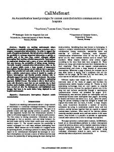
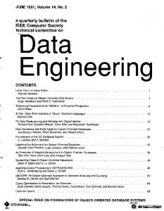
ECENT developments in computing device technologies are pushing devices to multi- and many-core architectures to exploit explicit parallelism rather than instruction-level parallelism. It has become more important to be able to fairly compare the disparate devices that enter the market, which incorporate both fixed and reconfigurable logic, both between and within respective architectural classifications. Performance and power metrics are needed to objectively compare devices in both high-performance computing (HPC) and embedded computing to understand device tradeoffs. These metrics will assist application scientists with algorithm-guided device selection early in the development cycle. A modern computational device, regardless of whether or not it is an HPC or accelerator device, has several key components that can be used to characterize the device. Fig. 1 shows how four key metrics are related in the characterization of a device for performance comparison. The first common component in this framework is the computational cores on the device. With the modern multiand many-core push, we are seeing an increasing number of cores on a device. These cores can take many shapes and sizes but in the end all work to perform the computations that the device uses to complete its tasks. The computational capacity of these cores can be used to compare differing devices if they are computing the same task. Computational density (CD) and its power-aware version, computational density per watt c 2010 IEEE 978-1-4244-9517-7/10/$26.00
Fig. 1.
Device Characterization Framework and Metrics
(CD/W) are metrics for comparing devices based on these computational units. Another major type of component typically found within a device is internal memory units. These can be distinguished because they are very close to the computational cores and are the lowest in the memory hierarchy. The bandwidth between these memory units and the computational cores will determine how many operations can be fed into the computational units and thus can be a limiting factor in performance. The internal memory bandwidth (IMB) metric is used to compare various devices based on how many operations can be sustained by the computational cores for a given application’s needs. The third major component found in modern computational devices starts to move data outside the device. Memory units inside the device are supplemented with external memory units. These units are not as close to the computational cores as the internal memory units, but they are typically much larger and hold application instructions and data ready to be quickly passed into the device for use. The bandwidth of these external memory units is a key metric for application performance. With an increasing number of cores being placed on a device, it has become far more important to keep them fed with data
as fast as possible. External memory bandwidth (EMB) is a metric that is very useful for quantifying this trait. The final major component that this paper addresses is the farthest line of communication from the computational cores, the input-output (I/O) ports. These ports allow information, usually data, to be passed from sensors, controls, or any other of a variety of sources into and out of the computational cores. These connections range from slow serial connections for debugging to high-speed serial and parallel communication standards. The ability of a device to keep acquiring and processing meaningful data is key to its ability to perform well in today’s environment. The input-output bandwidth (IOB) metric is a key metric for comparing devices in environments where large amounts of continuous data processing is required. IOB and the other metrics work together to help compare a set of disparate devices and allow device users to consider their needs in a device before spending significant resources into development. This paper extends our previous work [1] by introducing two new device metrics. In addition to the original set of metrics defined in [1] for computational density (CD), CD per watt (CD/W) and internal memory bandwidth (IMB), new metrics for off-chip bandwidth are introduced in this paper: external memory bandwidth (EMB) and I/O bandwidth (IOB). These metrics are used to characterize how well each device can interact with the rest of the system. In Section III, the original set of metrics is briefly reviewed and the new metrics are defined in more detail. This paper also extends our previous work by evaluating a set of new devices and new device categories (such as digital signal processors (DSPs) and NVIDIA’s Ion platform) based on the complete suite of device metrics (the previous metrics along with EMB and IOB). Results described in Section IV will show interesting outcomes in terms of computational density per watt and a trend of rapidly increasing I/O capabilities of devices. Section V provides a summary and conclusions. II. R ELATED W ORK This work evaluates the computational performance of the two major categories of processing devices: Fixed (FMC) and Reconfigurable (RMC) Multi- or Many-Core devices. Dehon [2] relates the number of processing elements, their width, and clock frequency to performance, normalized by die area and process technology. Dehon’s paper proposed a metric similar to the bit-level computational density we use in our work. Our previous work in Williams et al. [1] introduced CD, a metric which is used to determine the computational capability of a device and compare it to other devices, both within and between architectural categories at varying levels of precision such as floating-point, integer, and bit-level. Our work is a direct extension of these metrics by introducing newer bandwidth metrics and adding newer devices to perform a comprehensive evaluation. Bandwidth metrics form an important part of the device metrics which we introduce. Sohi and Franklin [3] illustrate
how low cache bandwidth hampers system performance especially when instruction issuing or parallel processing capabilities increase. Saulsbury et al. [4] suggest that integrating simple single-scalar processors tightly with memory can outperform high-end superscalar processors with traditional memory hierarchies and bandwidth limitations. Burger et al. [5] shows that memory bandwidth is a major performance bottleneck on many benchmarks due to latency-hiding techniques. The operand transfer rate from external memory and the effectiveness of on-chip memory in reusing operands are increasingly having a bigger impact on system performance. These works have helped to lay the groundwork for this expansion and extension of device metrics and have given a glimpse into the vast landscape of fair device characterization and comparison. In the next section, this paper reviews the specific methodologies used in the CD, CD/W, and IMB metrics and introduces new methodologies for our external extensions of these metrics. III. M ETHODOLOGY A. Review of CD and CD/W The CD metric [1] is used to determine the computational capability of a device and compare it to other devices, both within and between architectural categories at varying levels of precision. A device’s capability for computation is characterized by its integer CD, floating-point CD, and bit-level CD at various sizes. As in [1], we use MC to collectively refer to multicore and many-core devices, which have at least two major computational components in a single package; Fixed MC (FMC) and Reconfigurable MC (RMC) are the two primary classes. FMC devices have a fixed hardware structure that cannot be changed after fabrication. RMC devices can change their logical hardware structure after fabrication to adapt to changing problem requirements. The reader should refer to [1] for a more detailed discussion on the reconfigurability factors that are used to classify a device as either FMC or RMC. To determine the integer CD for FMC and coarse-grained RMC devices, Eq. 1 is used, where Ni is the number of integer execution units or the number of integer instructions that can be issued simultaneously of element type i, CP Ii is the average number of clock cycles per integer instruction for element type i (such as DSP, ALU, or LUT resources), and f is the operating frequency of the device. The subscript i represents the type of computational element within the device that is under analysis. The summation over i, in this equation, takes into account architectures that support vector/SIMD integer instructions by including different types of computational components. We assume that only addition and multiplication operations are considered, and the number of parallel operations is maximized while keeping the number of additions and multiplications equal. When calculating the number of parallel operations supported by a device, we consider a hardware-supported, multiply-accumulate operation as only one operation.
CDint = f ×
X Ni CP Ii i
(1)
For FPGAs, integer CD is determined using achievable frequency and the number of parallel operations of a fully utilized logic fabric and DSP resources. A single integer core for both addition and multiplication is instantiated on an FPGA using vendor IP cores. For each core, the resource utilization along with the maximum achievable frequency is determined from the vendor tools. This information allows the number of simultaneous cores that can be instantiated on a device to be determined, utilizing all available DSP and logic resources and assuming 15% logic overhead for steering logic and I/O interfacing. Again, only addition and multiplication operations are considered and balanced. The number of parallel operations is multiplied by the maximum achievable frequency, limited by the lowest between multiplication and addition. Based on the amount of available on-chip memory resources, the number of parallel operations is limited in order to incorporate memory bandwidth or on-chip RAM resources for data buffering, which can have a limiting effect on the peak CD. The on-chip memory needs to allocate two operands per operation for memory-sustainable CD, which is the CD used throughout this paper. This provision ensures that the number of parallel operations a device can support is limited by the realistic ability of the internal memory structure to provide data for each parallel operation. To illustrate the process in which CD is calculated for a device, a Virtex-6 SX475T FPGA can be analyzed for integer performance. For example, when calculating the 32-bit integer (i.e. Int32) CD for the Virtex-6 SX475T, the Int32 IP cores of adders and multipliers are first generated with tools supplied by the vendor. One of each design is synthesized and simulated on the FPGA. Using the utilization report, it can be determined that the fabric could support 1937 operations in parallel, half multiplies and half additions. From [6] we see that the block RAMs of the fabric can only supply 1064 pairs of operands each clock cycle. Since this amount is less than the maximum number of parallel operations, 1064 is the maximum amount of memory-sustainable operations that can be computed in parallel. Using the timing report generated from the design of multipliers and adders, the operating frequency is determined to be 296 MHz. Since each operation takes one cycle, CPI is 1, and we are computing 1064 operations in parallel. Using Eq. 1, the memory-sustainable Int32 CD for the device is calculated as: CDint = 296 MHz × 1064 ops = 314.944 GOPS
(2)
The CD per watt (CD/W) metric is calculated by taking the CD for each level of parallelism and dividing by the power consumption at that level of parallelism. For FMC, the maximum power is used. For RMC, power is assumed to scale linearly with resource utilization and achievable frequency. Floating-point CD and CD/W are determined using a similar procedure as integer CD and CD/W. For a more detailed methodology of CD and CD/W, please refer to [1] [7] [8].
B. Review of IMB IMB is used to measure the on-chip memory interface capabilities. It quantifies the memory performance of a system by measuring the rate at which data can be transferred from onchip memories to the processing elements. IMB is important because memory often becomes a bottleneck, limiting the amount of operands supplied to the processing elements of the system. It is defined separately for cache-based systems (CBS) and block-based systems (BBS). Eq. 3 from [1] is used to calculate the IMB for BBS. IM Bblock =
X N i × Pi × W i × f i i
8 × CP Ai
(3)
In Eq. 3, Ni is the amount of block memories of type i, Wi is the data width, Pi is the amount of ports for memory of type i, CP Ai is the number of cycles per access to memory, division by 8 is to convert from bits per second to bytes per second, and fi is the frequency of the device, or if the frequency is not constant, as in FPGAs, then it is variable up to the operating frequency of the design. Once again, the subscript i denotes memory type to support devices that have more than one type of internal memory. In CBS, multiple separate levels of cache may exist, and IMB is calculated separately for each, so that the hit-rate consideration is only included per level of cache. They also feature hardware to determine associativity, line size, coherency protocol, replacement algorithms, etc. These parameters affect the access times of the cache, and are addressed by the frequency and cycles per access variables. The equation used to calculate IMB for CBS is given from [1] as follows: IM Bcache = % hitrate ×
X Ni × Pi × Wi × fi i
8 × CP Ai
(4)
In Eq. 4, Ni is the number of block memories of type i, Wi is the data width, Pi is the number of ports for memory of type i, CP Ai is the number of cycles per access to memory, division by 8 is to convert from bits to bytes per second, and fi is the frequency of the device. IMB does not account for register access times; instead it is assumed that these are internal components separate from block or cache memory. Registers are usually quickly accessed and do not hinder performance. IMB only seeks to evaluate the rate at which processing elements have all the necessary operands, and it is assumed that registers do not limit this rate. To aid the understanding of this calculation, an example using the Virtex-6 SX475T is presented. On the Virtex-6 SX475T, there are 1064 36Kb block RAMs. Each of these has a 72-bit port width, and simple dual-port functionality. The maximum operating frequency is used, which is 600 MHz. Since all of these BRAMs are the same, the summation is over this single set. Using Eq. 3, the IMB for the device is calculated as: IM Bblock =
1064 × 2 × 72 × 600 MHz = 7776 GB/s (5) 8×1
C. EMB EMB is proposed and introduced in this paper to describe the total bandwidth achievable to external memory from a device or vice-versa. EMB only includes the bandwidth of usable data, so extra bits used for error-correction coding (ECC) are not included. EMB and IOB (detailed in Section III-D), are introduced to characterize the capability of a device to interface with the rest of the system. EMB does not include I/O bandwidth or network-controller bandwidth as these are typically at the cost of a user-defined interfacing implementation for an application. EMB is defined only for directly attached memory. Although a device could access another device’s memory through an I/O port, this is not considered in the calculation of EMB. For FMC and coarse-grained RMC devices with built-in memory controllers, EMB is the sum of the concurrent EMB provided by all memory controllers. For devices that use a front-side bus (FSB), the entire bus is allocated for memory bandwidth. Otherwise, the external datapath width and the switching frequency are used to determine EMB. To determine EMB for FPGAs, the methodology employed is similar to determining CD for FPGAs. A single memory controller is instantiated on the FPGA using a vendor IP core. The resource utilization is determined along with the maximum-achievable memory interface frequency. The number of simultaneous cores that can be instantiated utilizing all available resources are determined, assuming 15% logic overhead for steering logic and I/O interfacing. Limiting factors include the number of LUTs, ALMs/Slices, and the number of bonded IOBs. To get a better understanding of how to calculate EMB, a step by step calculation for Virtex-6 SX475T is as follows. A single DDR2 memory-controller IP core is instantiated on the chip and the resource utilization is obtained. The maximum number of DDR2 controllers that can be instantiated simultaneously is calculated by dividing the available number of bonded IOBs (840) by the number of IOBs used (121) by a single memory controller. The memory-interface frequency (533 MHz) is multiplied with the memory-interface width (64 bits) using the appropriate units, to get the EMB of one DDR2 controller as 8.528 GB/s. This rate is in-turn multiplied by 6, the maximum number of DDR2 controllers instantiated to calculate a maximum EMB of 51.168 GB/s. D. IOB IOB is proposed here and used to describe the total I/O capabilities of a device, not just the external memory bandwidth. Devices with dedicated ports for interfacing with memory often also have additional ports for data input/output, which are not considered in the EMB calculation. Devices may also have higher bandwidth capabilities on a port that shares all or some pins with ones used for a memory interface, such as is the case for FPGAs. An I/O bandwidth metric describes the maximum data throughput of a device that EMB omits or a higher total bandwidth that is possible on a device. IOB is calculated as the total aggregate sum of the bandwidth provided by all inputs and outputs that can operate
concurrently. The highest bandwidth ports are used when there is overlap or non-concurrency. Eq. 6 shows the aggregation of I/O ports based on i, where i represents the different types of I/O ports that can be used concurrently. Line encoders can be used to encode data into a different format which benefits transmission for reasons other than data throughput. Various schemes such as 8b/10b or 64b/66b, can be employed that have varying overheads on the line rate. If an encoding scheme is used, such as 8b/10b, then αi represents the fraction of IOB that is available for data. For the case of 8b/10b encoding, we assume that fraction is 0.80. The aggregate sum is then added to the input/output bandwidth of any dedicated external memory controllers available on the device (denoted as IOBmem ). X IOB = IOBmem + αi × IOBi (6) i
There are numerous ways to characterize the I/O of a device. In single-ended I/O, one signal is made between two ICs and compared to a specified voltage range or to a reference voltage. In differential signaling, two signals are made between two ICs and the signals are compared to each other to determine the logic value [9]. These two signaling methods can have differing bandwidths, even when comparing two single-ended signals to a single differential signaling pair. When studying devices’ IOB, it is important to use fair comparisons and keep all parameters equal when direct comparisons are desired. For an example, consider the Nvidia Tesla C1060 GPU. There are two interfaces for IO on this processor, the memory interface and the PCIe bus. To compute IOB, the aggregate is taken of both interfaces and the calculations are shown in Eqs. 7-9. It has 4 GB of dedicated GDDR3 memory clocked at 800 MHz on a 512-bit interface. The PCIe interface has a 500 MB/s transfer rate for each lane in each direction. IOBmem = 800 MHz × (512 bits/8) × 2 = 102.4 GB/s (7) IOBP CIe = 500 MB/s × 16 Lanes × 2 = 16 GB/s IOB = IOBmem + 1 × IOBP CIe = 118.4 GB/s
(8) (9)
IV. R ESULTS AND A NALYSIS In this section we focus on reporting trends observed amongst various devices when the suite of metrics is applied to them. For our study, a full range of results were collected, including Bit, Int16, Int32, Single-Precision Floating Point (SPFP) and Double-Precision Floating Point (DPFP) forms of CD and CD/W, as well as IMB, EMB, and IOB for the devices shown in the following figures. Due to the large number of devices which have been included in our study, we illustrate the more interesting cases through graphs in this section and have reported all the other metrics in expansive tables in the Appendix. Many of these devices are new to this paper and were not included in [1]. Only selected metrics are presented in detail: Int16 CD/W for RMC and FMC devices; SPFP CD/W for RMC and FMC devices; EMB for FMC and RMC devices; and IOB for FMC and RMC devices.
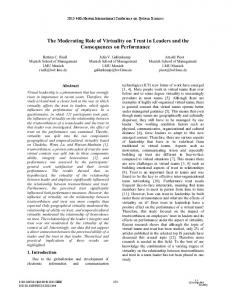
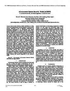
The FMC devices highlighted in this study, listed in Fig. 3, include a range of CPUs, DSPs, and GPUs. The RMC devices, listed in Fig. 2, include FPGAs of varying types, the Tilera TILE64 processor, and the PACT XPP-3c. In this study the maximum level of exploitable parallelism of devices was calculated and the performance of devices is compared by varying the level of parallelism. This means that the clock frequency is recalculated for each metric (i.e. Int16 vs Int32) and varies based on which metric is being calculated. A. CD and CD/W Metrics Fig. 2 shows Int16 and SPFP forms of CD/W for RMC devices. The bars are grouped by device, one representing Int16 precision and the other SPFP. The data labels above each bar denote the maximum number of parallel operations that each device is capable of sustaining at the given precision. Some interesting results can be observed from the figure. The EP4SE530 has the highest memory-sustainable Int16 CD/W (54.07 GOPS/Watt) due to the large logic fabric and the high amount of on-chip memory. The Virtex-6 LX760 has the highest memory-sustainable SPFP CD/W (10.27 GOPS/Watt). The PACT XPP-3c has the largest number of parallel operations (348) of non-FPGA devices studied and has higher Int16 CD/W (16.24 GOPS/Watt) than all the other coarse-grained RMC devices such as the TILE64 even though it has no SPFP support.
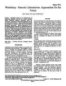
have high power consumption which offsets the benefits of its superior SPFP performance. For high levels of parallelism, the GeForce GTX480 has the highest SPFP CD/W (4.12 GOPS/Watt) of the FMC devices studied. Although highend FPGAs in the Stratix IV and Virtex-6 families have a much larger number of parallel operations than the GeForce GTX480, the achievable frequency is low compared to the operating frequency of the GTX480. However, the FPGAs mentioned have a CD/W that is 3x larger than the GTX480. Interestingly, the GTX285 does not perform nearly as well as the GTX480 even though they are of the same family due to the high power consumption of the device and lower number of processors. Similarly, the Core i7-980X (1.84 GOPS/Watt) and Itanium 9350 (1.18 GOPS/Watt) have high CD performance, but are not power-efficient. The TI OMAP-L137 DSP uses very low power which allows it to perform well in CD/W, despite it having the lowest CD of the devices studied. For a complete list of devices with their respective CD values, see Table V in the Appendix. Table II in the Appendix, reports CD for FPGA devices for Int16 and Int32 precisions. This table is included to point out the difference in frequencies and power usage over various precisions for FPGAs.
Fig. 3. Fig. 2.
CD/W for FMC devices
CD/W for RMC devices
Fig. 3 shows Int16 and SPFP forms of CD/W for FMC devices in the same format as Fig. 2. The TI-OMAP device has the highest Int16 CD/W ratio (7.72 GOPS/Watt). Even though this device does not have a large number of computational resources, it achieves high CD/W due to its low power consumption. Another trend visible from this figure is significantly lower CD/W numbers for the FMC devices as compared to RMC which can be directly attributed to the presence of a vast number of computational resources on a FPGA and the higher power consumption of FMC devices. The Virtex-6 LX760 has the greatest unconstrained Int16 CD (3443.2 GOPS), but it is limited by its IMB, which significantly lowers the memorysustainable CD/W to 48.37 GOPS/Watt. For SPFP CD/W, the results show that most RMC devices perform better than GPU devices; this is because GPU devices
B. EMB Results Fig. 4 shows EMB for key RMC devices in GB/s. The Virtex-6 LX760 has the highest EMB (68.2 GB/s) of the devices studied due to the fact that the LX760 has a higher number of bonded IOBs than corresponding devices. These bonded IOBs allow the simultaneous instantiation of a higher number of DDR2 controllers resulting in a higher EMB. The numbers above each bar in the graph show the remaining logic utilization after the instantiation of memory controllers required to attain maximum EMB. These percentages illustrate the fact that a very low logic overhead is required to have multiple memory controllers and hence attain a higher EMB. Interestingly it is seen that most of the devices require almost no logic utilization after instantiating their memory controllers
whereas the Virtex-4 SX55 occupies almost 40 % of the chip for its two memory controllers.
Fig. 4.
EMB for FPGA Devices
Fig. 5 shows EMB for FMC devices in GB/s. As expected, GPU devices perform the best amongst all categories of devices. GPUs are designed to handle highly parallel applications which require large sets of streaming data. This design makes it necessary to have fast and wide memory buses that result in high EMB. The Nvidia GeForce GTX480 has the highest EMB (177.4 GB/s) amongst all devices. CPU devices typically handle smaller applications using smaller sets of data, hence they have a lesser EMB. The Intel Xeon X7560 has the highest EMB (34.11 GB/s) amongst the non-GPU FMC devices, which is due to the addition of the high-bandwidth Intel Quick Path Interconnect (QPI).
Fig. 5.
EMB for FMC Devices
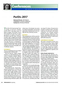
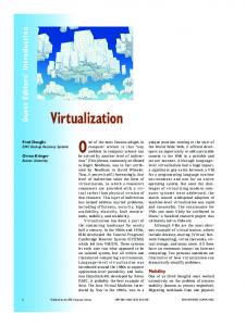
C. IOB Results Fig. 6 shows IOB for both FMC and RMC devices in GB/s. The package of an FPGA is shown in parenthesis. The FPGAs
assume differential signaling and an 8b/10b encoding scheme, which has an overhead of 20 percent, in order to compare the I/O data rates of FMC devices to the I/O line rates of the FPGAs. The I/O bandwidth shown consists of equal parts input and output. It should be noted that an unbalanced I/O can have an effect on the total I/O achievable by a device since not all channels are bidirectional and there may be an unequal number of input and output ports. The GeForce GTX 480 has the highest IOB (193.4 GB/s) of the devices studied, followed by the GTX 285 (175 GB/s). GPUs are optimized for 3D rendering, which requires processing on large working sets of data. This form of data processing makes having a wide and fast memory bus a necessity to achieve high performance. Comparing against microprocessors, the amount of data that needs to be processed is too large to fit in the cache of a CPU. The working set of applications that typically run on CPUs have random memory access patterns and are smaller than those that run on a GPU, requiring many frequent fetches from off-chip memory. CPU memory interfaces are shifting from buses to a very fast group of serial data lines communicating via packets with much lower latency, such as HyperTransport or Intel’s QPI. As CPUs have been increasing in the number of cores and IOB, streaming applications may be more effectively parallelized on them. V. C ONCLUSIONS We have enhanced our existing methodology for device metrics to assess the off-chip memory bandwidth of devices, using external memory bandwidth (EMB) and I/O bandwidth (IOB). Developers can use the device metrics described in this paper and in [1] to assist in algorithm-guided device selection early in the development cycle and to understand device tradeoffs. We have also presented a study of a new and diverse set of devices to determine their computational capabilities and off-chip bandwidths. There is a large variation in the resulting data that arises when these metrics are used to study disparate accelerator technologies. A few interesting trends observed by evaluating the data include FPGA devices showing the highest CD and CD/W for bit and integer operations. This trend can be attributed to the large fabrics and amount of LUTs enabling FPGAs to achieve massive amounts of parallelism. As observed in Section IV, GPUs tend to perform well in most categories; however, they stand out in floating-point calculations due to the high clock rates of their shader units and the sheer number of them (GTX480 has the highest SPFP CD: 1031.136 GOPS). CPUs also perform well in floating-point, especially doubleprecision. Many of the other devices have to expend extra resources or clock cycles for DPFP calculations, however modern CPUs have dedicated functional units for that purpose. Combined with the highest clock speeds of any of the studied devices, they perform DPFP operations well. The EMB and IOB results show that GPUs have the highest external bandwidth, with very wide memory controllers working at very high frequencies. FPGAs also perform well,
Fig. 6.
IOB data for selected devices
but their operating frequency keeps them from matching GPU memory bandwidth. Some of the newer CPUs, particularly the Intel Core i7-980x, achieve very high IOB scores as compared to other CPUs. This is due to the shift from the FSB connection to QPI. Using a point-to-point interconnect allows a much higher clock rate than a shared bus, providing much higher data bandwidth. Future work is planned to allow for more user defined parameters when calculating certain metrics. These parameters include the addition of more avalible operations and varying the ratio of operations when determining CD. This expansion will allow users to more closely determine which device would fit their algorithm based upon the required calculations. Another planned extension of these metrics includes the parameterization of IOB and EMB metrics. Our goal is to allow users to define and customize the individual attributes used to calculate each metric to best suit their application. VI. ACKNOWLEDGMENTS This work was supported in part by the I/UCRC Program of the National Science Foundation under Grant No. EEC0642422. The authors gratefully acknowledge vendor equipment and/or tools provided by various vendors that helped make this work possible.
R EFERENCES [1] J. Williams, A. George, J. Richardson, K. Gosrani, C. Massie, and H. Lam, “Characterization of fixed and reconfigurable multi-core devices for application acceleration,” ACM Transactions on Reconfigurable Technology and Systems (TRETS), vol. 3, no. 4, 2011. [2] A. DeHon, “Reconfigurable architectures for general-purpose computing,” Massachusetts Institute of Technology, Cambridge, MA, USA, Tech. Rep., 1996. [3] G. S. Sohi and M. Franklin, “High-bandwidth data memory systems for superscalar processors,” SIGOPS Operating Systems Review, vol. 25, no. Special Issue, pp. 53–62, 1991. [4] A. Saulsbury, F. Pong, and A. Nowatzyk, “Missing the memory wall: the case for processor/memory integration,” in ISCA ’96: Proceedings of the 23rd Annual International Symposium on Computer Architecture. New York, NY, USA: ACM, 1996, pp. 90–101. [5] D. Burger, J. R. Goodman, and A. K¨agi, “Memory bandwidth limitations of future microprocessors,” in ISCA ’96: Proceedings of the 23rd Annual International Symposium on Computer Architecture. New York, NY, USA: ACM, 1996, pp. 78–89. [6] Virtex-6 Family Overview, Xilinx, Inc., 2008. [7] J. Williams, A. George, J. Richardson, K. Gosrani, and S. Suresh, “Computational density of fixed and reconfigurable multi-core devices for application acceleration,” Proc. of Reconfigurable Systems Summer Institute 2008 (RSSI), July 7-10, 2008. [8] ——, “Fixed and reconfigurable multi-core device characterization for hpec,” Proc. of High-Performance Embedded Computing Workshop (HPEC), Sep. 23-25, 2008. [9] A. Athavale and C. Christensen, High-Speed Serial I/O Made Simple, A Designers’ Guide, with FPGA Applications, Xilinx Connectivity Solutions, April 2005.
VII. A PPENDIX : A DDITIONAL DATA TABLE I EMB OF NON -FPGA DEVICES
TABLE II CD OF FPGA DEVICES SHOWING FREQUENCY AND POWER VARIATIONS
TABLE III IMB FOR BBS OVER A RANGE OF ACHIEVABLE FREQUENCIES (GB/ S )
TABLE IV IMB FOR CBS FOR VARIOUS HIT RATES (GB/ S )
TABLE V M EMORY- SUSTAINABLE CD ACROSS PRECISIONS