Int. J. Electrochem. Sci., 5 (2010) 509 - 516 International Journal of
ELECTROCHEMICAL SCIENCE www.electrochemsci.org
Computational Approach to Investigation of Template/Monomer Complex in Imprinted Polymers; Dinitrobenzene Sensor S. Riahi1,2,*, S. Eynollahi2,M.R. Ganjali2,3and P. Norouzi2,3 1
Institute of Petroleum Engineering, Faculty of Engineering, University of Tehran, Tehran, Iran Center of Excellence in Electrochemistry, Faculty of Chemistry, University of Tehran, P. O. Box 14155-6455, Tehran, Iran 3 Endocrinology & Metabolism Research Center, Tehran University of Medical Sciences, Tehran, Iran * E-mail:
[email protected] 2
Received: 2 April 2010 / Accepted: 15 April 2010 / Published: 30 april 2010
In this research a computational approach was applied to screening the mechanism of imprinting polymers. Semi-empirical PM3 and HF/6-31G methods were carried out for molecules optimization and calculation of intra molecular interaction. MAA (Methacrylic acid), the most commonly used functional monomer was chosen as functional monomer and EGDMA (Etylen glycol dimetacrilic acid) was chosen as cross linker for Dinitrobenzene (DNB) imprinting polymer. It was found that 1:4 ratios of template: functional monomers were the most stable conformation.
Keywords: Computational approach, Imprinted polymer, Chemometrics, Interaction energy, HF
1. INTRODUCTION Molecular imprinting is a new technique that produces synthetic receptors that preferentially bind with a particular molecule (template). The principle of molecular imprinting is based on copolymerization of functional monomers and cross-linkers in the presence of template (1-2). In this way, complementary groups situate behind them. The polymers are synthesized using this method are called “artificial receptors”. These receptors show high selectivity towards template molecules. Also, these receptors are used in solid phase extraction (SPE), electrochemistry, drug delivery and high liquid chromatography (HPLC) because of its high selectivity (3-6). For evaluation of the selectivity of MIP, absorption of a molecule that is similar to the template molecule in structure, called pseudo template is measured. In this work, Dinitrobenzene was selected as template and TNT as pseudo template.
Int. J. Electrochem. Sci., Vol. 5, 2010
510
The affinity and selectivity of imprinting polymer basically depend on the parameters which are determined by the strength and type of intermolecular interactions. Therefore the knowledge of the type and orientations of involved functional monomers is crucial for imprinting polymers. Molecular simulation techniques play important roles in understanding and imagination of molecular level manners. These methods are powerful in calculating intra molecular energy and atomic charges in different phases. Molecular simulation softwares are able to depict a three dimensional picture from molecules that help us understand and imagine molecule configurations. Compared with experimental methods, computational approaches have advantages such as: low costs, less time consuming, safe for the human body (many solvents are cancerogen) and safe for the environment - no exposed chemicals. These methods maybe successfully applied in rational design and solvent prediction in imprinting polymer. There are several ways to compute and evaluate interaction energy between functional monomers and templates. In recent MIP researches, functional monomers and solvents were initially selected and then experimental were performed. In most cases computational methods such as DFT and HF methods were used (13-21). In grate molecules because of ab initio methods are time consuming, MD (molecular dynamics), MM (molecular mechanics) and semi empirical methods were used (21-28). In macro molecules simulation, only MM, MDNVT methods (mole, volume, temperature) and MDNPT (mole, volume, pressure, temperature) were used (29-31). In all these approaches, the main goal is to find the interaction energy between monomer(s) and template. This energy is the measure of monomer-template stability. Since only ab initio methods are reliable in the description of hydrogen bonding systems, we used HF/6-31G method in the calculation of interaction energy between DNB and MAA. In imprinting polymers, the commonly template/monomer ratio are 1/n (n≤), thus we have designed different configuration of template/monomers complexes for each ratio. Depend on binding energy, high binding energy corresponding to high stability. The most stable configuration consider as real station.
2. COMPUTATIONAL DETAILS In recent years the DFT method was applied in different branches of chemistry [7-31]. The experimental results were reported in Ref. [32]. Molecular structures of DNB, MAA and TNT were created with the HYPERCHEM software. The optimized molecular geometries were obtained through AM1 semi-empirical calculations and the Eigenvector Following method included in HYPERCHEM. Conformational analysis was carried out to localize the global minimum of each molecule. Frequency calculations were performed to confirm the nature of the stationary points. Vibrational frequencies were unscaled. Then, these optimized molecular geometries have been optimized using HF/6-31G methods in Gaussian 98. The optimized configuration of DNB, MAA are shown in Figure 1 and geometrical parameters are shown in tables 1 and 2.
Int. J. Electrochem. Sci., Vol. 5, 2010
511
Table 1. Significant computed geometrical parameters for DNB before and after complex formation DNB dihedrals D(6,1,2,3) D(6,1,2,9) D(13,1,2,3) D(2,1,6,5) D(2,1,6,7) D(13,1,6,5) D(1,2,3,4) D(1,2,3,14) D(9,2,3,4) D(4,5,6,1) D(4,5,6,7) D(16,5,6,1)
0.0 180.0 180.0 0.0 180.0 180.0 0.0 180.0 180.0 0.0 180.0 180.0
After interacting MAA -0.376 178.768 -179.355 -0.1333 -179.934 178.849 0.434 179.591 -178.711 0.582 -179.616 -179.830
DNB dihedrals
Before interacting MAA 1.398 1.398 1.105 1.400 1.505 1.389 1.100 1.389
After interacting MAA 1.398 1.396 1.106 1.400 1.495 1.389 1.102 1.389
Before interacting MAA 119.605 120.196 120.197 120.138 120.019 119.842 119.758 120.730 119.512 120.602 119.697 119.699
After interacting MAA 119.296 120.529 120.166 120.390 119.892 119.711 119.605 120.703 119.686 120.668 119.686 119.645
R(1,2) R(1,6) R(1,13) R(2,3) R(2,9) R(3,4) R(3,14) R(4,5) DNB dihedrals A(2,1,6) A(2,1,13) A(6,1,13) A(1,2,3) A(1,2,9) A(3,2,9) A(2,3,4) A(2,3,14) A(4,3,14) A(3,4,5) A(3,4,15) A(5,4,15)
Before interacting MAA
DNB dihedrals
D(1,2,9,11) D(3,2,9,10) D(2,3,4,5) D(2,3,4,15) D(14,3,4,5) D(3,4,5,6) D(3,4,5,16) D(15,4,5,6) D(1,2,9,10) D(1,6,7,8) D(1,6,7,12) D(5,6,7,8) DNB dihedrals
R(4,15) R(5,6) R(5,16) R(6,7) R(7,8) R(7,12) R(9,10) R(9,11) DNB dihedrals
A(4,5,16) A(6,5,16) A(1,6,5) A(1,6,7) A(5,6,7) A(6,7,8) A(6,7,12) A(8,7,12) A(2,9,10) A(2,9,11) A(10,9,11) A(4,5,6)
Before interacting MAA 180.0 180.0 0.0 180.0 180.0 0.0 180.0 180.0 0.0 0.0 180.0 180.0
After interacting MAA 148.209 147.997 0.020 179.807 -179.144 -0.525 179.882 179.687 -31.153 -34.230 147.715 145.967
Before interacting MAA 1.096 1.400 1.100 1.505 1.212 1.213 1.212 1.213
After interacting MAA 1.096 1.399 1.102 1.499 1.215 1.213 1.216 1.214
Before interacting MAA 119.509 120.731 120.136 120.019 119.844 119.189 118.916 121.893 119.189 118.917 121.892 119.759
After interacting MAA 119.617 120.769 120.424 119.814 119.760 119.036 119.538 121.395 119.291 119.695 121.010 119.611
Int. J. Electrochem. Sci., Vol. 5, 2010
512
-0.591(-0.611)
-0.584(-0.602)
1.309(1.336) -0.430(-0.407)
0.162(0.150)
0.138(0.146)
0.080(0.087)
0.046(0.044)
-0.430(-0.427) -0.591(-0.617)
-0.143(-0.139) 0.123(1.325) -0.584(-0.600)
0.046(0.045)
0.127(0.124)
0.138(0.142)
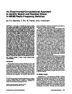
Figure 1. The optimized structure and the atomic charges of DNB before and after complexation Table 2. Significant computed geometrical parameters for MAA before and after complex formation EGDMA dihedrals D(3,1,2,4) D(3,1,2,8) D(7,1,2,4) D(2,1,3,9) D(2,1,3,10) D(7,1,3,9) D(1,2,4,5) D(1,2,4,6) D(8,2,4,5) D(2,4,6,12) D(2,4,6,13) D(5,4,6,12) EGDMA bond lengs R(1,2) R(1,3) R(1,7) R(2,4) R(2,8) R(3,9) R(3,10) R(3,11) R(4,5) R(4,6) R(6,12) R(6,13)
Before interacting DNB 179.696 0.459 -0.205 121.155 -120.294 -58.938 -4.955 178.995 174.306 -164.827 -31.775 18.797
After interacting DNB 179.711 0.336 -0.167 121.144 -120.296 -58.972 0.830 -175.102 -179.775 -165.421 -30.526 18.319
EGDMA angels
A(2,1,3) A(2,1,7) A(3,1,7) A(1,2,4) A(1,2,8) A(4,2,8) A(1,3,9) A(1,3,10) A(1,3,11) A(9,3,10) A(9,3,11) A(10,3,11) A(2,4,5) Before After interacting A(5,4,6) interacting DNB DNB 1.336 1.337 A(5,4,6) 1.478 1.478 A(4,6,12) 1.099 1.099 A(4,6,13) 1.479 1.479 A(12,6,13) 1.098 1.098 1.098 1.098 1.098 1.098 1.098 1.098 1.225 1.229 1.421 1.414 0.995 0.998 0.994 0.994
Before interacting DNB 122.861 120.812 116.326 121.795 120.779 117.420 110.356 110.235 113.291 107.464 107.654 107.620 125.343 117.224
After interacting DNB 122.843 120.844 116.312 121.882 120.721 117.393 110.334 110.249 113.291 107.475 107.645 107.626 125.053 117.124
117.224 115.251 114.271 112.798
117.124 115.845 114.752 113.223
Int. J. Electrochem. Sci., Vol. 5, 2010
513
According to Mulliken charges and common chemical properties, possible configurations of 1/n DNB/MAA complex molecular systems were designed and optimized using PM3 semi-empirical method and interaction energies (∆E) were calculated from following equation: ∆E=E (template–monomer complex) − [E (template) + nE (monomer)] “n” refers to the number of monomers in the template-monomer complex. For a given complex, the higher values of ∆E indicate high binding energy and the most stable conformation. The most stable conformation was selected as its ratio conformation. Then, the interaction energies were calculated with HF/6-31G using Gaussian 98. Interaction energies are reported in Table 3. According this table, it was found that the 1/4 template-monomer ratios, the most stable in DNB imprinting polymer.
0.113(0.119)
0.043(0.049)
0.046(0.048)
-0.005(0.009)
-0.095(-0.093) 0.054(0.055)
-0.227(-0.219) 0.059(0.069)
0.056(0.054)
0.257(0.273) -0.038(-0.044)
0.116(0.103)
-0.378(-0.413)
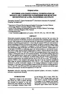
Figure 2. The optimized structure and atomic charges of MAA before and after complexation
Table 3. Interaction energies for 1/2 to 1/5 template-monomer ratios Number of functional monomers 1 2 3 4 5
Interaction energy -1.83 -3.5 -5.8 -12 -6.3
3. IMPRINTED POLYMER DESIGN FOR DNB The optimized structure of the complex of DNB and MAA are shown in Figure 3. The equilibrium geometries of the complex subsystem were determined and confirmed by subsequent calculations of the vibrational frequencies. The geometrical optimizations were performed using the HF method and the significant computed geometrical parameters are available in Table 1. This table contains some significant geometrical values including: bond lengths, bond angles and dihedral angles.
Int. J. Electrochem. Sci., Vol. 5, 2010
514
Figure 3. The optimized structures of the complex of MAA and DNB . 4. ANALYSIS OF MULLIKEN CHARGES Results for charges in the following cases (Figures 1,2) were studied to illustrate the mechanism of template absorption in the polymer cavity: 1) 2) 3) 4)
Charges of polymers in the unoccupied polymer Charges of polymers in the occupied polymer with template Charges of polymers in the occupied polymer with pseudo template Charges of the template and pseudo template in free stations, and to replace those in the polymer cavity
Overall, in order to illustrate the cross linker role in imprinting, the most stable arrangement of template with MMA that is similar to the cross linker was designed and interaction energies were calculated. In this complex the role of MMA is a functional monomer. Charge distributions of polymers have three categories: polymer, polymer-template and polymer-pseudo-template, which essentially show no considerable difference between one another. In the other words, charge distribution in the above three categories are approximately equal. In the case of DNB and TNT, they are both very different in charge distribution in the free molecule and in the molecule that replaces the polymer cavity. The outer atom charges are adopted in a manner that electrostatic attractions are maximized. From this we conclude that if a great molecule is replaced or
Int. J. Electrochem. Sci., Vol. 5, 2010
515
induced in solution, there are many different charge distributions on its surface. Small molecules could be replaced behind it and adopted towards the grate molecule and the total systems are stablest compare with two single atoms and adsorption occurs.
5. CONCLUSIONS In this research it was found that 1/4 template monomer ratio is the most configuration. Interaction energies between polymer-template is (-12. 6) KCal/Mol, and that between the polymerpseudo-template is (-8.7) KCal/Mol. These results indicate the selectivity of the polymer towards DNB and TNT. These results were also obtained in the experimental setting but at a lower degree. Failure of this depends on several reasons such as; high similarity between two molecules, similarity in type and position of functional groups in two molecules, disability in simulation of solution matrices etc. Nevertheless the designing of this polymer has some advancement over other automatic polymerization software such as; inducing the cross linker, variability in density of polymers depending on experimental solution temperature and concentration, cavity design on the polymer, and last but not least it illustrates some molecular manners and mechanisms such as adsorption. Acknowledgements We gratefully acknowledge the support of this work by the Institute of Petroleum Engineering, Tehran University Research Councils.
References 1. Molecular Imprinting. By M. Komiyama, T. Takeuchi, T. Mukawa, and H. Asanuma Copyright© 2003 Wiley-VCH Verlag GmbH & Co. KGaA 2. M.J.Whitcombe, E.N. Vulfson, Imprinted polymers. Adv. Mater. 13 (2001) 467. 3. N. Masqué, R. M. Marcé and F. Borrull. TrAC Trends in Analytical Chemistry, 20 (2001) 477. 4. Derek Stevenson, TrAC Trends in Analytical Chemistry, 18 (1999) 154. 5. Wonbae Lee, Masahiko Hara and Haiwon Lee. Materials Science and Engineering:C 24 (2004) 315. 6. S. Riahi, M. R.Ganjali, E. Pourbasheer, F. Divsar, P. Norouzi, M. Chaloosi, Current Pharmaceutical Analysis, 4 (2008) 231. 7. S. Riahi, A. B. Moghaddam, M. R. Ganjali, P. Norouzi and M. Latifi, J. Theor. Comput. Chem. (JTCC), 6 (2007) 255. 8. S. Riahi, P. Norouzi, A. B. Moghaddam, M. R. Ganjali, G. R. Karimipour and H. Sharghi, Chem. Phys. 337 (2007) 33. 9. S. Riahi, A. B. Moghaddam, M. R. Ganjali and P. Norouzi, J. Mol. Struct. (THEOCHEM), 814 (2007) 131. 10. M. R. Ganjali, T. Razavi, F. Faridbod, S. Riahi, P. Norouzi, Current Pharmaceutical Analysis, 5 (2009), 28. 11. S. Riahi, M. R. Ganjali, P. Norouzi and F. Jafari, Sens. Actuators B, 132 (2008) 13. 12. [Online] available: http://www2.netdoctor.co.uk/medicines/100001882.html 13. S. Riahi, A. Beheshti, M. R. Ganjali and P. Norouzi, Spectrochim. Acta Part A, 74 (2009) 1077.
Int. J. Electrochem. Sci., Vol. 5, 2010
516
14. M. R. Ganjali, A. Alipour, S. Riahi, B. Larijani and P. Norouzi, Int. J. Electrochem. Sci., 4 (2009) 1262. 15. S. Riahi, M. R. Ganjali, A. B. Moghaddam, P. Norouzi and M. Niasari, J. Mol. Struct. (THEOCHEM), 774 (2006) 107. 16. S. Riahi, M. R. Ganjali, A. B. Moghaddam, P. Norouzi and M. Latifi, J. Mol. Struct. (THEOCHEM), 807 (2007) 137. 17. S. Riahi, M. R. Ganjali, A. B. Moghaddam and P. Norouzi, J. Theor. Comput. Chem., 6 (2007) 331. 18. S. Riahi, M. R. Ganjali, A. B. Moghaddam and P. Norouzi, J. Theor. Comput. Chem., 6 (2007) 255. 19. S. Riahi, F. Jalali Farahani, M. R. Ganjali, A. B. Moghaddam and P. Norouzi, J. Mol. Struct. (THEOCHEM), 850 (2008) 48. 20. S. Riahi, M. R. Ganjali, A. B. Moghaddam, P. Norouzi, J. Mol. Model., 14 (2008) 325. 21. F. Faridbod, M. R. Ganjali, R. Dinarvand, S. Riahi, P. Norouzi, Journal of Food and Drug Analysis, 17 (2009) 264. 22. S. Riahi, M. R. Ganjali and P. Norouzi, J. Theor. Comput. Chem., 7 (2008) 317. 23. S. Riahi, M. R. Ganjali, A. B. Moghaddam and P. Norouzi, Spectrochim. Acta A, 71 (2008) 1390. 24. S. Riahi, P. Pourhossein, M. R. Ganjali and P. Norouzi, Petrol. Sci. Technol, 28 (2010) 68. 25. F. Faridbod, M. R. Ganjali, B. Larijani, P. Norouzi, S. Riahi and F. Sadat Mirnaghi, Sensors, 7 (2007) 3119. 26. S. Riahi, A. B. Moghaddam, M. R. Ganjali and P. Norouzi, J. Mol. Struct. (THEOCHEM), 896 (2009) 63. 27. S. Riahi, A. B. Moghaddam, M. R. Ganjali and P. Norouzi, Int. J. Electrochem. Sci., 4 (2009) 122. 28. S. Riahi, S. Eynollahi and M. R. Ganjali, Int. J. Electrochem. Sci., 4 (2009) 1407. 29. S. Riahi, S. Eynollahi and M. R. Ganjali, Int. J. Electrochem. Sci., 4 (2009) 1128. 30. M. R. Ganjali, T. Razavi, F. Faridbod, S. Riahi, P. Norouzi, Current Pharmaceutical Analysis, 5 (2009) 28. 31. S. Riahi, S. Eynollahi, M. R. Ganjali, Int. J. Electrochem. Sci., 4 (2009) 551. 32. Q.U. Yunhe, L. Ye, Z. Tianshu, S. Guoyue, J. Litong, Chinese J. Chem., 27(2009) 2043. © 2010 by ESG (www.electrochemsci.org)