cNow at Optos PLC, Dunfermline, Scotland, UK. dST Microelectronics, Edinburgh Scotland, EH12 7BF, UK. eQioptiq Ltd, Glascoed Rd, St Asaph, LL17 0LL, UK.
Invited Paper
Computational Imaging: The Improved and the Impossible Andrew R. Harveya*, Guillem Carlesa, Shouqian Chena,b, Gonzalo Muyoa,c, James Downinga,d, Nick Bustine and Andy Woode a
Imaging Concepts Group, School of Physics and Astronomy, University of Glasgow, Scotland, G12 8QQ UK b School of Astronautics, Harbin Institute of Technology, Harbin 150001, China c Now at Optos PLC, Dunfermline, Scotland, UK d ST Microelectronics, Edinburgh Scotland, EH12 7BF, UK e Qioptiq Ltd, Glascoed Rd, St Asaph, LL17 0LL, UK ABSTRACT
While the performance of optical imaging systems is fundamentally limited by diffraction, the design and manufacture of practical systems is intricately associated with the control of optical aberrations. The fundamental Shannon limit for the number of resolvable pixels by an optical aperture is generally therefore not achieved due to the presence of off-axis aberrations or large detector pixels. We report how co-called computational-imaging (CI) techniques can enable an increase in imaging performance using more compact optical systems than are achievable with traditional optical design. We report how discontinuous lens elements, either near the pupil or close to the detector, yield complex and spatially variant PSFs that nevertheless provide enhanced transmission of information via the detector to enable imaging systems that are many times shorter and lighter than equivalent traditional imaging systems. Computational imaging has been made possible and attractive with the trend for advanced manufacturing of aspheric, asymmetric lens shapes at lower cost and by the exploitation of low-cost, high-performance digital computation. The continuation of these trends will continue to increase the importance of computational imaging. Keywords: Computational Imaging, multiple apertures
1. INTRODUCTION While the performance of imaging systems is fundamentally limited by diffraction, the design and manufacture of practical systems is intricately associated with the control of optical aberrations. Traditional optical design typically aims for a compact point-spread function (PSF) across an extended field-of-view in the presence of residual aberrations and imperfect manufacture. In the design of computational imaging systems, a more pertinent criterion is the overall system PSF, or modulation-transfer function (MTF), and the optical PSF is only an intermediate measure of the transfer of information via the detector to post-detection digital recovery of a high-quality image. An additional, less-obvious feature of optical design, is the drive for high étendue and the consequent benefit of high signal-to-noise ratio in the final image. In principle, high-fidelity image formation is possible with sparse apertures as are employed in aperture synthesis at microwave frequencies1,2 provided that Nyquist sampling of scene spatial frequencies is achieved. Similarly, detectors could be as small as the point-spread function of the imaging optics to achieve Nyquist sampling of the image. The use of filled pupil functions in traditional optical system is convenient and maximizes the étendue of an optical system, but at the same time introduces high levels of redundancy in the sampling of spatial frequencies in the scene: each image-plane spatial frequency below the optical cutoff frequency arises from the integral of multiple equivalent pupil-plane offsets. In a well-corrected optical system, yielding a high modulation-transfer function (MTF), these redundant spatial-frequency components are co-phased; however optical aberrations introduce spatial-frequency phase modulations with a reduction and even nulls in the MTF3. This is a direct consequence of redundancy in sampling of spatial frequencies by the pupil. Similarly, the use of large pixels in imaging systems, justified by increased étendue, introduces high degrees of redundancy in image acquisition at the image plane. An important aim of computational imaging is to improve the acquisition of image information in the presence of optical aberrations, in many cases by breaking this redundancy in some optimal way. For example, the use of radially
Optical Systems Design 2015: Optical Design and Engineering VI, edited by Laurent Mazuray, Rolf Wartmann, Andrew P. Wood, Proc. of SPIE Vol. 9626, 96260Q · © 2015 SPIE · CCC code: 0277-786X/15/$18 · doi: 10.1117/12.2193769 Proc. of SPIE Vol. 9626 96260Q-1 Downloaded From: http://proceedings.spiedigitallibrary.org/ on 09/29/2015 Terms of Use: http://spiedigitallibrary.org/ss/TermsOfUse.aspx
symmetric4-6 and antisymmetric phase masks7-8 enables optimized modulation (according to various metrics) of pupilplane sampling of spatial frequencies, that breaks the redundancy in sampling, while avoiding excessive suppression in the MTF. Destructive-interference effects in the OTF can also be reduced by pupil-plane masking and this is the basis of the Fresnel zone-plate lens. This approach can be generalized to any arbitrary optical aberration9, although there is a penalty of a reduction in the MTF to 25% of the diffraction limit. Indeed the reduction in the MTF, and in the case of non-symmetrical masks, phase modulation of the optical-transfer function (OTF), is the penalty for breaking the redundancy and requires digital recovery for optimal imaging performance. Importantly, however, computational imaging is able to yield a higher signal-to-noise ratio in the recovered image than is achievable by conventional imaging in the presence of high levels of optical aberrations10, although this will generally be lower than the optimal signal-tonoise ratios achievable by diffraction-limited imaging. A penalty in the use of anti-symmetric phase masks is that the strong phase effects introduce image translation and image artifacts in recovered images11, however these can be attenuated and even exploited for 3D imaging by the use of optimal selection of image-recovery kernels112,13. The reduction in redundancy in sampling due to the use of large pixels (which are desirable for increased étendue and reduced manufacturing challenge) is the basis of the super-resolution, multi-aperture imaging first demonstrated with the so-called TOMBO system14 that enables reconstruction of spatial frequencies that lie above the Nyquist frequency of the detector array, but below the optical cutoff frequency. This is particularly pertinent to imaging at thermal-infrared wavelengths where pixels are commonly significantly larger than the diffraction-limited point-spread function15. The application of this technique to high-resolution, high numerical-aperture imaging, where the objective lens is larger than the detector, is possible using arrays of independent aliased imaging systems16,17 or using a single detector array with aspherical off-axis optics18. The fundamental requirement underpinning super-resolution imaging is to sample the image with a range of non-redundant sub-pixel offsets. The sampling offset arises from the imaging geometry, and clearly parallax effects are range dependent. However, a pseudo-random variation in sampling phase enables adequate reduction in redundancy and construction of high-quality images at all ranges. A particularly attractive method for introducing super-resolution imaging is to exploit the natural variation in sampling phase that accompanies imaging from handheld and vehicle-borne platforms19. A key aspect of the computational-imaging techniques described above is that they involve suppression of the system MTF (prior to image recovery); due to the suppressed optical MTF (where some method of pupil-plane coding is employed,) or by the detector MTF in the case of super-resolution imaging. We describe here some additional approaches to computational imaging using lenslet arrays to maintain high signal-to-noise ratio diffraction-limited imaging. The reported techniques aim to achieve imaging functionality that goes beyond that which can be readily achieved by conventional approaches. This involves: the combining of multiple apertures to yield increased field of view and to demonstrate foveal imaging, and the use of segmented correctors to increase field of view.
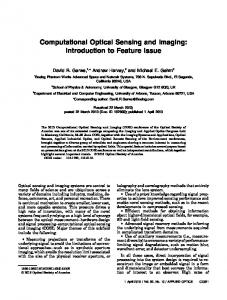
2. MULTI-SCALE IMAGING In 2009, Brady reported a so-called multi-scale imaging approach to lens design that attempts to break the inherent connection between geometric aberrations and aperture size that plagues traditional lens design20. By taking advantage of the superior imaging capabilities of small-scale optics, a multi-scale lens system can exhibit increased field-of-view and image size by simply arraying additional optical elements, similar to a lens array. The resulting overlapping partial images are digitally processed to create a single image with a large field-of-view. This approach has heralded the path to gigapixel imaging and beyond21 using large numbers of discrete cameras and a single ball-lens aperture. Our motivation here however, is to develop a distinct multi-scale approach to demonstrate ultra-wide-field imaging using a single detector array. The basic concept for our approach employs an aspheric objective combined with a segmented corrector element as shown Figure 1. The design approach started from a conventional diffraction-limited f/1, 75mm focal-length, twoelement thermal imaging lens with a field-of-view of 7°. The sensor is assumed to have 640x640 pixels and 25-micron pitch (i.e. 16x16 mm). To increase the field-of-view the imaging system was scaled down by a factor of six and reoptimised and the aberrations at wide field angles are then excessive. The use of a segmented lenslet-array correction element in place of a conventional continuous element enables local correction and near-diffraction-limited imaging, as shown in Figure 2. However, this introduces a clear additional characteristic that light from a single point in the scene is transmitted through the objective and multiple correction elements to the detector, resulting in a complex multi-peaked point-spread function that varies across the field of view.
Proc. of SPIE Vol. 9626 96260Q-2 Downloaded From: http://proceedings.spiedigitallibrary.org/ on 09/29/2015 Terms of Use: http://spiedigitallibrary.org/ss/TermsOfUse.aspx
The imaging process in the multi-scale system can be described by a linear forward model:
y = Hx+n
(1)
where y is the detected image, x is the scene, n is the noise and H is the linear space-variant blur matrix representing the impulse response (PSF) for every point on the image plane. The image y, the scene x and the noise n are represented by lexicographically ordered column vectors. For a square detector with 640x640 pixels on a 25-micron pitch, the size of the system matrix H is [6402x6402] and the size of the column vectors y, x and n is [6402x1]. The system matrix H is relatively sparse, with approximately 175 million non-zero elements (one non-zero element in 1000 elements). An iterative algorithm constructs x using a maximum likelihood estimate. This algorithm is the same as the one used in the reconstruction of multi-aperture images for super-resolution and is particularly appropriate for photon emission processes that follow a Poisson distribution. The algorithm employs an initial guess x0 given by the back-projection of y:
x0 = F Ty ,
(2)
where FT denotes the transpose of F. In each iteration, xn denotes the current estimate and xn+1 the new estimate as defined by:
⎛ y ⎞ x n+1 = x n ⎜ H T ⎟ H xn ⎠ ⎝ .
(3)
Simulated images are shown in the left-most column of Figure 3 for detected signal-to-noise ratios (SNR) of 25 (lower) and 100 (upper) and corresponding recovered images are shown in the right-most column. The resultant images correspond to diffraction-limited image quality across a field of view that has been increased from 7° to 35°, without increasing the overall lens size or element-count, and with a high SNR in the final images.
Figure 1 Multis-cale lens employing a common objective combined with segmented correction. Although thirteen distinct sections are used, manufacture is simplified by the use of only three different designs for the central, mid and outer sections.
A.]
(a)
u
is
it
SPRTIRL FREQUENCY IN CYCLES PER MM
(b)
M
6
A
IB
13
IY
16
SPRTIRL FREql1ENCY IN CYILES PER MM
1A
(c)
6
B
IB
12
14
le
SPRTIFL FREQUENCY LN CYCLES PER
Figure 2 MTF plots for the correctors used for the (a) central (1), (b) mid (2-15) and (c) outer (6-13) correctors
Proc. of SPIE Vol. 9626 96260Q-3 Downloaded From: http://proceedings.spiedigitallibrary.org/ on 09/29/2015 Terms of Use: http://spiedigitallibrary.org/ss/TermsOfUse.aspx
r L
J
Figure 3 Simulated recorded (left column) and reconstructed (right column) thermal images for a detected signalto-noise ratio of 100 (upper row) and 25 (lower row)
3. MULTI-APERTURE IMAGING Using traditional optical design, lens systems can provide a variation in magnification between a central field-of-view (FOV) and the periphery. Such designs are typically limited to variations of a factor of two, and higher ratios encompass dramatic increases in optical complexity and sensitivity to manufacturing tolerances. However, high foveal ratios are attractive for a wide range of applications22-26. Previous approaches include the use of multi-resolution systems using single22 or various sensors23,24, or applications in microscopy25,26. We present a concept for achieving a high foveal ratio while maintaining a reasonable pixel count, system complexity and size. This is based on a multi-aperture approach designed to combine image mosaicking and digital super-resolution: a diversity of images are acquired with different geometrical distortions, and are subsequently projected to reconstruct a wide FOV frame with increased central acuity. Two mechanisms contribute to a higher foveal ratio: the optical distortion effectively introduces non-uniform angular sampling by the sensor, and projection overlap at the central FOV enables digital super-resolution to be attained, further increasing the angular sampling rate. This approach mimics the variation in acuity in biological systems by varying the density of pixel sampling projected onto object space. Our proposed
Proc. of SPIE Vol. 9626 96260Q-4 Downloaded From: http://proceedings.spiedigitallibrary.org/ on 09/29/2015 Terms of Use: http://spiedigitallibrary.org/ss/TermsOfUse.aspx
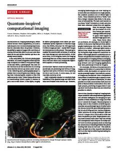
approach is based on the use of a camera array assembled on a printed circuit board (PCB)16,17, along with an array of optical prisms placed in front of the camera apertures as shown in Figure 4. Each camera can have an independent prism angle and orientation, which modifies the region of the global FOV that it covers, although we have grouped the under a reduced number of prisms so as to simplify the manufacture. The cameras have focal length f=2.96mm, f-number 2.8, and the individual FOV is 51°x39. The array achieves a combined global FOV of approximately 100°x80°, as shown in Figure 4(b). In Figure 4 (c) and (d) are shown the effective angular sampling rate in object space, calculated as a density of back-projected pixels from all cameras. The two mechanisms that contribute to increase the foveal ratio can be observed by inspecting Figure 4: the effect of the prisms (that spread-out the pixels towards higher FOVs) and super-resolution from image overlap (very high at the center where the whole set of 25 cameras overlap, and lower in other regions). This can be interpreted as a measure of visual acuity. This is calculated with regards to sampling only, and this acuity will thus only be realized if optical aberrations or diffraction do not set a lower limit. We have, however, previously demonstrated super-resolution imaging employing this camera array17, indicating that the super-sampling of the central FOV, as shown in Figure 4, is possible to a certain degree. Reconstructed images for a book-case scene are shown in Figure 5, including also image components from the central camera and also the super-resolved images of these components. Dashed lines show the region covered by each camera, and makes evident how the global FOV has been doubled from the individual FOV of the central camera. The digital resolution of the output image is decided arbitrarily at the final reconstruction step. Assuming diffractionlimited performance and ideal sub-sampling offsets, the central FOV would be sampled at an ideal maximum angular resolution δϕ = FFOVx FFOVy / ( Np ) , where N=25 is the number of cameras and p=808×604 is the number of pixels per camera (in a single color plane); this would result in a 49MPx image for each color plane in this case. However, this resolution will of course be limited by optical aberrations and registration accuracy, and ultimately by diffraction. Taking this into account and in order not to unnecessarily increase the computational load and memory, we reconstruct images with a slightly lower sampling increase of 4.2. That is, we choose δϕ =0.015°, resulting in a 6667×5333 pixels output image.
HE CI_P CI CI
E E
N
ii
1E13E1 DU,
prism array
40
Vertical FOV (')
>
O
O
u_
O
O
N
ô 20
(b)
-25
0
25
Horizontal FOV ( °)
50
(c)
5000
Angular sampling (Mad)
(a)
°§IiIN gill
Camera array
4000
E. 3000 E
m 2000
1000
(d)
20
30 FOV (°)
40
50
60
Figure 4 (a) Camera array, prism array fitted in front of camera array and (b) 25 overlapping and distorted fields of view of 25 cameras, (c) two-dimensional depiction of sampling density and (d) polar average of sampling density across the field-of-view.
Proc. of SPIE Vol. 9626 96260Q-5 Downloaded From: http://proceedings.spiedigitallibrary.org/ on 09/29/2015 Terms of Use: http://spiedigitallibrary.org/ss/TermsOfUse.aspx
hai
l Gua I1110*1
owMF'
learning óy
.
h`.,...ivr
S
doodling
(a)
(b)
Figure 5 (a) Reconstructed wide-field foveal image and (b) sections components from (above) the central imaging system and (below) the super-resolved image.
4. CONCLUSION We describe here two approaches to computational imaging that employ lenslet arrays, either as correctors or as objectives. Effectively this enables the field-of-view for aberration correction to be reduced sufficiently for each lenslet to enable diffraction-limited imaging, for conventional and foveal imaging where this would not be possible using traditional imaging techniques. This computational imaging approach has strong analogy with conventional communication systems. For example: in hybrid imaging as described in the introduction, optical coding and digital decoding with spatial dispersion of optical spatial frequencies3 is equivalent to the function of an electronic MODEM; multi-aperture imaging is similar to the subNyquist sampling of band-limited temporal frequencies routinely used in high-frequency digitisation; and image recovery for the multi-valued PSF of multiscale imaging is redolent of the use of a Rake receiver to combat multi-path effects in cluttered free-space communication27. Digital communication systems routinely combine these coding and decoding techniques to maximise information transmission through imperfect communication channels to enhance system performance, robustness and logistics. Computational imaging provides the potential to provide the same overall system benefits for imaging. In some cases simplification of optics is possible but with the quid pro quo of more complex digital processing. The unexpected longevity of Moore’s law suggests that convenient computational power will continue to improve exponentially and play an increasing role in the reduction in size, weight and cost of imaging systems – as well as enabling fundamentally new capabilities.
REFERENCES [1] Thompson A.R., Moran J.M., Swenson G.W., [Interferometry and synthesis in radio astronomy 2nd Ed.], Wiley, (2001) [2] Lucotte B., Grafulla-Gonzalez B., Harvey A.R., "Array rotation aperture synthesis for short-range imaging at millimeter wavelengths," Radio Science 44(1006),1-11 (2009) [3] Muyo G. and Harvey A.R., "Decomposition of the optical transfer function: wavefront coding imaging systems," Opt. Lett. 30(20), 2715–2717 (2005). [4] Chi G.W. and George N., "Electronic imaging using a logarithmic asphere," Opt. Lett., 26(12), 875-877 (2001) [5] Mezouari S., Harvey A.R., "Complex amplitude and phase filters for high tolerance to spherical aberration," J. Mod. Opt. 50(14), 2213-2220 (2003)
Proc. of SPIE Vol. 9626 96260Q-6 Downloaded From: http://proceedings.spiedigitallibrary.org/ on 09/29/2015 Terms of Use: http://spiedigitallibrary.org/ss/TermsOfUse.aspx
[1] Mezouari S., Harvey A.R., "Phase pupil functions for control of defocus and spherical aberrations," Opt. Lett., 28( 10), 771-773 (2003) [2] Dowski E.R. and Cathey W.T., "Extended depth of field through wave-front coding," Appl. Opt. 34(11), 1859–1866 (1995) [3] Prasad S, Torgersen T C, Pauca V P, Plemmons R J and van der Gracht J, "Engineering the pupil phase to improve image quality," Proc. SPIE 5108, 1–12 (2003) [4] Vettenburg, T. and Harvey A.R "Correction of optical phase aberrations using binary-amplitude modulation," J. Opt. Soc. Am. A 28(3), 429-433 (2011) [5] Vettenburg T, Bustin N., and Harvey A.R., "Fidelity optimization for aberration-tolerant hybrid imaging systems," Opt. Express 18(9), 9220–9228 (2010). [6] Demenikov M. and Harvey A.R., "Image artifacts in hybrid imaging systems with a cubic phase mask," Optics Express 18(8), 8207-8212 (2010) [7] Demenikov M. and Harvey A.R., "Parametric blind-deconvolution algorithm to remove image artifacts in hybrid imaging systems," Optics Express 18(7), 18035-18040 (2010) [8] Zammit P., Harvey A.R., and Carles G., "Extended depth-of-field imaging and ranging in a snapshot," Optica 1(4), 209-216 (2014) [9] Tanida J. Kumagai T., Yamada K. and Miyatake S. "Thin observation module by bound optics (TOMBO): concept and experimental verification," Applied Optics 40(11), 1806-1813 (2001) [10] Shankar M., Willett R. Pitsianis N., Schulz T., Gibbons R., Kolste R. Robert Te, Carriere J., Chen C., Prather D. and Brady D. "Thin infrared imaging systems through multichannel sampling," Applied Optics, 47(10), 1-10 (2008) [11] Downing J., Findlay E., Muyo G., Harvey A.R., "Multichanneled finite-conjugate imaging," J. Opt. Soc. Am., 29(6), 921-7 (2012) [12] Carles G., Downing, J. and Harvey, A.R., "Super-resolution imaging using a camera array," Optics Letters, 39(7), 1889-92 (2014) [13] Carles G., Muyo G., Bustin N., Wood A. and Harvey A.R., "Compact multi-aperture imaging with high angular resolution," J. Opt. Soc. Am. A 32(3), 411-419 (2015) [14] Young, SS and Driggers, RG, "Superresolution image reconstruction from a sequence of aliased imagery," Applied Optics, 45(21), 5073-5085 (2006) [15] Brady, D.J. and Hagen N., "Multiscale lens design," Opt. Express 17(13), 10659-10678 (2009). [16] Brady, D.J., Gehm, M.E., Stack, R. A., Marks D. L., Kittle D. S., Golish D. R., Vera E. M. and Feller S. D.,, "Multiscale gigapixel photography," Nature, 2012, 486(7403), 386-389 (2012) [17] Belay G., Ottevaere H., Meuret Y.,Vervaeke M., Van Erps J., and Thienpont H., "Demonstration of a multichannel, multiresolution imaging system," Appl Optics 52(24), 6081-6089 (2013) [18] Hua H., and Liu S., "Dual-sensor foveated imaging system," Appl. Optics 47, 317 (2008) [19] Qin Y., Hua H. and M. Nguyen, "Multiresolution foveated laparoscope with high resolvability," Opt. Lett. 38(13), 2191-2193 (2013) [20] Hillman T.R., Gutzler T., Alexandrov S. A., and Sampson D. D., "High-resolution, wide-field object reconstruction with synthetic aperture Fourier holographic optical microscopy," Opt. Expr. 17(10), 7873-7892 (2009) [21] Potsaid B., Bellouard Y., and Wen J.T., "Adaptive Scanning Optical Microscope (ASOM): A multidisciplinary optical microscope design for large field of view and high resolution imaging," Opt. Express 13(17), 6504-6518 (2005) [22] Bottomley G.E., Ottosson T and Wang Y-P.E.,"A generalized RAKE receiver for interference suppression," IEEE J. on Sel. Areas Comm.,18(8), 1536–1545 (2000)
Proc. of SPIE Vol. 9626 96260Q-7 Downloaded From: http://proceedings.spiedigitallibrary.org/ on 09/29/2015 Terms of Use: http://spiedigitallibrary.org/ss/TermsOfUse.aspx