Reâdesign therefore seems attractive for computer support in or-. der to reduce the time of ... PART offers a feature recognition facility for cases in which a CAD.
CONCEPTUAL GRAPHS IN CONSTRAINT BASED RE-DESIGN
O.W. Salomons, F. van Slooten, F.J.A.M. van Houten, H.J.J. Kals Laboratory of Production and Design Engineering Department of Mechanical Engineering University of Twente, The Netherlands
ABSTRACT This paper elaborates on the use of conceptual graphs for the representation of different types of objects and constraints in a re– design support system. Conceptual graphs, or conceptual structures, have been proposed for use in natural language processing and for representing mental models. However, recently they have also been proposed for use in the field of CAD/CAM. Conceptual graphs are graphs with two different kinds of nodes: concepts and conceptual relations. Re–design support involves the modelling of assemblies and components, which on their turn are composed of features and geometric elements. The assemblies, components, features and geometric elements are represented by the concepts in the conceptual graph. The constraints between these entities are represented as conceptual relations. Constraints, such as geometric, kinematic, and manufacturing constraints are represented using conceptual graphs. Thus, conceptual graphs provide for an elegant way of representing both functioning and manufacturing constraints. Constraints are satisfied using a ’multibrid’ constraint satisfaction approach, employing geometry related domain knowledge for the geometry related constraints and an algebraic/numeric approach for the remaining constraint equations. The combination of the constraint satisfaction mechanism and the conceptual graphs allows for a unified way of handling assembly, component and feature related information. Conceptual graphs are not only used in representing assemblies, components, features, and constraints, but also in supporting a mixed top–down and bottom–up design style. Key words: conceptual graphs, constraints, re–design, CAD, CAPP, features. 1 INTRODUCTION In mechanical engineering design a high percentage of all the design tasks can be considered as re–design tasks. Re–design is considered as design with a priori knowledge on the functions and the physical principles to be used in the design. Re–design, although involving a lot of routine tasks, is often expensive and error prone.
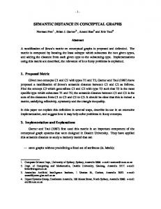
Re–design therefore seems attractive for computer support in order to reduce the time of re–design and to improve quality. However, proper computer support tools for re–design are not available. In re– design, it should be possible to model assemblies and components, taking care of both functioning and manufacturability. Functioning is primarily related to the assembly which is being modelled. Manufacturability is related to single components, focusing on the features of the components. This paper reports on the use of conceptual graphs as an elegant form of representing both functioning and manufacturing aspects. The conceptual graphs are the basic representation form in a prototype of a re–design support tool called FROOM. FROOM FROOM is a prototype of a re–design support system, currently under development at the laboratory of the authors. The development of FROOM has been motivated by the following facts. First, for re–design tasks no proper computer support tools are available yet. Second, CAD tools that integrate well with automated process planning (CAPP) systems are scarcely available. Some academic integrated CAD–CAPP systems, however, are already available, like for instance Next–Cut [CTB92] and QTCII [CJC93]. However, these systems cannot yet cope with industrial practice, especially in the case of commissioner – sub–contractor relationships. In such cases the commissioner not necessarily delivers a feature based CAD model which can directly serve as an input to the process planning functions of the CAPP system of the sub–contractor. The CAPP system that is of particular interest to us, is the PART system [Hou91], which has been developed in the authors’ laboratory. PART offers a feature recognition facility for cases in which a CAD model cannot directly be used in the process planning functions. FROOM aims at offering feature based models that can directly be used in the PART process planning functions. Thus, both the feature recognition and feature based design paradigms are supported. FROOM is an acronym for Feature and Relation based Object Oriented Modelling. It allows the (feature based) modelling of both components and assemblies. Features in the FROOM context can be design form features, manufacturing form features and even abstract features. For a review of feature–based design, refer to [SHK93]. FROOM employs conceptual graphs for knowledge representation, which is a focus of this paper. The conceptual graphs allow re–design support to be provided and facilitate the link with CAPP. However, the latter subject will not be addressed in this paper. Figure 1
shows Froom’s system architecture.
Assem– Con– bly straint model– model– ling ling
Com– ponent model ling
Kernel Modeller Tuning
IOD
Map– ping
Feature Completion
Incomplete feature model
End–user Interface Appli– cation
Inter– face
Database Interface Database
System Manager UI Fig. 1 System architecture of FROOM; IOD means interactive object definition. As can be seen from figure 1, two different kinds of users are distinguished: end–users and system manager users. End–users are the designers who create models of assemblies, components etc.; they perform the actual design tasks. System managers customize the system to a certain application domain, company and user (group). They define the features to be used, the catalogues from which selections can be made etc.. For these two different user groups, separate user interfaces are available. In the modelling module of FROOM, components, assemblies and constraints can be modelled by the end–user, see figure 1. This module has access to the kernel modeller, which offers the basic geometry processing functionality. In FROOM, the commercially available ACISTM kernel modeller is used for this. The application module includes the possible mappings to applications and the applications themselves. An example of an application might be manufacturability evaluation. For more details on FROOM refer to [SKSHK93], [SSHK93] [Sal95] and [SJSHK95]. Although this paper will not discuss the CAD–CAPP link, or more specifically the FROOM–PART link, in detail, it seems obvious that features play an important role in this. As a matter of fact, feature definition can be seen as a crucial element in the CAD– CAPP link [SJSHK 94], [Sal95] and [GSSHK95]. Figure 2 illustrates the potential importance of features in general and feature definition in particular for the CAD–CAPP link. Feature definition as part of FROOM (i.e. CAD) is discussed later on in this paper. Recently, FROOM has been extended in order to support collaborative engineering. The extended architecture, resulting from this is shown in figure 3. In the center of figure 3, several FROOM systems can be distinguished, containing all the functionality previously addressed in figure 1. However, only the (local) database (LdB) and (local) constraint management (LCM) functionality are shown in figure 3 because these are important to collaborative engineering tasks. It must be noted that in addition to several FROOM systems, there could also be several other systems such as PART or other CAPP systems in the center of figure 3. Apart from features, which support CAD–CAPP integration in a more or less formal way as shown in figure 2, cooperation between designers and process planners supports CAD–CAPP integration in an informal way. Thus, several heterogeneous systems are to be combined in a collaborative engineering environment. The main additions to already existing functional modules are: a communication mediator, project leader functionality, a global constraint manager, engineering data management in combination with filters and project management func-
Feature Based Design
Manufacturing feature model
Process
mapping Manufacturing feature model
Tolerancing Assembly modeling
plan– all recognized ning Feature Recognition
Design feature model Non–feature model Assembly model Design history info.
Non feature based/ Conventional solid modeling
Cost, manufacturability info.
?
Feature Identification
Feature Definition
CAD
CAPP
feature info
other info
Fig. 2 : The central role of features and feature definition in a CAD–CAPP link, feature definition drives feature based design and feature recognition. Left side represents CAD functionality as part of FROOM, the right side represents CAPP functionality as a part of PART. project management module
project leader functionality
single end–user CAD/CAPP system LdB
LCM
communication mediator
Global Constraint Manager
EDM & filter facility (virtual) central shared dataBase Fig. 3 Extended functional model for collaborative product development (LdB = Local dataBase, LCM = Local Constraint Manager, EDM = Engineering Data Management). tionality. This paper, however, does not extend on this, the reader is referred to [Sal95] for more details. Organization of the paper This paper is organized as follows. Section 2 reviews representation issues in CAD while section 3 reviews the use of constraint satisfaction techniques in CAD. Then, in section 4, the selections made
in FROOM regarding representation issues and the use of constraint solvers are elaborated. Sections 5 through 7 describe details of some FROOM modules in which both representation issues and constraint satisfaction issues have been implemented: assembly modelling, tolerancing and feature definition. In these modules, conceptual graphs are used as a representation scheme. Finally, in section 8 conclusions and recommendations are presented. 2 REPRESENTATION ISSUES IN CAD In CAD, both the design object and the design knowledge need to be represented. A design object can be an assembly or a single component. The design knowledge can be related to the design object or to the design process. In the following, the focus is on design object representation. 2.1 Design object representation The design object, in mechanical engineering, can be either a component or an assembly. Features relate to a component’s shape; they are part of the design object (component). As geometric information is the core of the information contained in product models, the representation of a feature’s form is an important issue. Form features are usually represented geometrically by solid modelling representation schemes: B–rep, CSG, hybrid B–rep/CSG or non– manifold. Assemblies are often represented by means of graphs. In these graphs usually two important items are present: the objects (components and their faces if the component geometry is fully specified) and the relations between the objects. Design object knowledge can be represented in different ways, for example using logic, rules and structured forms. Logic and rules often can only be used for representing simple facts. However, more complex structures occur in reality; and these have to be modelled as objects with characteristics and relations etc.. The objects and relations can be taken as the basis of knowledge representation. Examples are: frames, scripts, semantic networks and conceptual dependencies. Features can be used to describe the design object as well as to capture design object knowledge [SHK93]. Features provide a means to represent objects both symbolically and geometrically. Many different representation formalisms and languages have been proposed in literature. Standards such as STEP have been put forward in order to support the exchange of product model data. However, these standards have deficiencies. They cannot satisfy the information sharing needs of engineering collaborators, for instance [OCGT94]. Logic based conceptual schema languages are advocated for design object representation because of their expressiveness and well established foundations in mathematics, linguistics and philosophy [OCTG94]. Because logic based languages have associated model and proof theories, they can support knowledge based systems applications and other applications that require advanced reasoning capabilities much better than Express or Entity– Relation Based schema languages [OCTG94]. One such logic based conceptual schema language is the representation by conceptual graphs. Conceptual graphs have been selected for knowledge representation in FROOM. Because of this, approaches employing conceptual graphs in CAD are elaborated in the following. 2.2 Conceptual graphs for representing the design object Conceptual graphs, or conceptual structures, have been proposed for use in natural language processing and for representing mental models by Sowa [Sow84]. Conceptual graphs have a close connection with logic, well established foundations in mathematics, as well as links with linguistics and philosophy. Therefore, the number of
applications of conceptual graphs in other domains than that of natural language processing and representing mental models is increasing. One of these domains is that of (re)design support in CAD, which is also the focus of this paper. Conceptual graphs are graphs with two different kinds of nodes: concepts and conceptual relations. Conceptual graphs are therefore called bipartite. Sowa defines a conceptual graph as follows [Sow84]: A conceptual graph is a finite connected bipartite graph. The two kinds of nodes of the bipartite graph are concepts and conceptual relations. Every conceptual relation has one or more arcs, each of which must be linked to some concept. If a relation has n–arcs it is said to be n–adic and its arcs are labelled 1,2..n. The term monadic is synonymous with 1–adic, dyadic with 2–adic and tri–adic with 3–adic. A single concept may itself form a conceptual graph, but every arc of every conceptual relation must be linked to some concept. monkey
agnt
eat
obj obj
inst spoon
walnut part
matr
shell
Fig. 4 An example of a conceptual graph, redrawn from [Sow84].
The concepts in a conceptual graph are usually denoted by rectangles and the conceptual relations are usually denoted by circles. Figure 4 shows a simple example of a conceptual graph, taken from [Sow84]. The graph in figure 4 may be read as ”a monkey eating a walnut with a spoon made out of the walnut’s shell”. The concepts are monkey, eat, walnut, spoon and shell while the conceptual relations belong to a pre–defined set of relations [Sow84]. The directions of the arcs in figure 4 depend on the relation definitions, as defined by Sowa [Sow84]. Schmekel reported on the representation of product data in a computer system for the conceptual design of mechanical products, based on the use of conceptual graphs [Sch92]. The work by Schmekel is based on the general principles of design by Suh [Suh90] and the systematic principles of design by Pahl and Beitz [PB84]. Closely related to the work by Schmekel is the work by Andersson [And93a,b]. Andersson reports on a design language based on engineering terminology called CANDLE – also used by Schmekel – that is based on the conceptual graphs as described by Sowa [Sow84]. The concept nodes in CANDLE represent entities, attributes, states and events while the relation nodes show how the concepts are interconnected. Schmekel classifies relations into part, port, connection, equality, attribute and constraint relations [Sch92]. There are some deviations as compared to Sowa [Sow84]: the graphical symbols are somewhat different and entities and relations have so–called ”roles”. Roles represent e.g. the procedures or rules that are utilized for the synthesis and analysis of various solutions during the design work. Object oriented classifications of both concepts and conceptual relations are provided. Constraints are represented in CANDLE by attaching them to the conceptual relations. Billo et al. reported on the use of conceptual graphs for feature representation and definition [BHR89], [Bil89]. Feature representation is defined here as representing both the individual (form) features and the relations between the individual features that constitute
a component. Billo et al. would like to bring some more rigor into feature representation by using conceptual graphs. By doing this, feature recognition and feature mapping or conversion would be made easier. A simple example of feature transformation to Group Technology coding is given. The feature representation used by Billo et al. – in case of prismatic features – consists of face concepts and adjacency relations between them. The face concepts are part of the general feature concept. However, it is not fully clear whether other relations between faces are also possible such as for example perpendicular, concave, convex, parallel etc.. Other, more complex features are defined using conceptual graphs for sweeps and ruled surfaces. Hashim et al. use conceptual graphs as a means for functional reasoning in generating design variants [HJP93]. Ullman [Ull93] has a similar notion of objects and relations as Schmekel [Sch92], Andersson [And93a], Hashim [HJP93] and as described in this paper. However, Ullman does not report on the use of conceptual graphs for representing objects and relations [Ull93]. 3 CONSTRAINTS IN CAD Design has often been said to be constraint oriented. Constraints usually indicate limitations of the range of possible solutions. Most often, constraints are regarded as algebraic equations. These constraints can affect geometry, but also forces, stresses etc.. Therefore, in many approaches, different types of constraints were transformed into algebraic equations. 3.1 Constraint satisfaction Satisfaction of algebraic/numeric constraint equations could be performed by using constraint propagation, or more advanced techniques such as variational modelling [Ser87] or the use of optimization techniques (e.g. [TJ93]). Recently, a trend can be distinguished in which it is in some cases preferred to not translate every possible constraint into an equation. This is because by using domain knowledge, a lot of the problems related to conventional numeric iterative solvers, such as numeric instability, can be overcome. It is therefore preferred to solve the constraint(s) directly with domain specific knowledge. This seems to be particularly advantageous for the satisfaction of geometric constraints which are of interest to design and process planning. An example of such a way of solving (nominal geometry related) geometric constraints is degrees of freedom (DOF) analysis as proposed in [Kra92]. In assembly modelling both constraint approaches have been applied. References applying the algebraic/numeric approach in assembly modelling are: [AP75], [PAB80], [Pop87], [LG85] [LA85], [KL87] and [Mul87]. References applying to assembly modelling employing the geometry based approaches are: [LN91] [Kra92] [AKC92] and [SR93]. In feature modelling and definition, constraints also play an important role. Most often, feature related constraints are related to dimensions and tolerances. These constraints are also most often transformed into numeric/algebraic equations and solved by means of rules, numeric iterative techniques etc.. However, recently it has been proposed to use geometric domain knowledge when solving feature related constraints, e.g. [SR93], [SBRU94]. In this respect, Shah et al. distinguish a procedural and a declarative approach towards feature based design, where the procedural approach is the older approach and the descriptive approach the newer one based on
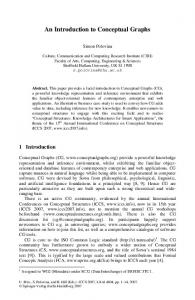
using geometric domain knowledge. In the following we will focus on the satisfaction of geometric constraints using domain knowledge some more. Satisfaction of nominal geometric constraints using domain knowledge Conventional geometry constraints solving packages use iterative numerical techniques like for instance Newton–Rhapson. Kramer, however, works from the geometry directly instead of using numerical techniques. Therefore, Degrees of Freedom (DOF) analysis is a novel, more intuitive technique for solving geometric (nominal geometry) constraint problems and it shows to be superior to conventional, iterative numeric techniques. The technique relies on a layered approach to solving a constraint problem. The first step is to reason symbolically about how to assemble a collection of ”ghost” parts. The next step is to use the resulting assembly plan to guide the solution of the equations resulting from an algebraic description of the constraint problem. This assembly plan guides the solution of the equations, by implementing actions as simple equations which are solved in stylistic ways [Kra92]. Although Kramer’s DOF analysis was originally proposed for simulating kinematic mechanisms, it can be used in assembly modelling and feature modelling as well [AKC92], [SR93], [SBRU94]. Satisfaction of variational geometric constraints using domain knowledge In the previous cases the geometric constraints are related to nominal geometry. The ”satisfaction” of variational geometry constraints (tolerances) may also employ the use of domain knowledge, an example is e.g. [CR93]. The study of displacements that leave a surface invariant is relevant to the tolerances specified on surfaces; tolerances are only meaningful in directions other than those that leave a surface invariant with respect to itself. Using the theory of the set of displacements (a background in kinematics, similar to Kramer) by Hervé [Hervé 78], Clément et al. have proven that there are only seven elementary face types. The 7 elementary classes of surfaces are: spherical, planar, cylindrical, helical, surfaces of revolution, prismatic and ”any” surfaces. When these 7 face types are combined, 28 cases of combination can be found. These combinations of faces are also called TTRS: Technologically and Topologically Related Surfaces. There is a finite number (w44) of reclassifications of TTRS which denote the theoretical number of different tolerances (types). On the basis of TTRS, a computer system can automatically propose tolerance types using an assembly model (geometric tolerances). Also reference (datum) elements can be determined (semi–)automatically. These elements are called MGDE: Minimum Geometric Datum Element; see table 1 for the MGDEs related to each elementary surface as proposed by Clément et al.. The same set of MGDE is used for determining the datum of composed TTRS. When two elementary surfaces are combined in a TTRS, the resulting TTRS can be classified into one of the seven basic classes depending on the types of surfaces involved and the geometric relations between them. See table 2 for the reclassifications of TTRS. In this approach, tolerances are represented vectorially, in so–called torsors or matrices, which enable tolerance analysis. This has been addressed in [Gau94] and [RGDD94]. 3.2 Conceptual graphs for constraint representation Apart from the satisfaction of constraints, constraints need to be represented. In many cases, graphs are used in the representation of
elementary sur- MGDE element face sphere point plane
plane
cylinder
line point and line or: line and plane point and line line and plane point and line and plane
helical rotational prismatic any
MGDE symbol
other low level geometric entities. Assemblies are constituted by components which are constituted by features which in turn are built up of faces. Within FROOM, these objects can be very abstract or very concrete. Relations in FROOM can exist between any combination of the different types of objects, e.g. assembly–assembly, assembly–feature, component–feature or feature–feature etc.. The relations often indicate functioning or manufacturing constraints. The relations can also be very abstract or very concrete. FROOM allows an initial set of objects and relations, defined by the system manager, to be refined by the end–user. Like in the work by Schmekel [Sch92] and Andersson [And93a], taxonomies of both objects and relations are present. Figure 5 shows the combined taxonomy that is currently partly implemented. contextItem
Table 1 The MGDE associated with each elementary surface (after [CDR91]).
object
relation
assembly component feature energy_flow spatial information connect standard generic form feature
.... abstract feature face–face
atomic compound
manufacturing against align/fit contact orient parallel–offset
Fig. 5. Taxonomy of objects and relations in FROOM.
Table 2 Cases of tolerancing between surfaces, including the resulting MGDEs (redrawn after [CDR91]). Note that the concentric relation in some cases – e.g. in case of the surface of revolution – sphere association – is not literally a concentric relation; it represents the intersection or coincidence of both MGDE. constraints, e.g. [Ser87], [TJ93], [Kra92]. In the following, the relation between constraints and conceptual graphs is detailed further. Sowa describes the use of actors in dataflow graphs as an extension of conceptual graphs for representing sequencing problems [Sow 84]. This concept could be used for representing constraints. Billo et al. use these actors in dataflow graphs [BHR89], [Bil89]. However, they are only used for the definition of relatively simple parameter dependency constraints. Schmekel [Sch92] and Andersson [And93a,b] also represent parameter constraints in conceptual graphs. However, in their approach the constraints are attached to the conceptual relations. Schmekel distinguishes integrity, quantitative, qualitative and finite constraints [Sch92]. 4 REPRESENTATION ISSUES AND CONSTRAINT SATISFACTION IN FROOM 4.1 General representation approach using conceptual graphs In FROOM, the objects which are of concern during the (re)design process are considered as concepts in a conceptual graph. Concepts can be assemblies, components, features and even faces and
The most important deviations of the conceptual graphs in FROOM from the conceptual graphs as defined by Sowa [Sow84] are the following: – Only assemblies, components, features, faces and other geometric objects are valid concepts that are visualized in the graph. Attributes for instance, are part of the object oriented descriptions of concepts and relations and are usually not shown in the conceptual graph (unless the constraint network of parameter constraints is shown). – The relations used in FROOM are monadic, dyadic or tri–adic. Dyadic relations are most commonly used. Monadic relations are mainly used for defining subgraphs which can represent alternatives. From these, the end–user can select the alternative which will finally be instantiated (joined) in the overall graph (see also figures 7 and 8). As a consequence, if a join on a relation has to be performed there should be two monadic relations in the subgraph. If a join on a concept has to be performed, no monadic relations should be part of the subgraph [Sal95]. Monadic relations are also used in tolerance presentation. This also holds for tri–adic relations. – Directed arcs – as shown in figure 4 – are only used when necessary. Often relations just denote a general connection relation like ”component A is connected to component B”. Usually, ”component B is connected to component A” holds equally well, so that the arcs could have been directed in both directions. In these cases, arcs are omitted. – In the graphical notation of concepts and relations, sometimes other symbols are used than the small rectangle or circle. Symbolic icons are sometimes used instead of the circles or blocks for reasons of clarity; see for instance figures 7 and 8. Especially system users are allowed to build graphs by themselves, e.g. as part of the feature definition module (section 7). End– users usually use the pre–defined graphs to facilitate their work. The graphs are automatically checked for correctness using the rules for conceptual graphs as put forward by Sowa [Sow84]. The positioning of the graph elements is also automatically performed by some sim-
ple positioning algorithms. However, the user is allowed to manually modify the positions of the graph elements.
method is the only constraint satisfaction method of the Global Constraint Management module of figure 3.
4.2 Constraint satisfaction in FROOM
Because three different constraint satisfaction techniques were selected, the interdependence between these techniques should be considered. If one constraint type is changed, added or deleted and the change is evaluated in the corresponding constraint solver, the effect that it can have on the other constraint types has to be determined. Changes of constraints belonging to one constraint type involve the necessity of reevaluating constraints of other constraint types. A unified ”multi–brid” constraint solver, combining the different constraint satisfaction techniques, offering highly intelligent support to the users must be developed. Moreover, in order to support a more sophisticated constraint based communication facility in FROOM’s collaborative product development facility, such a multi–brid constraint solver also seems highly desirable. However, at present such a unified constraint satisfaction method has not been realized yet. Preliminary ideas as to how this can be achieved are provided in [Sal95].
There exist several definitions of constraints. The following notion of constraint is used within the FROOM context: A constraint is either imposed on a single object or represents a desired relationship among two or more objects. In FROOM, the main types of constraints that are considered are: nominal geometry constraints, variational geometry constraints (tolerances) and parameter constraints. All these constraints can be represented using conceptual graphs. The nominal geometry constraints are comparable to Schmekel’s integrity constraints, the tolerance constraints to Schmekel’s qualitative constraints and the parameter constraints to Schmekel’s quantitative and finite constraints. A further constraint classification within FROOM discerns five types of constraints: 1. assembly geometry constraints: these constraints are defined between (faces of) components to enable the modelling of an assembly. In FROOM, the assembly constraints are using symbolic constraints like ”against”, ”align/fit”, ”contact”, ”orient”, and ”parallel–offset” (figure 5). 2. feature internal geometry constraints: these are (non variational) constraints within a feature, between the elements that constitute the feature; faces, edges etc.. Feature internal constraints currently applied in FROOM are for example: parallel, perpendicular, adjacent and co–axial.
5 ASSEMBLY MODELLING IN FROOM Assemblies consist of components and/or sub assemblies. The assembly modelling functionality of FROOM as part of the architecture in figure 1 is depicted graphically in figure 6. In the following mainly the assembly representation functionality and assembly constraint satisfaction functionality are addressed. For assembly representation, conceptual graphs were selected. The conceptual
3. feature external geometry constraints: these are (non variational) constraints between feature elements and non–feature elements within a component. These feature types are similar to the feature internal geometry constraints: parallel, perpendicular, adjacent, etc.. These constraints are important for defining how features have to be instantiated and how they will behave.
component models
4. variational geometry constraints: these constraints can be considered as tolerance constraints and they can be defined between faces, between features or inside features or even on a single surface. However, tolerances are often related to functions and hence, the assembly model is important as well.
detailed assembly user
5. parameter constraints: these constraints can be defined either by the system manager or the end–user. They can be regarded as algebraic equations and affect dimensions, geometry, forces, stresses etc.. Parameter constraints can relate to assemblies, features and tolerances. The first three types of constraints are related to nominal geometry. Degrees of Freedom Analysis, as proposed by Kramer [Kra92] (and also used in a different form by Liu et al. [LN91]) has been adopted for solving these constraints; see section 5. Solving variational geometric constraints is based on work by Clément et al. [CR93]; see also section 6. Presently, parameter constraints in FROOM are simple linear, uni–directional parameter dependency constraints. This, however, does not necessitate the use of conceptual graphs for constraint representation. A more advanced parameter constraint satisfaction mechanism is under development based on [TJ93]. The conceptual graphs can be used for the representation and visualization of the constraint network. In this case, the variables or parameters are the concepts while the constraints can be represented as the conceptual relations. In the present implementation, this constraint satisfaction
abstract structure
assembly (constr aint) presentation
assembly constrai nt satisfaction
user action
assembly representation
storage
assembly model
user action assembly constraint specificacompotion nent/ assembly retrieval Fig. 6 Functional decomposition of the assembly modelling functionality. graph representing the assembly consists of the objects that make up the assembly and the connection relations between these objects. Figures 7 – 8 show the current end–user interface of FROOM, i.e. the assembly (constraint) presentation functionality. The upper left window is the geometry window in which interactive geometry manipulation actions similar to those in current CAD systems can be performed. In the upper right window, the context window, a conceptual graph is shown. In the following, conceptual graphs will also be referred to as context structures. The graph reflects the actual internal representation of all objects and relations. The concepts in the graph correspond to the geometry objects in the geometry window.
There is a bi–directional association between the context window and the geometry window. The two main windows allow a mixed top–down and bottom–up design style. Bottom–up support is given in the geometry window similar to existing CAD systems. In the geometry window, component modelling using features is supported as well as assembly modelling by relating previously defined components to one another. Top–down support is given from the context window: if an object or relation has the color green, then something predefined can be found on a lower level which can be detailed further. This is illustrated in figures 7 and 8. Figure 7 shows a relation between a shaft and a gearwheel that has been predefined by the system manager (the connect–1 relation). This relation can be refined by the end–user to become a key connection; see figure 8. Because of the associativity between the geometry and context windows, a mixed top–down and File Geometry Constraints Context. Custom. Design_Hist shaft1 connect–1 gearwheel combination connect–2 shaft2
Fig. 7 The two main windows of the FROOM end–user interface. bottom–up design style can be adopted. An example of bottom–up support that has been implemented in FROOM is the possibility to relate existing components relative to one another. This is achieved by so–called low level relations or mating relations. At present, the following low level relations have been implemented in FROOM: against, align/fit, contact, orient and parallel offset. The implementation of these relations (assembly constraint satisfaction) is based on a slight modification of the work presented by Liu and Nnaji [LN91] and [Kra92]. This approach allows for automatically determining the kinematic degrees of freedom of each component and for automatically determining the functional surfaces, which is important for tolerancing. File Geometry Constraints Context. Custom. Design_Hist conn. keyway conn. key conn. keyway conn. connect–1–alt1 Ok Cancel
shaft1 connect–1 gearcom bination connect–2 shaft2
Fig. 8 FROOM end–user interface, alternative selection.
6 COMPUTER AIDED TOLERANCING IN FROOM Computer aided tolerancing functionality as part of the FROOM constraint management functionality (figure 1) is shown schematically in figure 9. The main functions of a computer aided tolerancing assem- functional requirements bly design knowledge requirepart tolerances + asments sembly tolerances Tolerance specificamanufacturtion ing knowledge, cost Tolerance info etc. analysis assembly model
Tolerance info on assembly feasibil- synthesis ity & quality
optimized part (+ assembly) tolerances, cost info
assembly model (extended with tolerancing info) (geometric) tolerances datums assembly feasibility assembly quality cost manufacturing info inspection info
Figure 9 The main functions: tolerance specification, analysis and synthesis and their connections (tolerance representation is not shown). module that have been distinguished are tolerance specification, tolerance representation, tolerance analysis and tolerance synthesis [Sal95], [SJSHK95]. Tolerance specification is the activity of specifying (geometric) tolerances; defining the tolerance types and related tolerance values. Tolerance specification is preferably carried out in conformance with the tolerancing standards (e.g. ISO 1101, ANSI Y14.5M). A lot of approaches (possibly correct in the theoretical and mathematical sense) for the computer representation of tolerances as proposed in literature do not sufficiently comply with the international standards. Tolerance analysis is a method to verify the proper functioning of the assembly after tolerances have been specified. Tolerance analysis is usually performed by verifying assemblability; the feasibility of assembly (fit) and by verifying if the specified clearances between parts are still met; the quality of assembly (clearance). Tolerance synthesis is regarded as optimization and completion of the (functional) tolerance specification, taking manufacturing and inspection aspects into account. For tolerance specification, essentially the method as proposed by Clément et al. [CDR91] was adopted. The kinematic loops of functional faces in the (conceptual) assembly graph are used for the determination of tolerance types. Figure 10 gives an example of a proposal of a tolerance type based on an analysis of the conceptual assembly graph using the TTRS concept. After the tolerance types and the datum elements have been determined automatically, the user has to specify the tolerance values manually. For tolerance representation, the TTRS approach [CDR91], [CR93] has been adopted because it seems to be in accordance with the standards, offers for a correct mathematic model of tolerances and enables tolerance analysis and synthesis. For tolerance analysis, the torsor approach offers a mathematically correct description of tolerance zones and can be used for tolerance analysis applications. Thus, the approach as described in [Gau94] together with that of [RGDD94] has been selected [Sal95].
cy relationship. At present, the following relations are also supported: adjacent (convex, concave, tangential), perpendicular, parallel and co–axial. In fact, these relations can be viewed upon as feature internal constraints. By properly defining these relations, both functioning and manufacturing constraints related to features can be expressed. Features can be defined in three modes which can be used intermittently [SJSHK94]: 1. by editing a conceptual graph representing the feature (figure 12). 2. by allowing direct graphic interactive geometric input, e.g. making a sketch in 2D and extruding or sweeping it. 3. by indicating the feature elements on a solid. The feature related internal and external geometric constraints are satisfied by means of DOF analysis which allows for mixing the above modes of feature definition. The remaining constraints can be expressed as equations which can be solved by means of a simulated annealing parameter solver according to [TJ93]. Fig. 10 The system proposes a parallelism tolerance between the two gear holes in the housing. A combination of the macro–DOF’s as proposed by Kramer [Kra92] and the micro–DOF’s (tolerances) as described in [CR93] is used in order to reduce the sets of constraints. This approach, as well as the tolerance synthesis approach is detailed further in [SJSHK 95] and [Sal95]. The presentation of tolerances adheres to standards but conceptual graphs can be used for this purpose as well. 7 FEATURE DEFINITION IN FROOM The feature definition functionality which has been developed for use in FROOM’s Interactive Object Definition (IOD) module is indicated in figure 11. As in the work by Billo et al. [BHR89], shape elements features
In the graph editing approach, the user instantaneously gets generic geometry in the geometry window. This is considered to be very important as users usually do have geometry in their minds of which the graph is an abstraction. The user interface for feature definition is currently extended to enable direct geometric input, e.g. by means of sketching, with concurrent automatic conceptual graph generation. Presently available concepts are ”planar face”, ”cylindrical face” and ”conical face”. Future extensions will have to be made to the available concepts. For instance including all 7 elementary face types as distinguished by Clément et al. must be supported. Also, the definition of free–shaped features (sweeps, ruled surfaces etc.) and abstract features will have to be accounted for. The feature definition capabilities of FROOM are further elaborated in [SJSHK94]. Fea-
cf#4 feature presentation
feature constraint satisfaction
feature representation
pf#1
cf#1
storage
hierarchy
pf#2
user action
feature constraint specification
user
solidify
customized features customized hierarchy
pf#4
cf#3
pf#3
cf#2
naming user action
auxiliary
feature(element)/hierarchy retrieval
Fig. 11 A functional decomposition of the feature definition functionality. [Bil89], feature representation in FROOM is based on the use of conceptual graphs. However, more relations can be defined between the individual faces constituting a feature other than just an adjacen-
Fig. 12 Feature definition in FROOM. ture definition for both feature based design and manufacturing (automatically deriving feature recognition code) is elaborated in [GSSHK95].
8 CONCLUSIONS AND RECOMMENDATIONS The focus of this paper is on the application of conceptual graphs and constraints in a re–design support tool, called FROOM. Conceptual graphs have been applied for representing assemblies, components, features, low level geometric objects and constraints. Conceptual graphs are used as a means of supporting a mixed top–down and bottom–up design style. Conceptual graphs can represent both functional and manufacturing related information. Therefore, they offer opportunities for supporting (re)design. Three main types of constraints were distinguished: nominal geometry constraints, variational geometry constraints and parameter constraints. For each constraint type, different constraint satisfaction mechanisms are employed; degrees of freedom analysis, TTRS method, and a parameter equation solver. In the future a unified constraint solver will be developed in which mutual influences of different constraints are adequately managed.
[GSSHK95] Geelink R., Salomons O.W., Slooten F. van, Houten F.J.A.M. van, Kals H.J.J., Unified feature definition for feature based design and feature based manufacturing, subm., to ASME CIE’95 conf., 1995. [HJP93] Hashim, F.M., Juster, N.P., de Pennington, A., Generating design variants based on functional reasoning, proc. of ICED ’93, The Hague, Vol. 1, 1993, 60–67. [Hou91] Houten, F.J.A.M van, PART, a computer aided process planning system, PhD thesis, Univ. of Twente, 1991. [KL87] Ko H., Lee K., Automatic assembling procedure generation from mating conditions, Computer–Aided Design, vol. 19, no.1, 1987, 3–10. [Kra92] Kramer, G.A., 1992, Solving geometric constraint systems, a case study in kinematics, The MIT Press, Cambridge.
ACKNOWLEDGEMENTS
[LA85] Lee K., Andrews G., Inference of the positions of components in an assembly: part2, Computer–Aided Design, vol.17, no 1, 1985, 20–24.
This research is supported by the Technology Foundation (STW: a Dutch foundation funded by the Dutch government).
[LG85] Lee K., Gossard D.C., A hierarchical data structure for representing assemblies: part1, Computer–Aided Design, vol.17, no.1, 1985, 15–19.
REFERENCES
[LN91] Liu, H–C., Nnaji, B.O., Design with Spatial Relations, J. of Manufact. Systems, Vol. 10, No. 6, 1991, 449–463.
[AKC92] Anantha R., Kramer G.A., Crawford R., An architecture to represent over, under and fully constrained assemblies, ASME Winter Annual Meeting, 1992, 233–244.
[Mul87] Mullineux G., Optimization scheme for assembling components, Computer–Aided Design, vol. 19, 1987, 35–40.
[And93b] Andersson, K., CANDLE – A new tool for conceptual design, proc. of ICED’93, The Hague, 1993 Vol.1, 45–52.
[OCTG94] Olsen G.R., Cutkosky M., Tenenbaum J.M., Gruber T.R., Collaborative engineering based on knowledge sharing agreements, proceedings 1994 ASME Database Symposium, Sept. 11–14, Minneapolis MN, 1994, to be obtained via: http://www–ksl.stanford.edu/knowledge–sharing/papers/in dex.html#olsen asme–94.
[AP75] Ambler A.P., Popplestone R.J., Inferring the positions of bodies from specified spatial relationships, Artificial Intelligence, 6, 1975, 157–174.
[PAB80] Popplestone R.J., Ambler A.P., Bellos I.M., An interpreter language for describing assemblies, Artificial Intelligence, 14, 1980, 79–107.
[BHR89] Billo, R., Henderson, M., Rucker, R., Applying conceptual graph inferencing to feature–based engineering analysis, Comp. in Industry, vol. 13, 1989, 195– 214.
[PB84] Pahl, G., Beitz, W., Engineering Design, A systematic approach, Springer Verlag, 1994.
[And93a] Andersson, K., A design language based on engineering terminology, PhD thesis, R.I.T., Stockholm, 1993.
[Bil89] Billo, R.E., An object–oriented modeling methodology utilizing conceptual graphs for form feature definition, PhD thesis, Arizona State University, 1989. [CDR91] Clément A., Desrochers A., Rivière A., Theory and practice of 3D tolerancing for assembly, CIRP seminar on Computer aided tolerancing, Penn State University, USA, May 1991. [CJC93] Chamberlain M.A., Joneja A., Chang T–C., Protrusion– features handling in design and manufacturing planning, computer aided design, vol. 25, no. 1, 1993, 19 – 28. [CR93] Clément, A., Rivière, A., Tolerancing versus nominal modelling in next generation CAD/CAM system, CIRP sem. Comp. Aided Tolerancing, Cachan, 1993, 97–113. [CTB92] Cutkosky M.R., Tenenbaum J.M., Brown D.R., Working with multiple representations in a concurrent design system, Journal of Mechanical Design, Vol. 114, 1992, 515 – 524. [Gau94] Gaunet D., Modèle formel de tolerancement de position, contributions à l’aide au tolerancement des mécanismes en CFAO, in French, PhD thesis, ENS de Cachan, February 1994.
[Pop87] Popplestone R.J., The Edinburgh Designer System as a framework for Robotics, Proc. 1987, IEEE Int. Conf. on Robotics and Automation, Vol. 3, 1987, 1972–1977. [RGDD94] Rivière A., Gaunet D., Dubé I., Desrochers A., Une approche matrcielle pour la représentation des zones de tolérance et des jeux, to appear, 1994. [Sal95] Salomons O.W., Computer Support in the design of mechanical products, constraint specification and satisfaction in feature based design for manufacturing, PhD thesis, University of Twente, 1995, also available on WWW: http://utwpue.wb.utwente.nl/~otto/thesis/ [SBRU94] Shah J.J., Balakrishnan G., Rogers M.T., Urban S.D., Comparative study of procedural and declarative feature based geometric modeling, proceeedings IFIP WG 5.3 Conf. on Feature modeling and feature recognition in advanced CAD/CAM systems, Vol. 2, Valenciennes, 1994, 647–671. [Sch92]Schmekel, H., A system for conceptual design based on general and systematic principles of design PhD thesis, Royal Institute of Technology, Stockholm, 1992.
[Ser87] Serrano, D., 1987, Constraint management in conceptual design, PhD thesis, Cambridge, MIT.
[Sow84] Sowa, J.F., Conceptual Structures, information processing in mind and machine, Addison–Wesley, 1984.
[SHK93] Salomons, O.W., Houten, F.J.A.M. van, Kals, H.J.J., Review of research in feature–based design, J. of Manufacturing Systems, Vol.12, No.2, 1993, 113–132.
[SR93] Shah J.J., Rogers M.T., Assembly modeling as an extension of feature based design, Research in Engineering Design, Vol. 5, 1993, 218–237.
[SJSHK94] Salomons, O.W., Jonker, H.G., Slooten, F. van, Houten, F.J.A.M. van, Kals H.J.J., Interactive feature definition, IFIP WG5.3 Conf. on Feature Modelling & Recognition in Adv. CAD/ CAM systems, Vol. 1, Valenciennes, 1994, pp 181–205 .
[SSHK93] Salomons, O.W., Slooten, F. van, Houten, F.J.A.M. van, Kals, H.J.J., A computer support tool for re–design, a prototype system resulting from applying a methodic design approach, proc. of ICED’93, The Hague, Vol.3, 1993, 1559–1570.
[SJSHK95] Salomons O.W., Jonge–Poerink H.J., Slooten F. van, Houten F.J.A.M. van, Kals H.J.J., A computer aided tolerancing tool based on kinematics analogies, accepted for 4th CIRP international workshop on computer aided tolerancing, Tokyo, April 1995.
[Suh90] Suh, N.P., The principles of design, Oxford University Press, New York 1990.
[SKSHK93] Salomons, O.W., Kappert, J.H., Slooten, F. van, Houten, F.J.A.M. van, Kals, H.J.J., Computer support in the (re)design of mechanical products, a new approach in feature based design, focusing on the link with CAPP, in: Knowledge Based Hybrid Systems, Mezgár I., Bertók P. (eds.), IFIP Trans. B–11, North Holland, 1993, 91–103.
[TJ93] Thornton, A.C., Johnson A., Constraint specification and satisfaction in embodiment design, proceedings of ICED’93, Vol.3, The Hague, 1993, 1319–1326. [Ull93] Ullman, D.G., A new view on function modeling, proceedings of ICED ’93, The Hague, Vol.1, 1993, 21–29.