Delphi Automotive Systems, Electronic Data Systems (EDS) ... and even process re-engineering efforts, both the European and American automotive industries.
Concurrent Function Deployment -- Three-Dimensional House of Values (HOV): Parts I and II Biren Prasad Delphi Automotive Systems, Electronic Data Systems (EDS) Automated Concurrent Engineering (ACE), P.O. Box 250254 West Bloomfield, MI 48325-0254, USA In this paper, an alternate framework for deployment called Concurrent Function Deployment (CFD) is described. The methodology exploits the independence of units that manifest itself in Strategic Business Units, TQM, and Total Enterprise Management concepts that are now emerging. It considers parallel deployment, as contrasted to the phased deployment (for example, American Supplier Institute’s QFD concept [Sullivan, 1988], in meeting life cycle values. It is not based on using a single measurement, such as “Quality” as in QFD. The present approach is more versatile than Akao’s GOAL/QPC concept. In the present setting, ASI’s QFD emerges as a special case of Concurrent Function Deployment. It enables the Planners and Strategic Decision Makers early-on to deal with tradeoffs among the crucial factors of artifact values. Six concurrent values, namely Functionality (Quality), Performance (X-ability), Tools & Technology (innovation), Cost, Responsiveness, and Infrastructure (delivery) are considered simultaneously rather than serially. Three dimensional Value Characteristics Matrices (VCM) are employed to ensure that both the company and the customers’ goals are optimally met. Introduction While manufacturing philosophies have changed drastically during the eighties, the pace of such transitions from concept to practice has been very slow. Despite painful restructuring, reorganization, and even process re-engineering efforts, both the European and American automotive industries have failed to attain parity in product cost, productivity, or throughput with Japanese producers and transplant operations. Earlier published work showed assurances that the competitive gaps could be closed using Quality Function Deployment (QFD) or similar programs causing a change in the organizational effectiveness and culture. This motivated abandonment of many traditional function values in favor of employee empowerment and autonomous multi-functional team-working. Many such combinations have been tried with QFD, along with Pugh’s concept [Clausing, 1994], voice of the customer (VOC), and product development team (PDT). They are discussed in Volume I of CE Fundamentals [Prasad, 1986a]. Though each QFD combination provided new opportunities and contributions towards cost and productivity improvements, such programs have encountered difficulties in making a parent company globally competitive. Furthermore, the gains that would seem obvious and feasible through the exploitation of QFD and its combination (in quantifiable competitive sense) have not always been fully realized. The application of QFD is a fairly old (over two decades old) innovation [Hauser and Clausing, 1988]. Historically, the concept of QFD was introduced by Japanese [refer for instance, Mizuno and Akao, 1978; and Aswad, 1989] in 1967. It did not emerge as a viable methodology until 1972 when it was applied at the Kobe shipyards of Mitsubishi Heavy Industries [see for instance, Hales, Lyman and Norman, 1990; Taguchi, 1987; and ASQC, 1992] in Japan. American Supplier Institute (ASI) and 1
GOAL/QPC (Growth Opportunity Alliance of Lawrence, Massachusetts/Quality Productivity Center) [see for instance, Akao, 1990; and King, 1987] have done a great job in publicizing it in the United States. QFD was designed originally to take the Voice of the Customer (called customer objectives) and translate them into a set of design parameters that can be deployed vertically top-down through a serial four-phase process [Sullivan, 1988]. The four phases, known as ASI’s four-phase process are: Product Planning, Parts Deployment, Process Planning and Production Planning. The overall objective of QFD, which was “Quality” deployment when introduced in 1967, today is still the product’s quality. Emphasis on quality was also the reason why it was named Quality Function Deployment by the Japanese [Crosby, 1979; Deming, 1986; Taguchi and Clausing, 1990]. Recently Don Clausing and others have introduced some structural changes in the way the QFD information is arranged. The new arrangement is commonly called the extended House of Quality [Hales, Lyman and Norman, 1990; Taguchi and Clausing, 1990]. However, the emphasis has not changed. 1
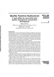
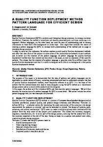
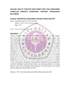
Components of QFD This extended House of Quality (HOQ) consists of eight fundamental areas, all of which are not essential (see Figure 1). Figure 2.23 of Volume I [Prasad, 1996a] identifies the names of each area, and the door example in Section 2.8.2.3 (Figure 2.24 of volume I [Prasad, 1996a]) gives a glimpse of its full potential. In the following section, we visit each room of the extended HOQ and examine its essential features. Figure 2.23: Expanded House of Quality (HOQ) [Ref. Prasad, 1996a]
2
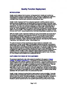
Figure 2.24: Use of Quality Function Deployment: A Door Example [Ref: Prasad, 1996a]
3
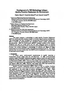
S en sitiv ity M atrix
K ey P ro d u ct C h aracteristics (K P C s)
C R s P rio rity o r W eig h in g F acto rs
C u sto m er R eq u irem en ts (C R s)
C o rrelatio n M atrix
W eig h in g M atrix
P ro d u ct C h aracteristics T arg ets
T arg et M atrix
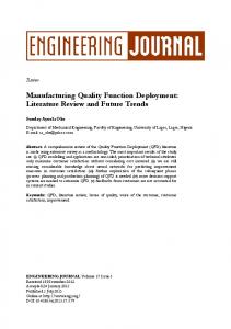
Figure 1: QFD Extended House of Quality -- List-vectors and Matrices 2
Limitations in Deploying QFD
Early on, when Japanese became successful in bringing cars to market in record time, many automotive world leaders mistakenly assumed that their success was solely because of technical tools. This explains the initial flurry of activities (with QFD, SPC, Taguchi, Pugh, Kaizon, etc.) that American industries went through during 1980s. As many American automotive industries failed on this front, manufacturers began to unearth the cause of their failures. It did not take very long to realize their apparent short-sightedness. They discovered that many of the barriers to global competitiveness were rooted in their assumptions, i.e., basing their PD3 decisions on “quality” while ignoring other important aspects such as costs, design for x-ability, tools and technology, infrastructure, which have not been deployed simultaneously. QFD does not specifically address the cost, tools & technology, responsiveness (time-to-market) and organizational aspects in the same vein as it does to the "quality" aspect (see Figure 1). While some consider the product design process as being independent from technology, design-for xability, cost and responsiveness, the reality is that these are tied together by a common set of product and process requirements. Design process only provides a product design from the perspectives of performance (i.e., quality). The product design performance requirements drive the product selection (including system, subsystems, components, parts and material selection) process and influence the selection of the fabrication (process and production) method. Others have argued that while performing Quality FD, designers could choose to include requirements, which belongs to considerations other than quality in the original customers’ list of HOQ [Dika and Begley, 1991; Carey, 1992; Kroll, 1992]. Accomplishing this through a conventional deployment process is not simple. Working on the multiple lists of requirements as part of a single function deployment (say under Quality) is a much tougher problem. 4
First, it would be a complex undertaking considering just the size of the resulting relational matrices. Second, deploying them serially would be a long drawn process. Third, cascading the requirements all together as we did in the case of Quality functions would be so large that it would be difficult to handle. Fourth, there is no way of insuring that the design obtained through this combinatorial Quality FD process would not result in a sub-optimized design, i.e., a product particularly designed for characteristics related to quality. What is required in optimizing an artifact is designing with respect to all important functions that characterize a “world-class product” today. Normally in actual practice, information for these measurements is independently obtained and design often proceed in parallel. Paralleling allows the combinatorial problems to be addressed in sizable chunks, which in turn can be handled by a number of specialized work-groups comfortably. Parallel deployment of values would allow concurrent teams to work independently, thus reducing the PD3 cycle-time. Conventional deployment cannot account for the increasing complexities of our product and the conflicting requirements that need to be addressed. As a result the best efforts of the concurrent team simply do not result in products that optimally meet customer requirements. It is not because the teams are not able to work closely, but the deployment vehicle is not robust enough to accommodate multiple functions deployment simultaneously. Conventional deployment lacks the vigor while implementing simultaneously various conflicting value characteristics such as cost, responsiveness, quality, etc. In the absence of any better deployment vehicle, the team repeats the conventional deployment process for each value one at a time. This elongates the PD 3 cycle-time into a multi-year ordeal. 3
Concurrent Product Development
The first step in creating a great product is an understanding of what exactly makes a product great. Kim Clark defines a great product as one that meets all pertinent characteristics that are required to ensure product integrity. This is discussed further in Prasad [1986b]. Generally, development of a new artifact does include considerations for several life cycle values that are pertinent to meeting the customers' requirements. Many of these values are independent, i.e. there is very little or no interaction between them. Through the course of investigations and study, the author has found that the deployment of many artifact functions (values) can proceed in parallel with what we know toady as "quality FD." Examples are: X-ability (performance), tools and technology, cost, responsiveness and infrastructure. Generally, these functions or values are independently specified or estimated. The results of experience can be used to specify the requirements and expectation for each of the values in parallel without having to wait until a deployment of “quality FD” is complete. 4
Concurrent Function Deployment
In Reference [Prasad, 1996b], we have expanded the original definition of QFD to include parallel deployments. This provides a method to consider the deployment of competing values simultaneously. We have called this approach Concurrent Function Deployment (CFD). The intent of CFD is to incorporate “Voice of the Customers” into all nine phases of the product development cycle, through Mission definition, Concept Definition, Engineering and Analysis, Product Design, Prototyping, Production Engineering and Planning, Production Operations and Control, Manufacturing and finally into Continuous Improvement, Support and Delivery (see Figure 4.2, Volume I [Prasad, 1986a]). In other words, CFD is customer driven PD 3 methodology. 5
CFD is a Concurrent Engineering methodology that enforces the notion of concurrency and deploys simultaneously a number of competing artifact values, not just the “Quality as found in QFD.” The artifact value deployment is through all its life-cycle phases. If a specification chart is being developed for the product, the taxonomy for requirements and constraints (RCs) must reflect all value considerations. RCs thus include customer requirements (CRs) , VOCs and all types of WHATs that one may encounter. There are many value characteristics (VCs) for artifact, such as quality, X-ability, tools and technology, costs, responsiveness, infrastructure, etc. Such taxonomy will ensure that all important aspects for product and process design have been identified and included. The focus of CFD is on systematically capturing product information, such as, market competitive analysis and customer satisfaction rating, analyzing these ratings to improve product functionality (say a X-ability part) and then adding an array of values that are important to the customers and to the company. CFD, thus, ensures concurrent product development. CFD breaks the multi-year QFD ordeal by allowing work-groups to work concurrently on a number of conflicting values and compare their notes at common check points. CFD is a simple and powerful tool that leads to long range thinking and better communication across several value functions. Prasad [1996b] presents a methodology for concurrently deploying a line of value objectives for successive product refinements leading to a “world-class” category. Also, since each TVM’s life cycle 6
value meets only a partial set of artifact specifications, the characteristics of the chosen TVM values will dictate the life-cycle needs to manufacture or fabricate the product. 5
CFD Methodology
Concurrent Function Deployment (CFD) is a methodology that allows designers and manufacturing engineers to communicate early and work in parallel during various stages of a PD 3 process. One critical new tool to facilitate this early communication is “house of values,” which is a concept similar to the “house of quality” that was introduced in Akao's QFD. However, the term “values” is not used here to mean just “quality.” It ranges from quality as it was in QFD to other values, such as X-ability, tools and technology, cost, responsiveness, Infrastructure and other similar type functions. The concept gives rise to a line of concurrent houses; namely House of Quality, House of X-ability, House of Tools and Technology, House of Cost, etc. House of Quality, thus, becomes a degenerate or a special case of this series --“House of Values” -- template. 5.1
Three-dimensional House of Values (HOV)
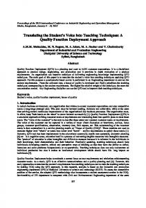
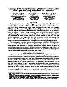
The basic tool of CFD is the “relational matrix” concept. Matrices are schemata to generically define and directionally relate multiple lists of identifiers, often referred as line- or list-vectors. The basic matrix of CFD is the “house of values,” so named to keep resemblance with “house of quality” that forms one of the many objectives of CFD [Prasad, 1986b]. The relational matrix in CFD translates the corresponding requirements and constrains (RCs) into value characteristics (VCs). Figure 2 is a schematic view of a “House of Values (HOV)” template.
7
HOWs versus HOWs HOWs
WHYs
WHATs
WHATS versus HOWs
WHATs versus WHYs
HOW MUCHes
HOWs versus HOW MUCHes Figure 2: Typical House of Values (HOV) Template
This template (HOV) has 8 rooms. Four of the rooms form the basic perimeters of the house. These are two row-rooms: WHATs and HOW-MUCHes, and two column-rooms: HOWs and WHYs. Concurrent HOV also encompasses relationships between these four list-vectors resulting into four “relational matrices.” These are:
HOWs versus HOWs WHATs versus HOWs HOWs versus HOW-MUCHes WHATs versus WHYs.
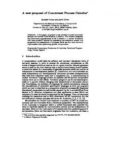
The relationship between CFD components are shown in Figure 3. The three-dimensional matrix takes the form of three roofs and three relational matrices as shown in Figure 3. It has three list vectors: artifact values (AVs), value characteristics (VCs), and requirements and constraints (RCs) list. Eight elements of AVs, nine elements of VCs and three major elements of RCs vectors are shown for example purposes. These lists may contain any number of values as necessary. The three relational matrices are: RCs versus VCs 8
RCs versus AVs AVs versus VCs
Figure 3: Relationship between the CFD components [Ref. Figure 1.7, Prasad, 1996b] This completes the concurrent deployment of artifact's values AVs along the three axes.
9
Figure 4: Comparison of QFD and CFD
Concurrent Function Deployment (CFD)
Quality Function Deployment (QFD)
5.2
QFD is a phased (or a serial) process
CFD is a concurrent process
QFD is an inside-out focussed
CFD is an outside-in holistically focussed
QFD works with the pieces of objects (car door, roof, hinges, etc.)
CFD works with the whole product rather than its pieces
QFD is mainly successful in solving pockets of problems
o CFD is used in conjunction with company mission deployment principles
QFD is a problem solving process (e.g., a rusty car door, a leaking seal, etc.) or sometimes a redesign process
A systematic approach to handling all life-cycle values relevant to the product
QFD focuses on technical parameters that are not necessarily looped back to the whole product
Customer requirements are considered separately from QCs values
QFD provides a technical importance rating for quality characteristics (QCs)
CFD provides a value index - cummulative effectiveness rating
QFD deals with pieces of product or pieces of requirements
CFD optimizes the system with consistency of purpose as target goals
Because of its serial nature of processing, QFD is perceived to take a long time
Because of its concurrent processing, CFD is conceived to be faster than QFD
Life-cycle Deployment
Figure 4 compares the QFD and CFD approaches in great depth. QFD is actually a subset of CFD. In traditional deployment processes (as in QFD), quality is generally associated with manufacturing and for which several quality measurement tools, such as SPC, QPC, CMM, etc., are typically employed. For instance, activities such as performance measurements, dimensional control, and others, are often used to check quality compliance during manufacturing. In reality, such efforts need not be limited to only manufacturing. Quality is not just a manufacturing problem alone. It is a cumulative outcome of decisions that are made during an entire product life-cycle. It is, therefore, important to affect all such decisions. What would be a more appropriate place to affect these decisions than during the individual processes where these decisions are made? In CFD process, quality begins with the quality of the introduced requirements and constraints (RCs). RCs, in this context, are not only those requirements which are specified by the customers, but also includes those that are introduced directly by the cooperating CE teams [Prasad, Morenc and Rangan, 1993] (see Figure 2.22 of Volume I). The burden of poor outcome of a design has 10
been shifted from the work-groups expertise in product manufacturing to the teams’ choice (or selection) of RCs at each CFD transformation step. If appropriate methods can be employed in systematically classifying, deploying, and solving the transformed problems, the assurance of VCs’ considerations becomes merely a scheduling and distribution job. Quality considerations are ensured by the proper selection of RCs and methods for solving the constrained problems. Satisfaction of RCs and VCs at each transformation state is what constitute a product’s “values deployment.” By following this methodology, the taxonomy of transformation leads to a “world-class valued” product, the quality characteristics of which are appropriately distributed across the various levels of transformation. At each level, differences between proposed RCs and the computed outputs provide a measure of the differences that exist among alternative trial designs. Dealing with quality at loop level is straightforward, since problem definitions (number of RCs, inputs, and the transformation matrix) are small and are at a manageable scale. Satisfaction of RCs during these early loop levels (say feasibility or product synthesis loops) is easier when problem definition is more explicit in form than when the product is somewhat mature, say, after the product has crossed several decision boundaries. The next section illustrates a degenerate case of CFD, that is of deploying a quality FD through a CFD trio process. This concept is virtually equivalent to a QFD. 5.3
Quality FD
Products are often divided into logical hierarchical blocks depending upon their complexity levels. Different parallel teams can work in these different hierarchical groups. Work-groups at each level can work concurrently. Some dependencies can exist between the levels. Establishing common quality standards for communications and definitions of VCs can allow parallel work-groups to work concurrently. The most commonly employed quality characteristics, Yij, are [Prasad, 1993]: Where Yij for i=1 (Quality FD) and j=1, 5 are: 1.1 Assembly 1.2 Sub-assemblies 1.3 Components 1.4 Parts 1.5 Materials, etc. Figure 3 shows the above quality characteristics spanned along the axial (y-axis) dimension.
11
Figure 3: Concurrent Function Deployment: X-Axis – WHATs and HOWs [ See Figure 1.5, Prasad, 1996b] Figure 5 illustrates the CFD concept of vertically deploying (along the z-axis) quality RCs often embedded in the Voice of the Customer. The three-tier deployment structure is shown in Figure 5 for quality FD. Tier 1 is for Product Planning, Tier 2 is for Process Planning, and Tier 3 is for Production Planning. The same three-dimensional trio process is repeated for each tier. For example, during product planning, customer requirements (CRs) or WHATs are related to key quality characteristics, for which a list of WHYs and a list of HOW-MUCHes are then identified. HOWs define the desired key product characteristics (PtCs) of a product to counter the WHATs. WHYs are the overall evaluation criteria used within the organization to define acceptability of the product. Targets for the PtCs (HOW-MUCHes) are established based upon competitive benchmarks and the customer’s competitive assessment. Such deployment methodology is followed for tier 2 and the tier 3 trio sequences.
12
Figure 5: Linked CFD House of Values for Quality -- Vertical Deployment (Z-axis) [ Fig. 1.9, Prasad,
1996b] In Figure 6, the “quality” value for CFD tier 1 is further spanned axially (along y-axis) into its characteristic (VCs). This axial expansion corresponds to the five VCs for quality that were listed in Figure 3. The axial expansion of the Product Planning tier (Yij, j=1, 5; levels I.1 through level I.5) uses the PtCs defined in tier 1 to evaluate alternatives and filter a design that meets most of the 13
customers’ demands. At the end of Tier 1 (level I.5), a set of Product PtCs is identified that represents best of the class (see Figure 5). Process planning (tier 2) deals with selection of process concept and identification of critical operation parameters, here called as Key Process Characteristics (PsCs) , which can cause the product PtCs identified in tier 1 to be satisfied. Production Planning (tier 3) identifies Production PnCs (control requirements, maintenance requirements, mistake proofing, education and training issues, etc.) in line with the process (PsCs) identified in tier 2.
Figure 6: Linked CFD House of Values for Quality: Axial Deployment (y-axis) [See Fig. 1.10, Prasad, 1996b] 6.
Concluding Remarks
In the example described herein only a three-tier trio (horizontal- axial-vertical) structure for CFD is shown. This is the most common [Prasad, 1986b]. However, such a CFD structure can have as many tiers as needed. In these diagrams, the filtering process is shown through a solid pipeline connecting the “characteristics” (HOWs) room to the WHATs room (see Figure 6). It ensures that VCs (namely PtCs, PsCs and PnCs) that are critical to meeting the product, process, and production objectives are given proper and early attentions (during y-axis deployment). It also ensures that HOWs are further deployed into their root or key characteristic factors during the subsequent vertical tiers (z-axis deployment). 14
7.
References
Akao, Y.A., 1990, “Quality Function Deployment - Integrating Customer Requirements into Product Design”, Cambridge, MA: Productivity Press Inc. Also in Quality Deployment: A series of Articles Edited by Yoji Akao, Japanese Standards Association and translated by Glen Mazur, GOAL/QPC, Methuen, Mass. ASQC (American Society for Quality Control), Automotive Division, American Supplier Institute (ASI), GOAL/QPC, 1992, Transactions from the fourth symposium on Quality Function Deployment (QFD), June 15-16, 1992, Novi, Michigan. Aswad, A., 1989, “Quality Function Deployment: A Tool or a Philosophy,” SAE Paper No. 890163, Society of Automotive Engineers, International Congress and Exposition, February 27-March 3, 1989. Carey, W.R., 1992, Tools for Today’s Engineer -- Strategy for Achieving Engineering Excellence: Section 1: Quality Function Deployment, SP-913, Proceedings of the SAE International Congress and Exposition, February 24-28, Detroit, Michigan, SAE Paper # 920040. Clausing, D., 1994, Total Quality Development: A Step-by-step Guide to World-Class Concurrent Engineering, New York: ASME Press. Crosby, P.B., 1979, Quality is Free: The Art of Making Quality Certain, New York: McGraw Hill. Deming, W.E., 1986, Out of Crisis, 2nd Edition, Cambridge MA: MIT Center for Advanced Engineering Study. Dika, R.J., And R.L. Begley, 1991, “Concept Development Through Teamwork -- Working for Quality, Cost, Weight and Investment, ” SAE Paper # 910212, Proceedings of the SAE International Congress and Exposition, Feb. 25-March 1, Detroit, MI.: SAE, pp. 1-12. Hales, R., D. Lyman, And R. Norman, 1990, “Quality Function Deployment and the Expanded House of Quality,” Ohio: International TechneGroup Inc., Technical Report, pp. 1-12. Hauser, J.R., And D. Clausing, 1988, “The House of Quality,” Harvard Business Review, Volume 66, No. 3, May-June, pp. 63-73. King, B., 1987, Better Designs in Half the Time - Implementing QFD Quality Function Deployment in America, Methnen, Massachusetts: GOAL/QPC. Kroll, E., 1992, “Towards Using Cost Estimates to Guide Concurrent Design Processes,” PED -Vol. 59, Concurrent Engineering, ASME, edited by Dutta, Woo, Chandrashekhar, Bailey and Allen, Proceedings of the Winter Annual Meeting of ASME, Nov. 8-13, 1992, Anaheim, CA.: ASME Press, pp. 281-293. Mizuno, And Y. Akao, 1978, (ed.): Quality Function Deployment, JUSE (published in Japanese). Prasad, B., R.S. Morenc, and R.M. Rangan, 1993, “Information Management for Concurrent Engineering: Research Issues,” Concurrent Engineering: Research & Applications, Vol. I, No. 1, March 1993. 15
Prasad, B., 1993a, "Product Planning Optimization using Quality Function Deployment", Chapter 5 In AI in Optimal Design and Manufacturing book, edited by Z. Dong, and series Editor Mo. Jamshidi, Prentice Hall, Englewood, NJ, 1993, pp. 117-152. Prasad, B., and Neal Strand, 1993b, A flowchart-based Methodology for Process Improvement, in Quality Concepts '93 World Class Manufacturing Book, Engineering Society of Detroit, 1993, pp. 5374. Prasad, B., 1995a, JIT Quality Metrics for Strategic Planning and Implementation, International J. of Operations & Production Management, Special Issue on Modeling and Analysis of Just-in-Time Manufacturing Systems, Guest Edited by S.K. Goyal and A. Gunasekaran, Volume 15, No. 9 (October), 1995, pp. 116-142. Prasad, B., 1995b, A Structured Approach to Product and Process Optimization for Manufacturing and Service Industries, International Journal of Quality & Reliability Management, Special Issue on Quality Improvements in Manufacturing and Service Industries: Recent Trends and Perspectives, edited by A. Gunasekaran, J. Lyu and H.-J. Liu, Volume 12, Number 9 (October), 1995, pp. 123-138. ‘ Prasad, B., 1996a, Concurrent Engineering Fundamentals: Integrated Product and Process Organization, Volume 1, Upper Saddle River, NJ: Prentice Hall PTR, Inc. Prasad, B., 1996b, Concurrent Engineering Fundamentals: Integrated Product Development, Volume 2, Upper Saddle River, NJ: Prentice Hall PTR, Inc. Sullivan, L.P., 1988, “Quality Function Deployment,” Quality Progress, Vol. XXI, No. 6, (June). Taguchi, G., And D. Clausing, 1990, “Robust Quality,” Harvard Business Review, Vol. 68, No. 1, Jan.-Feb., pp. 65-75. Taguchi, S., 1987, “Taguchi Methods and QFD: Hows and Whys for Management, American Supplier Institute, Dearborn, MI: A.S.I. Press.
16