Conformal Mapping for Multiple Terminals Weimin Wang1,*, Wenying Ma2, Qiang Wang1, Hao Ren3 1
State Key Laboratory of Optical Technologies on Nano-Fabrication and Micro-Engineering, Institute of Optics and Electronics, Chinese Academy of Science, Chengdu 610209, China 2 College of Communication Engineering, Chengdu University of Information Technology, Chengdu 610225, China 3 School of Electrical, Computer, and Energy Engineering, Arizona State University, Tempe, Arizona 85281, USA Abstract Conformal mapping is an important mathematical tool in many physical and engineering fields, especially in electrostatics, fluid mechanics, classical mechanics, and transformation optics. However in the existing textbooks and literatures, it is only adopted to solve the problems which have only two terminals. Two terminals with electric potential differences, pressure difference, optical path difference, etc., can be mapped conformally onto a solvable structure, e.g., a rectangle, where the two terminals are mapped onto two opposite edges of the rectangle. Here we show a conformal mapping method for multiple terminals, which is more common in practical applications. Through accurate analysis of the boundary conditions, additional terminals or boundaries are folded in the inner of the mapped rectangle. Then the solution will not be influenced. The method is described in several typical situations and two application examples are detailed. The first example is an electrostatic actuator with three electrodes. A previous literature dealt with this problem by approximately treat the three electrodes as two electrodes. Based on the proposed method, a preciser result is achieved in our paper. The second example is a light beam splitter designed by transformation optics, which is recently attracting growing interests around the world. The splitter has three ports, one for input and two for output. Based on the proposed method, a relatively simple and precise solution compared with previously reported results is obtained.
*
Correspondence to
[email protected]
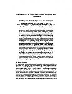
Introduction Conformal mapping, as one of the most powerful tools of complex analysis, have been applied in many mathematical and physical fields. It mapped the unknown region onto a solvable structure, is especially suitable for two-dimension problems, such as transmission lines [1-5], integrated circuit components [6-11], electrostatic actuators [12-16], transformation optics [17-21]. Fig. 1a shows a representative example of electrostatics. The solid lines on the closed curve represent the surface of conductors and they are equipotential lines. The dashed lines represent electric field lines. Through a conformal mapping, the interior of the closed curve, i.e., the shaded region, is mapped onto a perfect (fringe effect-free) parallel-plate capacitor (Fig. 1b), whose electric field distribution is well known. Then the capacitance, potential, field, and charge of the unknown region can be obtained through an inverse mapping. The same method can also be utilized to magnetostatic field, all types of flow problems, transformation optics, and so on. Besides parallel-plate capacitor, other structures with known potential distribution, e.g., Figs 1c and 1d, can also be used as the mapped objects. A
a
b
D
C
A
B
B D C
c
d
V+ V-
V+
V-
Figure 1 | A representative example of conformal mapping. a, The shaded region is a unknown structure. The solid lines are conductors and the dashed lines are electric field lines. b, The unknown structure is mapped conformally onto a perfect parallel-plate capacitor. c, Another structure with known potential and field distribution besides parallel-plate capacitor. The negative real axis has a potential of V+ and the positive real axis has another potential of V-. Thus the concentric circles whose center is origin are electric field lines and the straight lines through the origin are equipotential lines. d, The third structure with known potential and field distribution. Its electric field lines and equipotential lines are just opposite to those of c.
It is easy to see that this method is only suitable for two terminals with electric potential difference, pressure difference, optical path difference, etc. For more than two terminals, it is common to reduce the structure to two terminals by symmetry considerations. However, in many practical problems the structures are complicated and asymmetric. A general way is to approximately treat some terminals as one terminal and the other terminals as another [16, 22, 23]. If the potential of the multiple terminals in the former or the latter are different, they are approximately treated as the
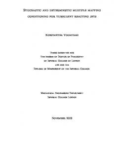
same firstly [14, 15, 24]. Then the problem is simplified to two terminals. In this study a strict and exact conformal mapping for multiple terminals with arbitrary potential or net charge is proposed and described. Based on this proposed method, two application examples are detailed and compared with previous literatures. Mapping method The method is described in electrostatic problem, where the terminals are the surface of conductors. Taking three conductors as an example, as indicated in Fig. 2a, there are two situations for the extra conductor EF, i.e., a given potential or a given net free charge. First we consider that the conductor EF has the same potential with one of the other two conductors. Without loss of generality, we assume the conductors EF and CD have the potential V and the conductor AB is grounded. It is easy to see that the directions of electric field lines BC and FA are from high potential to low potential, as shown as the solid arrows in Fig. 2a. On the other hand, due to the fact that the vertices D and E have the same potential, the direction of the electric field line DE is as the hollow arrows shown in Fig. 2a. In other words, from vertex D to vertex E along the dashed line DE, the potential first decreases and then increases. Therefore, a point D’ exists at which the minimum potential occurs in line DE. As DE is an electric field line, the mapped line of DE in the perfect parallel-plate capacitor should be perpendicular to the mapped line of the conductors. Based on this analysis, the mapped capacitor of Fig. 2a is shown in Fig. 2b. The position of D’ can be achieved through the relationship that the conductors CD and EF have the same potential, i.e., the length of DD’ should be equal to the length of D’E. After the mapping is constructed, the electric field and potential in this folded rectangle is the same with a conventional rectangle. Then the original problem is solved. A
F
a
b
E
F
ED
C
c
C
E F
D
B
D E
D A
B
A
B
C
d
D F
C
E
D
e
F E
C
H B
A
B
D E
F
E
D A
f
G
A
G
C
D B
Figure 2 | The conformal mapping for multiple conductors. a, The extra conductor EF has the same potential with CD. Thus the directions of the electric field lines BC, DE, and FA are as the arrows shown. b, The mapped perfect capacitor of a. The dashed lines DD’ and D’E overlap, although they are drawn separately to show that the structure is closed. c, The mapped capacitor of a when the conductor EF is floating and has a zero net charge. d, A possible mapped result of the situation that the potential of the conductor EF is different from the other two conductors. e, Another possible mapped result of the
situation d. f, An example of the conformal mapping for four conductors.
Second we consider that the conductor EF is floating and has a zero net charge. Now the conductor EF is an equipotential line and its potential is unknown. The equipotential line is parallel to the two conductors in a parallel-plate capacitor. Thus the corresponding mapped structure is shown in Fig. 2c. Given that the charge of EE’ has the opposite polarity to the charge of E’F, and they have the same area density of charge, the length of EE’ should be equal to the length of E’F. Therefore, the position of E’ and the potential of EF can be solved through this relationship. Then this situation is also solved. Next let us consider a more complex situation, e.g., the potential of the conductor EF is different from that of the other two conductors. For example, the potential of EF is smaller than that of CD and larger than that of AB. Under different structural parameters, the unknown region can be mapped onto Fig. 2d or 2e. Because the ratio of the potential of EF to the potential of CD equals to the ratio of the length of FA to the length of BC, the position of D’ (Fig. 2d) or E’ (Fid. 2e) can be solved, and which one of Figs 2d and 2e is the right mapped pattern will be determined. Then the mapped structure can be calculated in terms of two capacitors in parallel connection. As for the situation that the conductor EF is floating and has a non-zero net charge Q, it is similar to the above situation, only that the net charge is known and the potential is unknown. Therefore the mapped pattern is also Fig. 2d or 2e. Given that all conductors have the same and uniform area density of charge in a perfect parallel-plate capacitor, the position of D’ or E’ can be determined by the following equations
LEF V L Q BC V LE'F - LEE' Q LBC
forFig.d (1)
forFig.2e
where V is the potential of CD, is the dielectric constant of the shaded region and L is the length between corresponding vertices. All possible situations for three conductors have been discussed. If there are more conductors, obviously more edges will be folded in the inner of the mapped rectangle. One of the mapped results for four conductors is shown in Fig. 2f. It should be noted that here the positions of D’ and G’ are general determined by a system of quadratic equations with two unknowns. Above we only discussed that the region to be solved is mapped onto a rectangle. Acturally, due to the Riemann mapping theorem [25], any simply connected region, e.g., Fig. 1c, can be mapped conformally onto a rectangle. As for multiply connected region, a general structure is shown in Fig. 3a. Assuming that V-