PAPER
Consideration of a Variable Frequency Energy Conversion System for Marine and Onshore Wind Energy Extraction AUTHOR
ABSTRACT
Clifford R. Merz College of Marine Science, University of South Florida
Wind energy is now well established as a viable means of generating electricity. It has good prospects of becoming increasingly competitive as volume production and improved technology further reduce capital costs and as its environmental advantages become more valued. Conversion devices used to recover energy from the wind are typically referred to as wind turbines or wind machines. Examination of the literature finds numerous wind turbine designs in use, depending upon the intended size and application. This paper discusses the concept of a permanent magnet synchronous generator (PMSG)-based variable frequency energy conversion system (VFECS) for wind and potentially water energy extraction operations. Keywords: alternative power generation, marine renewable wind energy, variable frequency wind turbine design, permanent magnet synchronous generator design, wind machines
Overview
W
ind energy is now well established as a viable means of generating electricity. It has good prospects of becoming increasingly competitive as volume production and improved technology further reduce capital costs and as its environmental advantages become more valued. Conversion devices used to convert energy from the wind into electricity are typically referred to as wind turbines or wind machines. Excluded in this discussion are windmills, which are typically used for water pumping operations. This paper provides an overview from the electrical perspective. Examination of the literature finds numerous wind turbine designs in use, depending upon the intended size and application. Types of wind turbine generators installed over the past 20 years generally fall into the following four categories: ■ Type 1: Induction or fixed speed generator; ■ Type 2: Wound rotor induction generator with adjustable rotor resistance; ■ Type 3: Doubly fed induction generator (DFIG); and ■ Type 4: Permanent magnet synchronous generator (PMSG) with full power convertor.
218
Type 1 and type 2 wind turbine generators are still available from turbine manufacturers but are not as often utilized as are type 3 and type 4 generators for marine applications. Considering journal scope and article page constraints, this paper is focused on present and future category types 3 and 4 wind turbine generator designs. The paper begins with (1) a general background section covering fundamental electricity concepts, followed by sections on (2) wind turbine generator operation, (3) specifics related to PMSG wind turbines, (4) the type 4 variable frequency energy conversion system (VFECS) conceptual design, and (5) recommendations.
General Background Fundamental Electricity Discussion Electric current (I ) is the flow of an electric charge per unit time. An elec-
Marine Technology Society Journal
tric charge flows when there is a voltage (V) present across a device. The international system of units (SI) for measuring voltage is the volt, defined as the electric potential difference between two points or the difference in electric potential energy of a unit test charge transported between two points, measured in joules per coulomb (Electrochemistry Encyclopedia, 2013). The SI unit for measuring electric current is the ampere, defined as the flow of charges at a rate of 1 coulomb/second. A flow of positive charges gives the same electric current and has the same effect in a circuit as an equal flow of negative charges in the opposite direction. In metals, which make up the wires and other conductors in most electrical circuits, the positive charges are immobile, and the charge carriers are electrons. In electric circuits, this charge is often carried by moving electrons in a wire (Fischer-Cripps,
2004). It can also be carried by ions in an electrolyte such as that used in marine salinity gradient power generation (Merz et al., 2012) or by both ions and electrons in concepts such as marine magnetohydrodynamic power generation. A current whose electrical charge flows in a time-invariant, unidirectional direction is termed a direct current (DC). DC is produced by sources such as batteries, thermocouples, solar cells, fuel cells, and generators equipped with commutators. The electric charge flows in a constant direction, distinguishing it from alternating current (AC), which is an electrical current whose magnitude is time-variant. AC electricity is characterized according to its cycles, with one complete cycle being counted each time before the same waveform repeats itself. An electrical current is able to complete many cycles per second and is then given its frequency rating based on that number; for example, the typical frequency in North America is 60 Hz, which indicates that the current is performing 60 cycles/s. The usual waveform of an AC power circuit is a sine wave. AC power is the type of electricity most commonly used in homes and offices, and is extremely versatile because its voltage can be changed through a transformer to suit a variety of transmission requirements. DC can be obtained from an AC supply through the use of a device called a rectifier, which contains electronic elements (e.g., diodes) or electromechanical elements that allow current to flow only in one direction. DC can be converted to AC through the use of an inverter or a motor generator set (Bhargava et al., 1984). Most inverter designs will not supply power to a bus with no voltage.
Magnetic Field and Force Basics Discussion Resistive heating, also known as ohmic heating and joule heating, is the process by which the passage of an electric current through a conductor releases heat. In addition, electric currents can also induce magnetic fields, voltages, and forces. Torque (T) is defined as the product of force and distance with SI units of newtonmeter (Nm). When an electrical current (I ) is passed along a conductor (such as a wire), a magnetic field (B) is induced around that conductor. Both AC and DC will produce a magnetic field. AC produces an alternating magnetic field, whereas DC produces a steady state magnetic field. In an AC generator with a rotating DC magnetic field, the induced AC magnetic field is a function of the number of poles and the speed of rotation. For a time-varying magnetic field, the frequency induced in the armature depends upon the rotational speed and the frequency of the applied magnetic field. Faraday’s Law. When a conductor moves perpendicular to a magnetic field (or a magnet moves across a conductor), a voltage is induced in the conductor in accordance with Equation 1, E ¼ Bln
ð1Þ
where E is terminal voltage (units in volts) generated by the magnetic field; B is magnetic field strength (units of tesla in newton/(ampere-meter)); l is conductor loop length (units in meters) within the effect of the magnetic field; n is velocity of the conductor (units in meters per second) passing the magnetic field or in the AC case the velocity of the magnetic field passing the conductor. The generation of the induced terminal voltage in the armature de-
pends only upon the relative motion of the conductor and magnetic field so that either the armature or the magnetic field may be rotating. Lorentz Force. When a conductor (wire) carrying an electrical current passes through a magnetic field (or a magnet moves across the conductor), each of the moving charges experiences an induced force and sum together to create a force in the conductor in accordance with Equation 2, expressed in vector cross product form as F ¼ Il × B
ð2Þ
where F is force (units in newtons), I is conductor current (units in ampere), and l is conductor length (units in meters) (Halliday & Resnick, 1978). F, l, and B are vectors orthogonal to each other, with l as a vector whose magnitude is the length of the wire within the effect of the magnetic field and points along the wire in the direction of the current. A magnetic field exerts a sideways force on a moving charge and consequently a sideways force on the wire (conductor) carrying the current.
Power Basics Discussion Power in an electric circuit is the rate of flow of energy per unit time. In AC circuits, energy is stored temporarily in inductive and capacitive elements, which can result in periodic reversals of the direction of energy flow. The portion of power, averaged over a complete cycle of the AC waveform, which results in the net transfer of energy in one direction, is known as real power; that is, the energy that can actually be used to do work. The portion of power that is temporarily stored in the form of magnetic or electric fields, due to inductive and capacitive network elements supplied by the source during each cycle, is known as
July/August 2013
Volume 47 Number 4
219
reactive power. Reactive power does not transfer energy, nor does it physically appear as a loss. It does, however, serve an important function in electrical network grids to maintain line voltage during wind speed variations and support the transfer of real power over the network. The SI unit for all forms of power is the watt (W), which is equivalent to 1 joule/second and equal to the power in a circuit in which a current of one ampere flows across a potential difference of one volt. The unit watt is generally reserved for real power. The unit for reactive power is expressed in VAR, which stands for volt-amperes reactive. The ratio between real power and reactive power in a circuit is defined as the power factor. It is a practical measure of the efficiency of a power distribution system. The power factor is unity (one) when the voltage and current are in phase. It is zero when the current leads or lags the voltage by 90 degrees. Power factors are usually stated as “leading” or “lagging” power factors to show the phase angle of current with respect to voltage. Purely capacitive circuits supply reactive power with the current waveform leading the voltage waveform by 90°, while purely inductive circuits absorb reactive power with the current waveform lagging the voltage waveform by 90°. Where the waveforms are purely sinusoidal, the power factor is the cosine of the phase angle (φ) between the current and voltage sinusoid waveforms. General Discussion and Significance. As the current increases, so does the induced force in the conductors making up the generator winding coils. This is the force that counteracts the shaft mechanical torque (Tm) produced by the wind acting on the turbine blades. When the force on the conductor is equal to the shaft demanded me-
220
chanical torque, then a steady state speed condition has been reached. In variable speed operation, special attention must be considered to the wind turbine blade inertia. Wind turbine blades have a large inertia compared to the inertia of the generator. The inertia of the rotor behaves like an inductor in an electrical circuit. It helps smooth the rotor speed variation, and it stores energy during acceleration and restores energy during deceleration (Muljadi & Butterfield, 2000).
Wind Turbine Generator Operation Discussion Generators Versus Motors Generators are devices that convert mechanical energy into electrical energy. Electric motors are devices that convert electrical energy into mechanical energy. Although they perform opposite functions, generators and motors use the same basic parts. Both devices are essentially coils of wire suspended in a magnetic field. A rotating armature holds either the coil or magnets generating the field, depending on the design. A motor can be made to function as a generator, and a generator can be made to function as a motor; all that is necessary is to run them backwards. However, each may not function quite as well or efficient when reversed.
Alternator Design Basics An alternator is an electromechanical generator that converts mechanical energy to electrical energy in the form of an AC. Two basic types of alternators are found in use today in the wind industry for generating AC: the synchronous generator and the induction generator. The synchronous generator can be more expensive and mechanically
Marine Technology Society Journal
complicated than an induction generator of a similar size. However, it has one advantage compared with the induction generator; namely, it does not need a reactive magnetizing current (Muljadi et al., 2004). When the magnetic field around a closed loop conductor changes, a voltage is induced in the conductor and a current may flow. Typically a magnet rotates within a stationary iron housing (armature) containing sets of wound conductor coils. As the mechanical input, supplied by the wind (prime mover) acting on the blades, causes the rotor to turn, the rotating (rotor) magnetic field cuts across the stationary (stator) conductor coils, generating an induced voltage in the stator.
Synchronous Generator Basics The magnetic field on the synchronous generator rotor can be created with an energized conventional field winding or through the use of permanent magnets. If the synchronous generator has a suitable number of magnetic poles, it can be used for direct drive applications without any gearbox design. As a synchronous machine, it is probably most suited for full power control when connected to a utility grid through a variable speed drive convertor (VSDC) (De Doncker, 1999). The VSDC has two primary goals: (1) to act as an energy buffer for the power fluctuations caused by variable-speed and gusting wind conditions and from tower shadow transients and (2) to control the synchronization with the utility grid frequency and the real power transfer to the network (Chen & Spooner, 1998). The rotor magnetic field may be produced by induction (as in a “brushless” alternator), by a rotor winding energized with DC through slip rings and brushes, or by permanent magnets
of alternating North (N)/South (S) pole polarity physically attached to the rotor’s surface. The rotor magnetic field may even be provided by stationary field winding, with moving poles in the rotor. Automotive alternators invariably use a rotor winding, which allows control of the alternators generated voltage by varying the current in the rotor field winding. Permanent magnet machines avoid the loss due to magnetizing currents in the rotor but can be restricted in size, owing to the cost of the magnet material. Since the permanent magnet field is constant, the terminal voltage varies directly with the rotational speed of the generator (Spooner & Williamson, 1996). Synchronous generators are so named because an exact relationship exists among the number of magnetic poles, the rotational speed, and the output frequency of the machine. The “synchronous speed” of a synchronous motor can be determined from Equation 3.
Subsynchronous and Supersynchronous Doubly Fed Wound Rotor Generator Discussion For the special cases of sub/ supersynchronous operation, Equation 3 is modified as follows (Equation 4): ns ¼ ð120 # ½ f ± f2 %Þ=P
ð4Þ
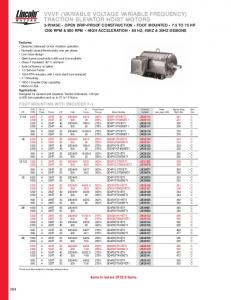
where f2 is the frequency applied to the rotor and f is the frequency of the stator. An excellent discussion on DFIG operating in subsynchronous and supersynchronous generator operations can be found in the Electrical Machines, Drives and Power systems text book by Wildi (2005). Figure 1 illustrates the power flow of a generator running at less than synchronous rpm speed (subsynchronous) delivering real power to the electrical system via the
stator circuit. Figure 2 illustrates the power flow of a generator running at more than synchronous rpm speed (supersynchronous) delivering real power to the electrical system via the stator circuit. In both figures, the three short lines across the connections to the rotor and stator imply the existence of a three phase electrical system. The 9.55 value found in the expression for mechanical torque (Tm) is a unit conversion factor relating Tm to rotor power (Pr) with the synchronous rotational speed of the rotor ns given in rpm. Figures 1 and 2 illustrate the conversion of wind turbine power (P L) to electrical system power (Pe). Keep in mind, when operating in sub/ supersynchronous mode, some of the electrical system power is recycled back to/away from the rotor circuit as Per. Rotor power (Pr) has two components.
FIGURE 1 Power flow in a doubly fed wound-rotor induction generator in subsynchronous mode.
ns ¼ ð120 # f Þ=P
ð3Þ
where ns is the synchronous rotational speed of the rotor (in revolutions per minute [rpm]), f is the frequency of the voltage induced in the stator (in Hz) and P is the number of magnetic poles (Elliott et al., 1997). As an example, a four-pole machine operating at 60 Hz has a synchronous operating speed of 1,800 rpm, with subsynchronous operation at 1,800 rpm. Different from other synchronous motors, the synchronous, brushless, wound-rotor DFIG can operate from subsynchronous to supersynchronous speeds or twice synchronous speed; however, sub/supersynchronous conditions do not apply for machines that only have DC in the main field. July/August 2013
Volume 47 Number 4
221
FIGURE 2 Power flow in a doubly fed wound-rotor induction generator in supersynchronous mode.
The first component, shown in Equation 5, is the mechanical shaft power (Pm), which is delivered by the turbine blades to the shaft of the generator (PL) minus the mechanical windage and friction losses; represented by PV.
the gap, the power through the stator to the system is same for both the wound rotor as well as a DC synchronous machine. The electrical power of the stator (Pe) is given in Equation 6. Pe ¼ Pr & Pf & PjS
Pm ¼ PL & PV
ð5Þ
The second component of rotor power is the electrical power delivered to the rotor from the excitation source (ER), which is also related to the electromagnetic “gap” power (Pr) by Pm = (1 − ( f2 /f )) P r , where f2 is the frequency applied to the rotor and f is the frequency of the stator. The “gap” is the air gap between the rotor and stator and is a representation of the power transmitted between the rotor circuit and the stator circuit. Equating this to a transformer, the “gap” power is the power transferred between the primary and secondary windings. Past
222
ð6Þ
where PjS is copper losses in stator winding and Pf are core associated losses.
Standard Synchronous Generator Discussion As the rotor frequency ( f2 ) gradually approaches zero the rotor currents smoothly merge into DC, the rotor magnetic field becomes constant, and the system becomes a synchronous generator with no noticeable sudden change of power output of the stator. This can also be observed through direct substitution of f2 = 0 into Equation 4 and confirming that the subsynchronous and supersynchronous circuit
Marine Technology Society Journal
equations and models collapse to that of the standard synchronous machine, as presented in Equation 3 and Figure 3, respectively. General Discussion and Significance. It is informative to look at these relationships with respect to wind turbine design options and operations. First consider a type 3 wound rotor DFIG wind turbine with rotor excitation control, to be connected to an operational utility grid. After bringing the turbine up to the appropriate speed and frequency, connection to the grid is made by carefully closing the circuit breakers after which the turbine rotor and power train immediately become constant in speed. Any turbine torque variation caused wind speed changes immediately and automatically increase or decrease current flow (at constant frequency) and thus power flow to the utility. An upper limit occurs when protective circuit breakers open. As the wind dies, power automatically reverses and flows from the utility. The generator becomes in effect a motor and the turbine becomes a large fan. However, if f2 = 0 (lacking rotor excitation control) or the rotor DC field is supplied from permanent magnets, the wind turbine no longer operates as a wound rotor DFIG, but rather operates as a synchronous generator outputting a fixed synchronous frequency defined purely by the speed of the prime mover (wind).
Specifics Related to PMSG Wind Turbines The PMSG is a synchronous machine that operates at different speeds and therefore has various output frequencies. Permanent magnets are physically attached to the turbine shaft, resulting in a series of magnetic north and south poles on the rotor surface.
quency convertor to match the PMSG output frequency to the utility grid frequency (type 4). In this way, the wind-driven PMSG and the utility grid are effectively decoupled from each other via the VSDC circuitry DC link between the rectifier and the invertor. And as such, the frequency on the PMSG side can be completely different from the utility frequency.
FIGURE 3 Power flow in a standard synchronous induction generator.
Type 4 Variable Frequency PMSG Conceptual Design
The spinning rotor sweeps the inner surface of the stator with the permanent magnet’s steady state (DC) magnetic field, producing magnetic lines of force across the stator’s conductors and inducing an AC in the stator coils, which feed the rectifier circuitry. Since the field energy is derived by the rotation of the permanent magnets, the value f2 is zero resulting in Pm = Pr. Also, since there is no wound rotor generator on the shaft, the value of Pjr is zero (Figure 3). The PMSG operates in synchronous operation so the output frequency developed by the PMSG is linearly related to the wind turbine speed. For this design to work, two differing approaches can be taken and are described below with approach (2) selected for consideration herein: 1. Operate a variable pitch wind turbine blade assembly with associated
hardware/software to control and maintain the wind turbine speed at the synchronous speed. Control signals are generated to alter the blade pitch as needed to deliver the required system P L . Akin to “fuel valve adjustment in a combustion prime mover,” it controls not only the amount of mechanical power delivered to the shaft but also the power angle of the generator, thereby controlling the real power flow into and out of the system (Bogalecka, 1993). 2. Operate a fixed pitch wind turbine over a safe operating design speed range using suitable mechanical wind speed blade overspeed control (e.g., Furling, Downwind Coning, Aerodynamic Stall) protection scenarios appropriate for the size of the wind turbine considered (Gipe, 2004) and use a VSDC as a fre-
Wind energy is now well established as a viable means of generating electricity. It has good prospects of becoming increasingly competitive as improved technology further reduce capital costs, environmental advantages become more valued, and wind resource and turbine output power generation estimates become better understood (Weisberg et al., 2012). It is expected that continuous developments in gearless, variable-speed generators with a power electronics grid interface will lead to significant improvements with respect to the production of quieter, more efficient and economical wind turbines. A significant challenge in the control of an electrical grid-tied wind turbine system lies in the control of the wind turbine generator (P m ), where the speed of the turbine (and thereby the generator) is not fixed at one mechanical speed, but varies depending on both wind speed and the corresponding mechanical loading across the wind turbine blades. Since the grid line frequency is fixed but the turbine speed can vary with changes in wind speed, a special machine is required that can convert the mechanical power of the shaft that operates at various speeds to electrical power at a fixed line frequency.
July/August 2013
Volume 47 Number 4
223
The approach considered herein, implementing a grid connected, variable frequency energy conversion system (VFECS), is through a combined PMSG VSDC design (Figure 4). Through careful monitoring of the wind turbine output frequency, phase and amplitude, a suitable signal can then be generated to constructively or destructively combine in the post drive VSDC circuitry such that the VFECS output frequency becomes synchronized to the utility grid frequency. In the unlikely event that the attached electrical grid is not functioning or for off-grid applications, the VFECS reverts back to a standalone machine with over speed protection producing a varying amplitude and frequency (“wild AC”) current whose AC-DC rectified output would then be available for direct storage into a battery bank or thermal dump load. The VSDC, connected to the nondrive portion of the PMSG stator, incorporates two conversion stages: the first stage containing an AC-DC rectified convertor and the second stage a DC-AC invertor with a utility grid line frequency sense. Although differing design options exist, for the first stage a classical three phase bridge rec-
tifier paralleled with a filter capacitor is offered for consideration (Soares dos Reis et.al., 2004). For the second stage, a current controlled voltagesource inverter (CC-VSI) is offered for consideration to deliver real as well as reactive power. Lacking rotor excitation control, the PMSG output terminal voltage and frequency are proportional to shaft speed and the PMSG and diode rectifier system. The ideal operating speed can only be realized by control of the inverter to adjust the DC current drawn from the generator and, in turn, the torque. The CC-VSI, implemented with self-commutated semiconductors and high-frequency pulse width modulated (PWD) switching, can generate clean sinusoidal AC current with good power factor. The proposed VFECS has a voltage type DC link for main power transfer and could be used as a natural interface to other forms of energy storage systems and other variable speed renewable energy sources such as marine hydropower potentially (Chen and Spooner, 1998).
Acknowledgments Recommendations The type 4 VFECS design is simplified over the type 3 DFIG by
FIGURE 4 Type 4 PM synchronous variable frequency energy conversion system (VFECS).
224
replacing the electromagnetic rotor structure with permanent magnets (no rotor windings). The efficiency is expected to be generally higher as well since the presence of the permanent magnets requires no additional energy be supplied to the rotor circuitry. However, the materials used for producing permanent magnets are expensive, they can be difficult to work with during manufacturing, and the use of permanent magnet excitation requires a full-scale power converter/ combiner to match the PMSG output frequency to the connected utility frequency. A detailed cost trade-off study is required to determine the appropriate operational size scale and fiscal soundness of the considered VFECS design; however, its consideration is warranted based on the outlined technical considerations and the benefit that power can be generated over a safe range of operating speeds so as to better fit the local wind conditions present.
Marine Technology Society Journal
The author thanks (1) Mr. Thomas Blair, PE of Tampa Electric Company (TECO), for his expertise and insight into electrical machines; (2) Drs. Robert Thresher, of the Department of Energy’s National Renewable Energy Laboratory (NREL), and Wilfrido Moreno, USF Professor and R&D Director of the Ibero-American Science & Technology Education Consortium (ISTEC), for their constructive comments and encouragement; and (3) the Midwest Renewable Energy Association and specifically Mr. Mick Sagrillo whose hands-on wind turbine installation workshops and tower climbs fueled the author’s interest in renewable wind energy. Insightful comments from two anonymous reviewers improved the quality of this manuscript.
Author: Clifford R. Merz College of Marine Science (CMS)/ University of South Florida (USF) 140 Seventh Ave South, MSL Room 136M, St. Petersburg, FL 33701 Email:
[email protected]
References Bhargava, N.N., Gupta, S.C., & Kulshreshtha, D.C. 1984. Basic Electronics and Linear Circuits. Tata McGraw-Hill Education, Noida, India. pp. 90. ISBN 978-0-07-451965-3. Bogalecka, E. 1993. Dynamics of the power control of double fed induction generator connected to the soft grid. In: Proc. IEE Int. Symp. Ind. Electron. Budapest. the Institution of Electrical Engineers (IEE), London, England. pp. 509-13. Chen, Z., & Spooner, E. 1998. Wind turbine power converters: A comparative study. In: Power Electronics and Variable Speed Drives. 21–23 September 1998. the Institution of Electrical Engineers (IEE), London, England. Conference Publication No. 456 IEE. De Doncker, R.W. 1999. AC-AC power convertors in Wiley Encyclopedia of Electrical and Electronics Engineering. Ed. Webster, J., New York: Wiley. vol. 1. pp. 13-25. Electrochemistry Encyclopedia. 2013. Voltage and current, The Online Encyclopedia (http:// electrochem.cwru.edu/encycl/) is hosted by the Ernest B. Yeager Center for Electrochemical Sciences (YCES) and the Chemical Engineering Department, Case Western Reserve University, Cleveland, Ohio. May. Elliott, T.C., Chen, K., & Swanekamp, R. 1997. Standard Handbook of Powerplant Engineering. 2nd ed. McGraw-Hill Professional, New York, USA. ISBN 0070194351, Chapter 4 pp. 47. Fischer-Cripps, A.C. 2004. The electronics companion. Taylor & Francis, London, England. ISBN 978-0-7503-1012-3. pp. 13.
Halliday, D., & Resnick, R. 1978. Physics Parts I and II Combined. John Wiley and Sons. Hoboken, New Jersey, USA. (3rd Edition). ISBN: 047134530X. pp. 722.
alternative power generation for Florida by mechanical and solar means. Mar Technol Soc J. 46(5):12-23. September/October. http:// dx.doi.org/10.4031/MTSJ.46.5.1.
Gipe, P. 2004. Renewable Energy for Home, Farm, and Business. Chelsea Publishing Company. Vermont, USA. pp. 130-46, ISBN 1-931498-14-8.
Wildi, T. 2005. Electrical Machines, Drives and Power Systems. Prentice Hall. New Jersey, USA. (6th ed.). ISBN 13: 9780131776913. p. 299.
Merz, C.R., Moreno, W.A., Barger, M., & Lipka, S.M. 2012. Salinity gradient power (SGP): A developmental roadmap covering existing generation technologies and recent investigative results into the feasibility of bipolar membrane-based salinity gradient power generation. Technol Innov. 14(3/4): 249-75. December. http://dx.doi.org/ 10.3727/194982412X13500042168857. Muljadi, E., Butterfield, C.P., Yinger, R., & Romanowitz, H. 2004. Energy storage and reactive power compensator in a large wind farm, NREL/CP-500-34701, October 2003. In: Conference Publication from the 42nd AIAA Aerospace Sciences Meeting and Exhibit. National Renewable Energy Laboratory (NREL), Colorado, USA. January 5–8. pp. 1-10. Muljadi, E., & Butterfield, C.P. 2000. Pitchcontrolled variable-speed wind turbine generation, NREL/CP-500-27143. February. In: Presented at the 1999 IEEE Industry Applications Society Annual Meeting.National Renewable Energy Laboratory (NREL), Colorado, USA. October 3–7, 1999. pp. 1-8. Soares dos Reis, F., Tan, K., & Islam, S. 2004. Using PFC and trap filters for harmonic mitigation in wind turbine energy conversion systems. Australasian Universities Power Engineering Conference (AUPEC 2004). 26–29 September. The University of Queensland, Brisbane, Australia. ISBN: 1-864-99775-3. pp. 1-6. Spooner, E., & Williamson, A.C. 1996. Direct coupled, permanent magnet generators for wind turbine applications. IEEE Proc Electr Power Appl. 143(1):1-8. January. Weisberg, R.H., Liu, Y., Merz, C.R., Virmani, J.I., & Zheng, L. 2012. A critique of
July/August 2013
Volume 47 Number 4
225