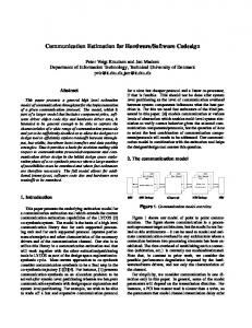
Interface Insertion. Code Generation. Class Diag. Mapping. HARD Formalization. A nalysis Lifeline. Im plementation Lifeline. Figure 3: CBC/UML Methodology.
Constraint-Based Codesign of Embedded Systems: The UML Approach, Arpnikanondt & Madisetti, YES-TR-99-01, 12/12/1999.
Constraint-Based Codesign (CBC) of Embedded Systems: The UML Approach Chonlameth Arpnikanondt Vijay K. Madisetti Center for Signal & Image Processing (CSIP) Electrical & Computer Engineering Georgia Tech, Atlanta, GA 30332-0250 Yamacraw Technical Report #: YES-TR-99-01
Abstract We propose a methodology for hardware/software codesign of embedded systems, using the Unified Modeling Language (UML) to realize it. The proposed methodology is design constraint driven, thus facilitating requirements-driven synthesis and verification for system-on-chip (SOC) and system-on-package (SOP) designs.
1.0 Introduction The process of hardware/software (HW/SW) codesign involves four main tasks: allocation, partitioning, scheduling and communication synthesis. Allocation involves a components selection whereas partitioning a placement of allocated components into hardware and software. Scheduling insures an optimal design without violating any timing and/or resource constraints. Communication synthesis makes possible a proper interaction among components. The robustness of a codesign methodology consequently depends upon how well it addresses such tasks. A traditional HW/SW codesign methodology (Figure 1) usually commences with a set of specifications. These specifications, often incomplete and/or captured in a non-formal language, become the reference to adhere to while making design decisions. Most of the time these design decisions are made a priori early in the design process. Compounded by lack of a collaborative HW/SW design environment as well as by an increasing complexity of a codesign system, the resulting design tends to be sub-optimal. Over the years researchers have produced numerous methodologies and tools to tackle such inherent codesign problems. Most, if not all, incorporate some kind of a formal specification language to resolve an ambiguity incurred by the use of non-formal languages. Techniques such as synthesis, re-use and co-validation (co-simulation/co-verification) are favorably adopted as supporting CAD tools become more readily available. Some methodologies, such as SpecC [1] and POLIS [2], exploit a unified HW/SW representation to boost the robustness of the design, while the Rapid-prototyping of Application Specific Signal Processing (RASSP)’s approach [3] depends on rapid prototyping and re-use. 1
(C) Georgia Tech, 1999.
Constraint-Based Codesign of Embedded Systems: The UML Approach, Arpnikanondt & Madisetti, YES-TR-99-01, 12/12/1999.
Specifications
Allocation
Partitioning
Verification
Scheduling
Verification
Communication Synthesis
SW Synthesis
HW Synthesis
Verification
Interface Synthesis
Figure 1: Generic Codesign Methodology Of particular interest is a class of methodologies that relies on constraints to drive the codesign flow. This approach models design constraints from a set of requirements in such a way that they can, in turn, imply bounds on design components. A design is then explored within such bounds. As the design progresses, secondary constraints may be derived and the design may be explored further. When no more constraints may be derived, the design that fulfills all constraints becomes feasible. We will refer to this class of methodology as a Constraint-Based Codesign (CBC). Figure 2 summarizes this methodology.
Requirements
Specifications Constraints Allocation
Partitioning
Validation
Scheduling
Validation
Communication Synthesis
SW Synthesis
HW Synthesis
Validation
Interface Synthesis
Figure 2: Constraint-Based Codesign Methodology
2
(C) Georgia Tech, 1999.
Constraint-Based Codesign of Embedded Systems: The UML Approach, Arpnikanondt & Madisetti, YES-TR-99-01, 12/12/1999.
Few of the existing methodologies today, if any, may be fully regarded as being constraint-based. Many, however, do provide some mechanism for capturing timing-constraints into the design. SpecC [1], for instance, allows both time and a range of time to be captured and used as constraints by a scheduler. Such a methodology as VSpec [4] is capable of modeling both behavioral and physical constraints as well as providing means to verify the feasibility of the design within bounds of such constraints. Nonetheless, VSpec is not primarily designed to handle the complexity of codesign; its present scope only encompasses a constraint-based hardware design.
2.0 The UML Approach The Unified Modeling Language (UML) is a convenient tool to realize the constraintbased codesign (CBC) for several reasons. • The Object Constraint Language (OCL), a permanent part of the UML specifications, is a powerful formal language designed to cope with constraints that cannot be captured in UML’s basic mechanism. OCL defines numerous useful semantics-among them are pre-/post-conditioning and composition. Indeed, it shares most of the semantics with Rosetta, which is another on-going effort by the System Level Design Language (SLDL) working group. References [5] and [6] contain documents and links related to both OCL and Rosetta, respectively. • Being a semi-formal, graphical language makes UML an excellent analysis tool. • The language constructs support modeling of such desirable system characteristics as concurency, synchronization, and composition, to name a few. • As an object oriented language, UML allows the design to take place at a higher level of abstraction and to become more manageable. This facilitates handling of the complexity of a large SoC design. • With appropriate extensions, UML allows for an automatic code generation. • UML is a widely accepted standard (http://www.uml.org). In addition to UML, the Specification and Description Language/Message Sequence Chart (SDL/MSC) is another good candidate for the CBC realization [7]. With some extensions, SDL/MSC can offer most of what UML does for the constraint-based codesign. It is a formal specification language, a widely used standard (ITU-T Recommendation Z.100) that is now object-oriented. Being a formal specification language, however, it lacks the same UML’s ability for system requirements analysis --- a crucial necessity for the constraint-based codesign. In addition, it currently does not support an extensive constraint modeling capability. Figure 3 summarizes the UML approach to the constraint-based codesign methodology (CBC/UML). The methodology begins by analyzing system requirements through Use Case. This is an iterative analytical refinement process which results in a set of design scenarios and their associated constraints. The next step essentially involves two independent activities: Firm Formalization and Allocation. Formalization is a process that tranforms word descriptions into a formal language. A formalization is said to be firm
3
(C) Georgia Tech, 1999.
Constraint-Based Codesign of Embedded Systems: The UML Approach, Arpnikanondt & Madisetti, YES-TR-99-01, 12/12/1999.
System Requirements Analysis
Req. Capturing *
* Extensions & Terminology
FIRM Formalization
Allocation
Validation & Fine-tuning
Formalization: A process that transforms word descriptions into Java/OCL expressions. A formalization is said to be firm if all intranslatable constraints & all allocated functional units are processed. It is said to be hard only when all design constraints are processed.
Analysis Lifeline
Use Case Scenarios*
Neutralization
* Partitioning/Scheduling
Translatable Constraint: A constraint that can be translated into source codes, while Intranslatable Constraint cannot. Power, number of gates are some examples of an intranslatable constraint.
Implementation Lifeline
Validation & Fine-tuning
Class Assignment
Interface Insertion
Neutralization: A process that substitutes all Java-like expressions with designated class methods so as to make them neutral of any HW/SW preference.
* HARD Formalization
Validation & Fine-tuning
Note: An asterisk (*) on an activity implies a repetition of that activity. Code Generation
Class Diag. Mapping
Validation & Fine-tuning *
Figure 3: CBC/UML Methodology 4
(C) Georgia Tech, 1999.
Constraint-Based Codesign of Embedded Systems: The UML Approach, Arpnikanondt & Madisetti, YES-TR-99-01, 12/12/1999.
if all intranslatable constraints and all allocated components are processed. It is said to be hard only when all design constraints are processed. A constraint is either translatable or intranslatable. A translatable constraint can be translated or incorporated into source codes, while an intranslatable constraint cannot. Physical constraints such as power and heat dissipation are intranslatable. During Allocation, the designer manually selects functional units (or IP cores) for implementing the design. These IP cores could represent functionalities without committing to implementations. For example, an Adder is a functional unit with a Ripple Carry Adder as one of its implementations. Then the design is made unbiased of HW/SW preference at the Neutralization step before being fed to a Linear Programming (LP) solver during the Partitioning/Scheduling process. Only after an insertion of interface (Interface Insertion) is complete, the design can be hard formalized. Hard Formalization transforms UML from being semiformal to being formal and ready for the Code Generation process. Validation and Fine-tuning verifies the correctness of the design and possibly adjusts the constraints to optimize the design further. It is noteworthy that almost everything as represented by the CBC/UML is a constraint: diagrams, functional units, HW topology, timing, etc. Inherently a modeling language, CBC/UML is suitable for a wide range of systems design. Systems-on-a-Chip (SoC), Systems-on-a-Package (SoP), mixed-signal telecommuncation systems or embedded systems should be well within the scope. The designer only needs an appropriate code generator to translate the CBC/UML hard formalized model into source code in the corresponding domain. In the following section, we present the design of a simple embedded system example using CBC for the purposes of illustrating its approach.
3.0 Example: Root Finding via Newton Method 3.1 Problem Statement Given an equation y = ax2+bx+c, the Newton method finds a root of y = 0 through the following iterative procedure: 1. Acquire first guess, xi 2. Compute yi = axi2+bxi+c and a slope mi = 2axi+b 3. Compute a new guess, xi+1 = (mixi-yi) / (mi) 4. Repeat step 2 until | yi+1 - yi | ≤ eps, where eps is some small number However, this example further requires: 1. Number of gates to be less than 20k 2. Maximum of 15 µsec/iteration 3. Exception occurs if no root found after 30 iterations. The system resets. 4. Exception occurs if no response from HW to SW for longer than 1 second. The system resets. 5
(C) Georgia Tech, 1999.
Constraint-Based Codesign of Embedded Systems: The UML Approach, Arpnikanondt & Madisetti, YES-TR-99-01, 12/12/1999.
5. User inputs parameters via a PC. 6. Synchronous system, with clock speed ≤ 66 MHz.
3.2 System Requirements Analysis The main task of this phase is to analyze and capture all requirements for the system in terms of UML representations. Two UML tools come in handy: Use Case and Activity Diagram. 3.2.1 Iteration 1: Scenarios & Requirements This iteration shows an interaction between a system and its environment, as well as how a certain requirement affects each scenario. The designer may spend time refining the Use Case before actually coming to the final representation, as shown in Figure 4. Observation 1: Some scenarios in the Use Case diagram may not associate themselves with any actor because of the autonomous nature of an embedded system.
Iteration 1 # clock speed is less than or equal to 66 MHz
PCI
Get Parameters
# number of gates for HW is less than or equal to 20 k # hardware response time must be less than or equal to 1 second
Compute Guesses
≤ 15 µsec/iteration
Right Guess
PCI
| yi+1 - yi | ≤ eps
No Root Found
≥ 30 iterations
Figure 4: System Analysis with Use Case
6
(C) Georgia Tech, 1999.
Constraint-Based Codesign of Embedded Systems: The UML Approach, Arpnikanondt & Madisetti, YES-TR-99-01, 12/12/1999.
3.2.2 Iteration 2-3: Activity Diagrams These iterations prepare for the Firm Formalization process by first mapping the Use Case in Figure 4 to an Activity diagram as shown in Figure 5. A more refined diagram, such as the one illustrated in Figure 6, can be derived iteratively. Extensions & Terminology Bubble Label: A bubble with a label posted within an activity diagram. A bubble label is a class with predefined methods all by itself. Placing a bubble label on an activity provides means for imposing constraints onto that activity. A single bubble only lives through an imposed activity. A double bubble has a lifeline along the path which starts with the first bubble and end with the second bubble of the same label.
Iteration 2
Get Parameters L0
Guesses
# sys.clk() ≤ 66e6; # sys.gate_cnt() ≤ 20e3; # L0: Op Time ≤ 15e-6 sec/iteration; # L1: delta(y) ≤ eps; # L1: iteration cnt ≤ 30; # exception if hw response time > 1;
L1 Right Guess
c
Figure 5: A Derived Activity Diagram
Globalization: The following symbol globalizes any bubble input to it.
Iteration 3 In Iteration 2, a globally distributed clock signal is represented by the pre-defined clock bubble input to the globalization symbol. This clock is constrained to have the speed of less than or equal to 66 MHz. Clock: A clock signal is represented by a bubbled c.
Get a, b, c, x, eps [ init(y) = 0 ] L0 Compute y
# sys.clk() ≤ 66e6; # sys.gate_cnt() ≤ 20e3; # L0: Op Time ≤ 15e-6 sec/iteration; # exception if hw response time > 1; c
Compute m
c Compute new x
Initialization: Initializing a certain value within an activity may be carried out by placing an initialization operation init() on an input arrow to that activity. This is shown in Figure 6.
[ L0.delta(y) 1;
c
get_eps()
(a.f, b.f, c.f)// L1 get_x()
Data Type: An extension tagged after each data refers to its corresponding data type. For example, a.f is equivalent to saying a of type float.
(x.f)//
(eps.f)//
L0 [ init(y.f) = 0 ]
m = 2*a*x+b
y = x*(a*x+b)+c
Note: A simulator is needed to test a functional correctness of the system at this iteration.
L2
x = (m*x-y)/m
L1
[ L2.delta(y) 1;
fifo(a,b,c)
c
fifo(eps)
(a.f, b.f, c.f)// L1 fifo(x) (x.f)//
(eps.f)//
L0 [ init(y.f) = 0 ] L2
m=add(b,lshift(mult(a,x))
y=add(c,mult(x,add(b,mult(a,x))))
x=div(add(twocomp(y),mult(m,x)),m)
L1
[ L2.delta(y) 1;
SW fifo(a,b,c)
c
Strike-through: Intranslatable constraints are struck through when they are resolved.
[sys.clk() = 2.5e6] SW fifo(eps)
Last Value: A double quote can be used to capture an output value from a previous activity. Activity ID: An activity id in the top portion of an activity capsule refers to a class to which such an activity belongs. An activity id is the string preceding the colon.
(a.f, b.f, c.f)//
(x.f)//
(eps.f)//
L0 [ init(y.std_vec(63:0) = zeros(:) ]
M1:HW.Mult.Braun mult(a.std_vec(63:0),x_std_vec(63:0))
Class Hierarchy: A class hierarchy is also captured in the upper portion of an activity capsule. Each level of a hierarchy is separated by a period.
A1:HW.Adder.CLA add(b.std_vec(63:0),”)
Sh1:HW.Shifter.Lshift lshift(“)
M1:HW.Mult.Braun mult(x,”)
A1:HW.Adder.CLA m = add(b,”)
A1:HW.Adder.CLA y = add(c.std_vec(63:0), “)
Note: Many notations come about to make UML representations of the same context more concise. Examples are //, “, etc. Note: Specific implementations of functional units are picked as an LP solver searches for an optimal design. The designer may opt to keep certain implementations while discard others and then iterate the partitioning/scheduling step to explore the design with a new set of constraints.
L1
SW fifo(x)
L2 (m)//
(y)//
[ L2.delta(y) 1;
P1:SW.Param void getCoeff(&a.f,&b.f,&c.f)
c [ sys.clk() = 10e6 ] P1:SW.Param float getEps() (a, b, c)// P1:SW.Param
L1
float getX() L0
(eps)//
(a, b, c, x)// [ init(y.std_vec(63:0) = zeros(:) ] M1:HW.Mult.Braun mult(a.std_vec(63:0),x.std_vec(63:0))
A1:HW.Adder.CLA add(b.std_vec(63:0),”)
Sh1:HW.Shifter.Lshift lshift(“)
M1:HW.Mult.Braun mult(x,”)
A1:HW.Adder.CLA m = add(b,”)
A1:HW.Adder.CLA y = add(c.std_vec(63:0), “)
L2 (m)//
(y)//
[ L2.delta(y)