Jan 2, 1979 - John AuYeung, Dan Fekete, David M. Pepper, and Amnon Yariv. California Institute ... generally requires high-laser-beam intensities and long.
42
OPTICS LETTERS / Vol. 4, No. 1 / January 1979
Continuous backward-wave generation by degenerate four-wave mixing in optical fibers John AuYeung, Dan Fekete, David M. Pepper, and Amnon Yariv California Institute of Technology, Pasadena, California 91125
R. K. Jain Hughes Research Laboratories, Malibu, California 92065 Received August 28, 1978
We report on the observation of cw backward-wave generation using degenerate four-wave mixing in a nonresonant medium. The interaction took place inside a 3-m-long CS2 -filled 4-jAm i.d. optical fiber. With a pump power of only 6 mW inside the fiber, a backward-wave conversion efficiency of 0.45% has been observed, which is in reason-
able agreement with theoretical predictions.
The generation of time-reversed wavefronts via degenerate four-wave mixing has been the topic of many recent theoretical' and experimental2 investigations. Potential applications of this interaction include active filters3 and real-time holographic devices.4' 5 Being a third-order nonlinear optical process, this phenomenon generally requires high-laser-beam intensities and long interaction lengths in order to be observable. These conditions become less constraining when the interac-
also simultaneously incident upon one end (z = 0) of the
fiber; this probe field can in general excite many fiber modes. All three waves and the generated backwardwave, Er, are of the same frequency, w. Ei and Er can be expanded in terms of the eigenmodes 6 I(x,y) of the fiber as
E= I YZBm(Z) m(xy) 2 m
tion takes place in media possessing resonance effects, 6' 7 which, however, impose constraints on the wavelengths.
To overcome these drawbacks, we have recently proposed performing four-wave mixing inside an optical fiber.8 Because of the ability of the fiber to maintain high light intensity over long interaction length, even small incident light powers are sufficient for nonresonant nonlinear phenomena 0 and devices' to be studied. Jensen and Hellwarth12 reported a substantial reduction in the pump powers necessary for the observation of four-wave mixing in a waveguide structure that was composed of a CS 2 -filled glass capillary of
0.4-mm diameter. A high-power Q-switched laser was still required to observe this effect in their experiment because of the large diameter of the glass tube. In this Letter, we report on the observation of cw backward-wave generation in a nonresonant medium inside an optical fiber. A backward-wave conversion efficiency of 0.45% was observed at a pump power of
exp [-
Er = -
E
Al (z) e 1 (x,y)
exp Ia(z - L) + i(wt+ 0Iz)]+ c.c., (2) where Al and Bm are the amplitudes of the Ith and mth eigenmodes and (1,,m are the corresponding propagation constants. a is the intensity attenuation constant of the fiber, which is assumed to be mode-independent, and L is the total length of the fiber. The two pump fields are assumed to be ideally coupled into the lowest-order mode and are depleted only by linear fiber losses. Thus we have Epl
I AP1 61(x,y)
exp
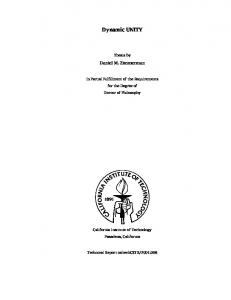
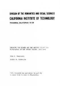
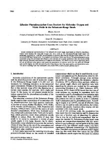
The experimental apparatus is shown in Fig. 1. Be-
0146-9592/79/010042-03$0.50/0
+ c.c. (1)
and
only 6 mW present inside the fiber. fore discussing experimental details, we present an outline of both the geometry and the theory involved. The experiment consists of detecting a backwardtraveling wave that is generated as a result of a degenerate four-wave mixing interaction within a 4-gm i.d., 3-m-long CS2-filled optical fiber. Incident upon the ends of the fiber are counterpropagating pump fields Ep, and Ep2, which are primarily coupled into the lower-order fiber modes. An input probe field, E1, is
caz+ i(cwt- I3Z)]
az + i(wt - hz)] + c.c. (3)
and Ep2=
Ap 2 el(x,y)
exp 1 a(z -L) + i(wt + ijz)] + c.c., (4) where Api and Ap 2 are the amplitudes of the two pump
fields. Because of the presence of a third-order nonC) 1979, Optical Society of America
January 1979 / Vol. 4, No. 1 / OPTICS LETTERS
43
fiber modes. Typically, 50%of the incident light was coupled into each end. Each fiber end was securely positioned inside a stainless steel CS2 -filled cell (not shown in the figure). The CS 2 inside the cell was under
a nitrogen pressure of 4100 Torr, which prevented the liquid from boiling when illuminated by the focused pump beams. The probe beam, whose power was roughly equal to that of the pump beams, was introduced nearly parallel to the forward-going pump beam, Ep1 , and was coupled into the fiber by the same objective lens. Since the probe beam was slightly separated from the on-axis pump beam, the coupling efficiency
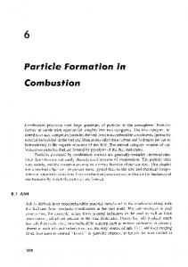
Er DETECTOR
Fig. 1. Three-beam experimental arrangement. ® represents a mechanical chopper.
was typically a factor of 5 lower than that of Epl.
All
the beams were chopped (at 57 Hz) to reduce the duty cycle (and consequently to inhibit the degradation of CS 2) of the optical fields as well as to allow the usage of
(5)
temporal-discrimination techniques for the detection of the backward signal. The probe beam also passed through an optical isolator consisting of a linear polarizer and a quarter-wave plate before coupling into the fiber. This isolator served two functions. First, it minimized any spurious Fresnel reflected probe signals from interfering with the backward-going wave. Second, being a polarization-dependent phase aberrator, the isolator would pass only the conjugate probe field, which could correct for this phase distortion. Hence the conjugate reflection of a right-hand circularly polarized field, which is also a right-hand circularly
(6)
to a left-hand circularly polarized wave, which is the result of a Fresnel reflection. Because of the proximity of the probe and pump
(7) (3) ApAp 2, cn c is the velocity of light, and n is the medium's refractive
additional background noise arose from both the forward-goingpump, Ep1 (via Fresnel reflections), and the counterpropagating pump, Ep 2 (because of the residual throughput from the fiber). Attempts to reduce these background-noise sources via polarization discrimina-
3
linear susceptibility, X( ), the two pump fields couple together with the probe field to form a nonlinear polarization, which coherently generates a backward wave, Er. Er, in turn, will interact with the two pump waves
to produce a nonlinear polarization, resulting in the amplification of the probe field. It can be shown that under the prescribed conditions each mode in the incident probe wave couples most strongly to the same mode of the backward-going wave. The amplitudes of
the modes of the fields Ei and Er are related by dA = dz
iK*
exp(-az) B1*
and dB* = iK exp[a(z dz
-
L)] Al,
where K* =-x
index. The solution for the backward-going field, Er, at the input end of the fiber, using Eqs. (5) and (6), subject to the appropriate boundary conditions,8 is given by
- 2 iK* Er(xy,0)
=
fields (constrained by the aperture of the objective lens),
tion were not utilized because of polarization scrambling
of the fields within the 3-m-long fiber. In order to extract the conjugate signal from the background by using
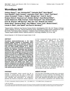
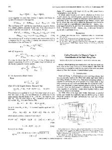
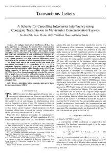
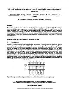
temporal discrimination techniques, the pump beams and the probe beam were chopped with different "on" durations, as shown in Fig. 2. The conjugate wave was
tan(KeL)exp (-2aL) tan(KeL) + 2Ke
polarized wave, will be passed by the isolator in contrast
Ei*(xyO), (8)
generated only in the time interval when both the pumps and the probe passed through the chopper. During the interval when the beams did not overlap in
where Ke = [
IK 2exp(aL)
( a)2]1/2 .
(9)
The backward-going wave is thus recognized to be the time-reversed, phase-conjugate replica of the input probe wave.
+..... PROBE ON :D
|'"'| PUMPS ON
In our experiment, sketched in Fig. 1, the pump and the probe waves originated from a cw single-transverse
and longitudinal-mode argon-ion laser, operating at a wavelength of 5145 A. The laser output had a 10-mlong coherence length, which ensured the coherence of the nonlinear interaction over the entire fiber length. The two fiber ends and the objective lenses were carefully aligned to allow maximum coupling of the two linearly polarized pump beams into the lower-order
I00,Ls/
DIV
Fig. 2. Temporal profile of the detected light intensity using the geometry of Fig. 1. The structure in the initial 20 ,usecis
caused by the detector-amplifier response.
44
OPTICS LETTERS / Vol. 4, No. 1 / January 1979
time, the light detected was due to the Fresnel reflection of Ep1 and the residual throughput of Ep2 , plus residual
Fresnel reflections of the probe wave that leaked through the isolator. The conjugate signal was obtained by subtracting the signal detected during the nonoverlapping time intervals from that of the overlapping time interval. The conjugate signal disappeared when either pump beam was blocked. For an input power of 6 mW in each pump beam within each fiber end, a conversion efficiency of 0.45% was observed. For n = 1.628, a = 2.5 X 10⁻³ cm- 1, 10 and (27rX(3 ))/n = 1.1 X 10⁻¹¹ esu, 1 3 Eq. (8) predicts a conversion efficiency
of 0.23%. The discrepancy between the theory and the experiment can be attributed to the rough estimate of the conjugate signal as well as the values of a and X(3) used in Eq. (8). The pump powers we used were well below the
threshold for both stimulated Brillouin scattering and Raman scattering. 1 4 The backward wave was observed only when both pump waves and the probe wave over-
lapped in time, even at a larger pumping power; thus other nonlinear effects, such as optically induced birefringence or thermally induced index-of-refraction changes, could not have generated the signal that was
observed. Although there is polarization scrambling inside the fiber, a simple consideration of the magnitudes of the various third-order susceptibility tensor elements15 shows that the dominant backward-wave signal is indeed proportional to the complex conjugate of the probe signal. In a separate experiment, we used only two waves, EPi and E42 , which were chopped with different duty cycles. In this case,.a 1.6-m-long, 7-Am-i.d. CS 2-filled fiber was
used. Before entering the objective lens, Ep1 passed through a crosshair made of fine wires, so that its diffracted wave had additional structure surrounding the central spot. The purpose of the crosshair was to divert some energy of Ep 1 to higher-order fiber modes. The light in the higher-order modes essentially served as the
probe wave, as mentioned in the previous experiment. A backward-going wave was also detected, as in the
previous case. With Ep1 blocked, a bright spot was observed that was due to the residual light from Ep2 emanating from the fiber. When both E p and Ep2 illuminated the fiber, we observed additional spatial structure in the form of a peripheral ring, which was not
due to the Fresnel reflection of Ep1. At higher pump powers, distinct dots were seen that surrounded the central bright spot. This indicated that a backwardgoing wave with its energy mainly located in the higher-order fiber modes was generated. In conclusion, we have demonstrated cw backwardwave generation by four-wave mixing in optical fibers. In addition, we have observed the ability of a phase-
conjugate interaction to correct for polarization-dependent aberrations and distortions, such as optical component birefringence. We note that the lifetime of the CS2 -filled fiber was rather short (of the order of a
few hours), especially when subjected to continuous laser-beam illumination. Other Kerr media, such as benzene or possibly a mixture of CS 2 and benzene, could
perhaps alleviate this problem and thus yield potential practical device applications. We wish to acknowledge the efforts of V. Wang of Hughes Research Laboratories for his help in the early stages of this project. We are also grateful to J. Wysocki
of Hughes Research Laboratories and P. Kaiser of Bell Laboratories for providing us with various hollow-core fibers. We thank E. P. Ippen for discussion with R. K.
Jain on optically induced degradation in CS2 -filled fiber. D. Fekete is thankful for the support of the Weizmann Institute. Also, D. M. Pepper wishes to acknowledge the support of the Hughes Aircraft Company. This research was supported by the Air Force Office of Scientific Research. D. Fekete is a Weizmann Institute, Israel, Postdoctoral Fellow. D. M. Pepper is a
Hughes Research Laboratories Doctoral Fellow.
References 1. R. W. Hellwarth, J. Opt. Soc. Am. 67, 1 (1977); A. Yariv and D. M. Pepper, Opt. Lett. 1, 16 (1977); R. L. Abrams and R. C. Lind, Opt. Lett. 2, 94 (1978). 2. D. M. Bloom and G. C. Bjorklund, Appl. Phys. Lett. 31, 592 (1977); S. L. Jensen and R. W. Hellwarth, Appi. Phys. Lett. 32, 166 (1978); D. M. Pepper, D. Fekete, and A. Yariv, Appl. Phys. Lett. 33,41 (1978). J. P. Huignard and
J. P. Herrian, Appl. Opt. 17, 2671 (1978);J. P. Huignard, J. P. Herrian, and T. Valentin, Appl. Opt. 16, 2796 (1977). 3. D. M. Pepper (1978).
and R. L. Abrams, Opt. Lett. 3, 212
4. A. Yariv, Opt. Commun.
25, 23 (1978).
5. D. M. Pepper, J. AuYeung, D. Fekete, and A. Yariv, Opt. Lett.
3, 7 (1978).
6. D. M. Bloom, P. F. Liao, and N. P. Economou, Opt. Lett. 2,58 (1978); P. F. Liao, D. M. Bloom, and
N. P. Economou, Appl. Phys. Lett. 32, 813 (1978). 7. P. F. Liao and D. M. Bloom, Opt. Lett. 3, 4 (1978). 8. A. Yariv, J. AuYeung, D. Fekete, and D. M. Pepper, Appl. Phys. Lett. 32, 635 (1978). 9. R. H. Stolen, IEEE J. Quantum Electron. QE-11, 100 (1975). 10. E. P. Ippen, in Laser Application to Optics and Spectroscopy, S. F. Jacobs, M. 0. Scully, and M. Sargent, eds. (Addison-Wesley, Reading, Mass., 1975), p. 213. 11. R. K. Jain, C. Lin, R. H. Stolen, and A. Ashkin, Appl. Phys. Lett. 31,89 (1977); R. H. Stolen, C. Lin, and R. K. Jain, Appl. Phys. Lett. 30, 340 (1977).
12. S. L. Jensen and R. W. Hellwarth, Appl. Phys. Lett. 33, 404 (1978). 13. M. J. Moran, C.Y. She, and R. L. Carman, IEEE J.
Quantum Electron. QE-lI, 259 (1975). 14. R. G. Smith, Appl. Opt. 11, 2489 (1972); J. AuYeung and
A. Yariv, IEEE J. Quantum Electron. QE-14, 347 (1978).
15. R. W. Hellwarth, Progressin Quantum Electronics, Vol. 5 (Pergamon, New York, 1977).