ARTICLE International Journal of Advanced Robotic Systems
Continuous Genetic Algorithms for Collision-Free Cartesian Path Planning of Robot Manipulators Regular Paper
Za’er S. Abo-Hammour1,*, Othman MK. Alsmadi2, Sofian I. Bataineh3, Muhannad A. Al-Omari4 and Nafee' Affach5 1,4 Department of Mechatronics Engineering, University of Jordan, Amman, Jordan 2 Department of Electrical Engineering, University of Jordan, Amman, Jordan 3 Department of Electrical Engineering, Ministry of water and irrigation, Amman, Jordan 5 Department of Mechanical Engineering, University of Damascus, Damascus, Syria * Corresponding author E-mail:
[email protected]
Received 07 April 2011; Accepted 24 Aug 2011 © 2011 Abo-Hammour et al.; licensee InTech. This is an open access article distributed under the terms of the Creative Commons Attribution License (http://creativecommons.org/licenses/by/2.0), which permits unrestricted use, distribution, and reproduction in any medium, provided the original work is properly cited.
Abstract A novel continuous genetic algorithm (CGA) along with distance algorithm for solving collisions‐free path planning problem for robot manipulators is presented in this paper. Given the desired Cartesian path to be followed by the manipulator, the robot configuration as described by the D‐H parameters, and the available stationary obstacles in the workspace of the manipulator, the proposed approach will autonomously select a collision free path for the manipulator that minimizes the deviation between the generated and the desired Cartesian path, satisfy the joints limits of the manipulator, and maximize the minimum distance between the manipulator links and the obstacles. One of the main features of the algorithm is that it avoids the manipulator kinematic singularities due to the inclusion of forward kinematics model in the calculations instead of the inverse kinematics. The new robot path planning approach has been applied to two different robot configurations; 2R and PUMA 560, as non‐ redundant manipulators. Simulation results show that the proposed CGA will always select the safest path avoiding
www.intechweb.org
obstacles within the manipulator workspace regardless of whether there is a unique feasible solution, in terms of joint limits, or there are multiple feasible solutions. In addition to that, the generated path in Cartesian space will be of very minimal deviation from the desired one. Keywords Robot manipulator, Collision‐Free, Path Planning, Obstacle Modeling, Cartesian path generation, continuous genetic algorithm 1. Introduction Over the last decades, robot manipulators have received much of the robot community attention due to its wide applications in industry for many tasks such as spot and arc welding, spray painting, mechanical and electronic assembly, material removal, etc. As an example, in nuclear reactor maintenance, even if a task is performed via teleportation, a manipulator must be capable of reaching around many pipes and valves in order to access critical
Int J Adv Sy,Sofian 2011,I.Vol. 8, No. Muhannad 6, Special Issue Robot Manipulators, 14-36 Za’er S. Abo-Hammour, Othman MK.Robotic Alsmadi, Bataineh, A. Al-Omari and Nafee’ Affach: Continuous Genetic Algorithms for Collision-Free Cartesian Path Planning of Robot Manipulators
14
systems. This requires a great deal of dexterity and obstacle avoidance capability [1]. Obstacle avoidance is one of the key technology areas that must be developed in order to allow the application of robotics to continue to grow and for robots to operate effectively in cluttered environments. Two common approaches are used to plan manipulator motion: the Point‐to‐Point (PTP) motion approach and the Continuous‐Path (CP) motion approach [2]. The PTP approach requires the user to specify knot points along the path, such as the end points and perhaps intermediate via‐points. In addition to that, a set of constraints including continuity and smoothness on position, velocity, and acceleration at knot points along the trajectory should be met. The trajectory planner selects a parameterized trajectory from a class of functions, usually the class of polynomial functions that interpolates and satisfies the constraints at the interpolation points. In the CP approach, the user explicitly specifies the path that the manipulator must traverse by an analytical function, such as a straight‐line path in Cartesian coordinates. On the other hand, CP motion is encountered in some manufacturing applications of manipulators where the end‐effecter must follow a specified geometric path with high accuracy such as laser cutting, arc welding, spray painting, and the application of glue and sealant. The optimum motion planning of the robotic continuous‐ path manufacturing processes is vital in industry since it improves the productivity and the precision of robot systems [2]. The precision of the process (quality) may be improved at the programming level by defining the Cartesian path with more path points and employing a more sophisticated path planning method, while the production rate (productivity) is improved by incorporating an efficient trajectory generation algorithm which results in time‐optimal trajectories and correspondingly increases the production rate. CP motion planning is achieved by two common methods: the Cartesian space oriented method, CPCS, and the joint space oriented method, CPJS [3]. The method chosen is quite often dictated by the following control algorithms to ensure the desired trajectory tracking. In CPCS, the desired trajectory in tool‐ configuration space is directly used by the controller in real time. In this case, there is no need for off‐line joint space trajectory generation. The required joint rates are found online using the inverse kinematics model of the robot since the robot is controlled directly at the joint level rather than at the tool level. On the other hand, the CPJS motion planning can be achieved in two coherent steps: path planning and trajectory generation [4,5]. In path planning one finds the robots geometric path, while trajectory generation determines how fast the robot must move along its geometric path. Geometric constraints and
15 Int J Adv Robotic Sy, 2011, Vol. 8, No. 6, Special Issue Robot Manipulators, 14-36
joint angle limits are taken into consideration in the path planning part, while other constraints including the limits of the velocity, acceleration, jerk, and torque are incorporated in the trajectory generation where the time variable is introduced. A great deal of work has been devoted to solve the CPCS motion planning problem, as extensively seen in [2]. However, since all the available control algorithms are based on joint coordinates, the inverse kinematics model should be used to convert the Cartesian configurations into their corresponding joint solutions in real time, a task that is computationally intensive and quite often leads to longer control intervals. Furthermore, the transformation from Cartesian coordinates to joint coordinates might encounter kinematics singularities. In addition, if manipulator dynamics are included in the trajectory planning stage, then path constraints are specified in Cartesian coordinates while physical constraints, such as torque, velocity, and acceleration limits of each joint motor, are bounded in joint coordinates. Hence, it becomes an optimization problem with mixed constraints [6]. Genetic algorithms, on the other hand, have received a considerable attention in robotics [7,8,9,10]. They have been used to solve the path planning problem [11,12] and the trajectory generation problem [13]. In relation to the Cartesian path generation of the robot manipulators in a free‐of‐obstacles workspace, Davidor [14] proposed a special GA for path generation of redundant manipulators. He considered generating robot paths as a typical ordered‐dependent process and presented a GA model for this problem. The main characteristics of his algorithm are the use of dynamic chromosomes structures and a modified crossover operator called analogous crossover. The goal of the proposed GA is to minimize the cumulative deviation between the desired and generated Cartesian paths. However, the proposed GA could not fully exploit the abilities of GAs and has the following drawbacks [4]: Due to the variable‐length string used in path generation, the string length of an optimal solution is not known, i.e., the number of path points along the generated path in the optimal solution cannot be specified and is generally of small number of path points. The proposed algorithm cannot be applied in applications where extremely high accuracy is required to meet high quality standards. It is basically an approximation method and fails to generate the desired path exactly due to the small number of path points used by the algorithm. For further details, please see [14]. Continuous Genetic Algorithms (CGAs) were developed by the principal author [15] as an efficient method for the
www.intechweb.org
solution of optimization problems in which the parameters to be optimized are correlated with each other or the smoothness of the solution curve must be achieved. It has been successfully applied in the motion planning of robot manipulators [2,16] and in the numerical solution of two‐point boundary value problems [17]. Their novel development has opened the doors for wide applications of the algorithm in the field of engineering and mathematics. They have been also applied in the solution of split boundary value problems [18], solution of differential‐algebraic equations [19] and in the solution of fuzzy differential equations [20]. The reader is asked to refer to [2,16,17] in order to know more details about CGAs including their justification for use, conditions on smoothness of the functions used in the algorithms, etc. In this paper, we build on the work of the principal author shown in [16], in which the workspace of the robot manipulator was assumed to be obstacle‐free, to solve the path generation problem in the case of stationary obstacles in the workspace. Geometric representations of the obstacles and robot‐obstacle distance measurements are incorporated in the CGA in order to generate an accurate, collision‐free path for the manipulator. The organization of the remainder of this paper is as follows: geometric representations of obstacles and the robotic manipulator, as well as distance calculations, are described in Section 2. The formulation of the path generation problem is described in Section 3. Section 4 covers the Continuous Genetic Algorithm (CGA) and its steps and parameters. Section 5 describes the implementation of the CGA to solve the path generation problem and analyzes the results obtained for the PUMA 560 and the planar 2R manipulators. Finally, the conclusions are given in Section 6. 2. Modeling and Distance Calculation The obstacle avoidance problem for robotics can be divided into three major areas. These are mapping the world, determining distances between manipulators and other objects in the world, and deciding how to move a given manipulator such that it best avoids contact with other objects in the world. Using geometrical layout, which allows the manipulator to approach the target along a line of sight, is favored as it simplifies collision avoidance in an unstructured environment and might allow recalibration of manipulator position during extension. There has been a lot of obstacle avoidance research that uses simple, often smooth modeling primitives. Perry and Tesar [21] chose to use three different obstacle models. Wherever it was practical, simple shapes (spheres or cylispheres) were used to model obstacles. More complex shapes were modeled using superquadric surfaces.
www.intechweb.org
In this paper, manipulators are modeled using cylispheres (i.e. cylinders with hemispherical ends) and obstacles are modeled using spheres. Spheres, cylispheres, and other simple geometric shapes are an excellent choice for use in modeling obstacles and manipulators in a robotic workspace because they are computationally simple. Very little information has to be stored in order to fully define such shapes. Also, since the major goal in path planning and obstacle avoidance is to stay away from obstacles, detailed models are often not required. The only drawback to modeling with simple geometric shapes is that these shapes may not be able to provide a sufficiently detailed and accurate model. However, if a more critical obstacle analysis is required, it can be inserted for refinement of the approach developed here. The sphere, as shown in Figure 1, is the simplest shape that can be used to model a 3D object. The symmetric properties of a sphere eliminate all orientation issues. Two pieces of information completely specify the location of a sphere. These are the center point and the radius. Figure 1. The sphere model [21].
To successfully determine the minimum distance between a manipulator and an obstacle, one must model the manipulator as well as the obstacle. The cylisphere, as shown in Figure 2, is a natural extension of a sphere. It is a cylinder with hemispheres at each end, and is symmetrical about its ‘long’ axis. The two endpoints and the radius have the information that completely specify the location and orientation of a cylisphere.
Figure 2. The cylisphere model [21].
There are several reasons for this choice. First, serial manipulator links usually have one axis that is ʹrelatively longʹ compared to the other two axes, which makes the cylisphere model acceptable. Also, modern robots are becoming slimmer. In general, modern robots fill a small portion of their workspace making the cylisphere an extremely accurate manipulator model. Furthermore, calculating the minimum distance from a cylisphere to an
Za’er S. Abo-Hammour, Othman MK. Alsmadi, Sofian I. Bataineh, Muhannad A. Al-Omari and Nafee’ Affach: Continuous Genetic Algorithms for Collision-Free Cartesian Path Planning of Robot Manipulators
16
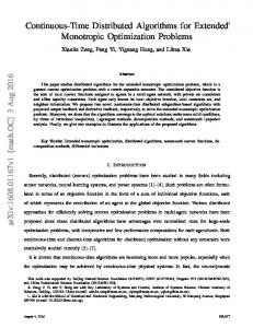
obstacle (no matter how it is modeled) is much simpler than with more complex (but probably more accurate) link models. The locations of the cylispheres used to model a manipulator are determined based on the forward kinematics for that manipulator. The forward kinematics provides transformation matrices from predetermined points on the manipulator to the global coordinate frame. The endpoints for each cylisphere have a fixed offset from one of these predetermined points. Therefore, the endpoints of the cylispheres move as the transformation matrices change due to manipulator motion. A detailed description of transformation matrices and forward kinematics is in [22]. For obstacle avoidance, it is extremely important to always know the minimum distance between a manipulator and all the surrounding obstacles. In their research, Perry and Tesar [21] developed functions for determining minimum distances between a cylisphere and a sphere. Figure 3 shows the picture used to derive the minimum distance between a cylisphere and a sphere. In this figure, Line 1 is a cylisphere with a zero radius, and point P3 is a sphere with a zero radius. The shortest line, Line 2, between Line 1 and point P3 is perpendicular to Line 1. Point P4 is the only point on both lines. The location of point P4 can be found by representing both lines parametrically and then solving for the location of point P4 in terms of the location of the other three points: P1, P2, and P3. Any point on Line 1 can be represented parametrically as:
Figure 3. Derivation of the distance between a cylisphere and sphere
Similarly, any point on Line 2 can be represented parametrically as:
x x3 ( x 4 x3 )t 3 y y ( y y )t (2) 4 3 3 3 z z 3 ( z 4 z 3 )t 3 Since point P4 is located on both Line 1 and Line 2, Equation (2) can be rewritten as:
x x3 ( x1 ( x 2 x1 )t1 x3 )t 3 y y ( y ( y y )t y )t (3) 1 2 1 1 3 3 3 z z 3 ( z1 ( z 2 z1 )t1 z 3 )t 3 Now, since Line 1 is perpendicular to Line 2, it is required that:
( x 2 x1 ) x1 ( x 2 x1 )t1 x3 ( y y ) y ( y y )t y 0 (4) 1 1 2 1 1 3 2 ( z 2 z1 ) z1 ( z 2 z1 )t1 z 3 Solving the above for t1, we obtain:
t1
2
X t Yt Z t
( x 2 x1 ) ( y 2 y1 ) 2 ( z 2 z1 ) 2
(5.1)
Where
X t ( x 2 x1 )( x1 x3 ) Yt ( y 2 y1 )( y1 y 3 ) (5.2)
Y
Z t ( z 2 z1 )( z1 z 3 ) P4(x4,y4,z4) (desired)
P2(x2,y2,z2)
Line 2 (desired)
Line 1
Solving for t1 provides the location of a point P4 on the line running through points P1 and P2, but the desired point P4 is located on the line segment connecting points P1 and P2. Therefore, for a general purpose, another parameter (such as t) must be defined such that:
P3(x3,y3,z3)
0, t1 0 t 1, t1 1 t1 , 0 t1 1
P1(x1,y1,z1) X
Z
x x1 ( x 2 x1 )t1 y y1 ( y 2 y1 )t1 z z1 ( z 2 z1 )t1
(6)
Point P4 can be calculated as:
x 4 x1 ( x 2 x1 )t P4 y 4 y1 ( y 2 y1 )t (7) z 4 z1 ( z 2 z1 )t
(1)
17 Int J Adv Robotic Sy, 2011, Vol. 8, No. 6, Special Issue Robot Manipulators, 14-36
www.intechweb.org
From Equations 6 and 7 we conclude that:
0 t 1
if P4 P1
(8)
if P4 P2
The minimum distance between the cylisphere and the sphere is:
Dm ( x 4 x3 ) 2 ( y 4 y 3 ) 2 ( z 4 z 3 ) 2 (9) For a cylisphere and a sphere that both have a non‐zero radius, the minimum distance is calculated as discussed above, then the radii of both cylisphere and sphere (RL and RO, respectively) are subtracted from the zero‐radius minimum distance to give the true minimum distance, Dmin , as in Equation (10) below, which we will use.
Dmin Dm ( R L R0 ) (10)
3. Formulation of the Path Generation Problem Consider a robot manipulator with M degrees of mobility and N task space coordinates. Assume that a desired Cartesian path, Pdc, is given, the problem is to find the set of joint paths, P, such that the accumulative deviation between the generated Cartesian path, Pgc, and the desired Cartesian path, Pdc, is minimum. In other words, we are interested in the determination of a set of feasible joint angles, which corresponds to a set of desired spatial coordinates of the end‐effector in the task space. In our approach, the desired geometric Cartesian path is uniformly sampled. The number of sampling points (path points or knots) is specified by the programmer and depends on the desired accuracy of the generated path. The accuracy of the generated path increases as the number of path points increases. However, a limiting case for this number is the path update rate; that is, we can increase the number of path points until we reach the limit N K Tt Pur (11) where Nk is the number of knots along the geometric path, Tt is the total traveling time from the starting configuration to the final configuration along the desired path, and Pur is the path update rate of the manipulator. The path update rate is normally within the range 20‐200 Hz for most robotic applications [22]. As an example, the path update rate for the PUMA 560 series robot is about 36 Hz [23]. This means that if the expected traveling time is 3 seconds, the number of knots along the desired path
www.intechweb.org
is 108 points. For a 20 Hz path update rate, the number of points will be 60. Generally, the number of knots along the path should not exceed Nk in Equation (11). It is to be noted that after the sampling process, Pdc and Pgc are matrices of dimension N N K while P is a matrix of M N K dimension. After sampling the
geometric path at the path update rate for best accuracy, the generated values of the joint angles using the continuous genetic algorithm, P, are used by the direct (forward) kinematics model of the robot to obtain the generated Cartesian path given by Pgc FK ( Pθ ), (12)
where Fk represents the robot forward kinematics model. The deviation between the desired Cartesian path, Pdc, and the generated Cartesian path, Pgc, at some general path point, i, is given as
E (i )
N
Pdc (k , i ) Pgc (k , i) .
K 1
(13)
The accumulative deviation between the two paths (desired and generated) depends on whether the initial and final joint angles corresponding to the initial and final configurations of the end‐effector are given in advance using the inverse kinematics model of the manipulator or through another numerical technique (fixed end points), or the case in which the initial and final joint angles are not given (free end points). We are concerned with the latter case in our work since our workspace involves obstacles and so we cannot restrict the initial and final configurations of the end‐effector beforehand. The accumulative deviation between the two paths is, therefore, given by the formula Nk N
Nk
i 1 k 1
i 1
E Pdc (k , i) Pgc (k , i) E (i ) (14) The fitness function developed, a nonnegative measure of the quality of individuals, is defined as
F
1 (15) 1 E P
where P is the penalty function which equals the summation of the penalties of the distance calculation variables and E is the deviation function. In [16], F was a function of E alone since the environment did not involve any obstacles. However, we now introduce P so that the fitness of the solution depends on both its closeness to the desired path as well as the distance from the obstacles. The procedure for calculating the penalty function, P, is given in the following steps:
Za’er S. Abo-Hammour, Othman MK. Alsmadi, Sofian I. Bataineh, Muhannad A. Al-Omari and Nafee’ Affach: Continuous Genetic Algorithms for Collision-Free Cartesian Path Planning of Robot Manipulators
18
For each path point across the generated path using CGA, find the position of each joint in the Cartesian space using the forward kinematics model of the given manipulator. Calculate the minimum distance, D min , between all the links (assuming L links) and all the obstacles (assuming O obstacle) surrounding the robot as given in Equation (10). This will include L×O calculations of Dmin . From the calculated values of D min at all path points, the following values are computed: D min All , the least value of Dmin encountered throughout the path. This is the minimum value of all L×O×Nk calculations. Find the number of collisions, N col , along the path (i.e. when Dmin 0 ). If the value of D min All is found to be greater than or
equal to a predefined threshold safe guard distance, , then the robotic arm is clear from the obstacles and the penalty function, P, is set to zero. If, however, D min All is less than , then, P is calculated
as the weighted sum of functions that depends on N col ,
D min All according to the following equation :
P Pmin w D min PD min w NC PNC
where
PD min
(16)
D min All (17)
PNC
N col Nk
(18)
Equation 16 shown above is used to discriminate between candidate solutions that have the minimum distance ( D min All ) less than . To handle this situation, two scenarios might be used. The first one sets P to a certain constant value of penalty for all solutions suffering from such condition. However, this scenario equates all solutions with D min All . For example, two candidate solutions might have the same value of D min All . However, the first one has N col =1, while the second solution has N col = 10. Obviously, the first solution is better than the second one. According to the discussed scenario, both of them will be given the same P value which is unfair. In order to eliminate this problem, we introduced Equation (16), second scenario, to deal with the solutions in the gray scale rather than the black and white levels only. In our case, it is assumed that 19 Int J Adv Robotic Sy, 2011, Vol. 8, No. 6, Special Issue Robot Manipulators, 14-36
Pmin wD min w NC 1
(19)
Hence, we have set w D min 0.3 , w NC 0.5 , and
Pmin 0.2 . This means that the penalty is more sensitive to the number of collisions (with Dmin 0 ) than the case with Dmin 0 . In addition to that, if we have D min All , then the minimum penalty value is 0.2 to differentiate between this case and the case with D min All where p = 0. It is to be noted that P in Equation (16) has a range of values [0.2,1]. The minimum value of P, which is 0.2, appears in the case where no collisions are encountered and D min All . On the other hand, the maximum value of P, which is 1, appears in the case where the number of collisions across the generated path is equal to N k . Concerning the value of , it can be assumed any small positive number according to the userʹs specification. It might depend on the flexibility of the manipulator links and the vibrations encountered during the execution of the motion. In our case, we have set it to a value of 10 mm. 4. Continuous Genetic Algorithms (CGAs)
Genetic Algorithms (GAs) were developed by John Holland [16] and are based on principles inspired from the genetic and evolution mechanisms observed in natural systems. Their basic principle is the maintenance of a population of solutions to the problem that evolves towards the global optimum. They are based on the triangle of genetic reproduction, evaluation and selection [24]. Genetic reproduction is performed by means of two basic genetic operators: crossover and mutation. Evaluation is performed by means of the fitness function that depends on the specific optimization problem. Selection is the mechanism that chooses parent individuals with probability proportional to their relative fitness for the mating process. Genetic algorithms can be distinguished from calculus‐ based and enumerative methods for optimization by the following characteristics [2]: I. GAs search for optimal solutions using a population of individuals; this very important characteristic gives GAs much of their search power and also points to their parallel nature. II. GAs use only objective function information. Much of the interest in genetic algorithms is due to the fact that they belong to the class of efficient, domain‐independent search strategies that are usually superior in performance to traditional methods without the need to incorporate highly domain‐specific knowledge.
www.intechweb.org
www.intechweb.org
1)
Initialization: Randomly generating an initial population comprising Np smooth individuals. Two smooth functions are proposed for initializing the population: the modified Gaussian function and the tangent hyperbolic function [16]. The modified Gaussian function is given as follows:
θ final (h) θ initial (h) PJ (h, i ) θ initial (h) N 1 K (i μ) 2 (i 1) A exp 2σ 2
(20)
while the tangent hyperbolic function is governed by the equation:
P j (h, i ) θ initial (h) (θ final (h) θ initial (h)) (21)
i μ 0.51 tanh σ
for all 1 h M and 1 i N k , where Pj��,i� is the ith
path point angle of the hth joint for the jth parent,
θinitial��� is the initial angle of the hth joint at the initial
configuration of the end‐effector, θfinal(h) is the final angle of the hth joint at the final configuration of the end‐ effector, Nk is the total number of knots (sampling points) across the Cartesian path, A represents a random number where within the range [������, �����],
R(h) θ final (h) θ initial (h) , is a random number
within the range [1, Nk], and is a random number within the range [1, Nk /6]. The difference between these two functions lies in the fact that the modified Gaussian function results in an overshoot or an under shoot, while the tangent hyperbolic function does not result in either. For both functions, specifies the center of the function, while specifies its degree of dispersion. The two initialization functions are shown in Figure 4.
140
Tangent Hyperbolic Function Modified Gaussian Function
120
Joint Angle (Degree)
III. GAs use probabilistic transition rules, not deterministic rules in contrast with the calculus‐ based and enumerative methods. The population‐based nature of GAs gives them two major advantages over other optimization techniques. First, it identifies the parallel behavior of GAs that is realized by a population of simultaneously moving search candidate solutions [17]. This advantage significantly reduces the CPU operation time. Second, information concerning different regions of solution space is passed actively between the individuals by the crossover procedure. This advantage makes GAs an efficient and robust method for optimization, particularly for the optimization of nonlinear functions. On the other hand, the population‐based nature of GAs also results in two main drawbacks. First, more memory space is occupied, and second, GAs normally suffer from computational burden when applied on sequential machines. This means that the time required for solving certain problem using GAs will be relatively large. However, the solution time is a major point when we are interested in real time applications. But if off‐line solutions are required for any real‐life problem, then our major concern will be the accuracy of the solution rather than the time required for the solution. For real‐life problems, the computational time might be reduced to achieve real‐time processes utilizing its parallel nature which can be applied on parallel computers or FPGAs [25]. The fact that GAs use only objective function information without the need to incorporate highly domain‐specific knowledge, points to both the simplicity of the approach from one side and its versatility from the other side. This means that once a GA is developed to handle a certain problem, it can easily be modified to handle other types of problems by changing the objective function in the existing algorithm. This is why GAs are classified as general‐purpose search strategies. The stochastic behavior of GAs cannot be ignored as a main part that gives them much of their search efficiency. GAs employ random processes to explore a response surface for a specific optimization problem. The advantage of this behavior is the ability to escape local minima without supervision [25]. The CGA is that algorithm which depends on the evolution of curves in one‐dimensional space. In general, CGAs use smooth operators and avoid sharp jumps in the parameter value. For a discussion on the justification for using CGAs to produce smooth, accurate paths for robotic manipulators, the reader is referred to [16]. The CGAs have the same steps as in a typical genetic algorithm; the steps of the continuous genetic algorithm used in this paper are as follows:
100 80 60 40 20 0
10
20
30
40
50
60
70
80
90
100
Path Point (i)
Figure 4. Initialization Functions Used in the Continuous Genetic Algorithm.
Za’er S. Abo-Hammour, Othman MK. Alsmadi, Sofian I. Bataineh, Muhannad A. Al-Omari and Nafee’ Affach: Continuous Genetic Algorithms for Collision-Free Cartesian Path Planning of Robot Manipulators
20
4)
C L W (h, i ) P (h, i ) (1 W (h, i )) Pk (h, i ) (22) C L 1 1 W (h, i ) P (h, i ) W (h, i ) Pk (h, i ) (23)
0 -20
Joint Angle (Degree)
3)
Evaluation: The fitness, which reflects the degree of goodness of the individual, is calculated for each individual in the population as given in Equation (15). Selection: In the selection process, the best individuals receive more copies in subsequent generations so that their desirable traits may be passed onto their offspring. Due to the probabilistic nature of selection, individuals can merely be expected, but not guaranteed, to reproduce in proportion to their fitness. Crossover: Crossover provides the means by which valuable information is shared among the population. It combines the features of two parent individuals, say j and k, to form two children individuals, say L and L+1, that may have new patterns compared to those of their parents, and plays a central role in GAs. The crossover process in our algorithm is expressed as
-40 -60 -80 -100 -120 20
40
60
80
100
Path Point (i)
(b)
1.0
0.8
Function Value
2)
0.6
0.4
0.2
0.0
i μ W (h, i ) 0.51 tanh (24) σ
20
40
60
80
100
Path Point (i)
(c)
for all 1 h M and 1 i N k , where Pj and Pk
represent the two parents chosen from the mating pool,
0
-20
Joint Angle (Degree)
CL and CL�1 are the two children obtained through the crossover process, W represents the crossover weighting function within the range [0, 1], is a random number within the range [1, Nk], and σ is a random number within the range [1, Nv /6].
-40
-60
-80
-100
0
20
Joint Angle (Degree)
40
60
80
100
Path Point (i)
-20
(d)
-40
-60 0
-80
20
40
60
Path Point (i)
(a)
80
100
Joint Angle (Degree)
-20
-100
-40
-60
-80
-100
-120
20
40
60
Path Point (i)
(e)
80
100
Figure 5. Crossover Process, a) 1st Parent, b) 2nd Parent, c) Weighting Function, d) 1st Child, e) 2nd Child.
21 Int J Adv Robotic Sy, 2011, Vol. 8, No. 6, Special Issue Robot Manipulators, 14-36
www.intechweb.org
For the crossover operator, in our method, pairs of individuals are crossed with probability Pci. Within the pair of parents, individual curves are crossed with probability Pcj; that is, the smooth curve of the hth joint in the first parent is crossed with that of the hth joint in the second parent with Pcj probability. If we set Pci value to 0.5 and Pcj to 0.5, then in probability one pair of parents between two pairs is to be crossed, and within that pair, M/2 of the joints will be crossed. If we set Pcj value to unity, then each joint in the first parent is crossed with the similar joint (1st with 1st, 2nd with 2nd, and so on) in the second parent. Figure 5 shows the crossover process between two random joints’ paths corresponding to the hth joint in the first parent and the hth joint in the second parent. It is clear that new information is incorporated in the children while maintaining the smoothness of the resulting paths. 5) Mutation: The purpose of mutation is to introduce occasional perturbations to the parameters to maintain genetic diversity within the population. The mutation process in our algorithm is governed by the following formulas:
0
Joint Angle (Degree)
-20
-40
-60
-80
-100 20
Function Value
40
30
20
10
0 20
40
60
80
100
Path Point (i)
(b)
where Cj represents the jth child produced through the crossover process, Cjm is the mutated jth child, M is the Gaussian mutation function, d represents a random number within the range [‐range(h), range(h)], with range(h) representing the difference between the minimum and maximum values of the child Cj, and and are as given in the crossover process.
0
Joint Angle (Degree)
-20
-40
-60
-80
-100 20
www.intechweb.org
100
50
(26)
In the mutation process, each individual child undergoes mutation with probability Pmi. However, for each child that should undergo a mutation process, individual joints are mutated with probability Pmj. If the Pmi value is set to 0.5 and the Pmj value is set to 0.5, then one child out of two children is likely to be mutated, and within that child, M/2 of the joints’ paths are likely to be mutated. Figure 6 shows the mutation process in a solution curve of a certain child. As in the crossover process, some new information is incorporated in the children while maintaining the smoothness of the resulting solution curves.
80
(a)
(i μ) M (h, i ) exp 2σ 2
60
Path Point (i)
C mj (h, i ) C j (h, i ) dM (h, i ) (25) 2
40
40
60
Path Point (i)
(c)
80
100
Figure 6. Mutation Process, a) First Child, b) Mutation Function, c) Mutated Child.
6)
7)
Replacement: After generating the offspringʹs population through the application of the genetic operators to the parents` population, the parents` population is totally or partially replaced by the offspringʹs population. This completes the “life cycle” of the population. Termination: The GA is terminated when some convergence criterion is met. Possible convergence criteria are: the fitness of the best individual so far found exceeds a threshold value, the maximum number of generations is reached, or the progress limit (the improvement in the fitness value of the best
Za’er S. Abo-Hammour, Othman MK. Alsmadi, Sofian I. Bataineh, Muhannad A. Al-Omari and Nafee’ Affach: Continuous Genetic Algorithms for Collision-Free Cartesian Path Planning of Robot Manipulators
22
member of the population over a specified number of generations being less than some predefined threshold) is reached. After terminating the algorithm, the optimal solution of the problem is the best individual so far found. To summarize the evolution process, an individual is a candidate solution of the joints’ angles; i.e. each individual consists of M joints’ paths, each consisting of Nk variables. This results in a two‐dimensional array of size M Nk. The population undergoes the selection process, which results in a mating pool within which pairs of individuals are crossed with probability Pci. Within that pair of parents, individual solution curves are crossed over with probability Pcj. This process results in an offspring generation where every individual child undergoes mutation with probability Pmi. Within that child, individual joints are mutated with probability Pmj. After that, the next generation is produced according to the replacement strategy applied. This process is repeated till the convergence criterion is met where the M Nk parameters of the best individual are the required joints’ angles. The final goal of discovering the required joints’ paths is translated into finding the fittest individual in genetic terms. The block diagram of the CGA is given in Figure 7. Parameterization
Initial population Replace parent population by offspring population
Parent population
Fitness evaluation
No Offspring population
Genetic operations Selection Crossover Mutation
GA termination
Yes Stop iteration
Figure 7. Block diagram of the typical genetic algorithm.
In addition to the previous operators, the new algorithm includes methods for ensuring that the jointsʹ angles remain within the allowed range while maintaining smoothness. Moreover, we introduce the elitism and the ʺextinction and immigrationʺ operators; the elitism operator ensures that the fitness of the best candidate solution in the current population must be larger than or equal to that of the previous population, while the 23 Int J Adv Robotic Sy, 2011, Vol. 8, No. 6, Special Issue Robot Manipulators, 14-36
ʺextinction and immigrationʺ operator is used in some cases to avoid stagnation in the GA (when all individuals in the population are identical or when the improvement in the fitness value of the best individual over a certain number of generations is less than some threshold value) by first removing all of the individuals in the current generation except for the best‐of‐generation individual, and then filling out the extinct population by means of both generation (as in the initialization phase) and continuous mutations to the best‐of‐generation individual. Please refer to [16] for further details. 5. Simulation Results The proposed technique is used to solve the Cartesian path generation problem with obstacle avoidance for robot manipulators. The input data to the algorithm is divided into two parts: the genetic‐algorithm‐related parameters and the problem‐related parameters. The genetic‐algorithm‐related parameters include the population size, Np, the initialization function, the individual crossover probability, Pci, the joint crossover probability, Pcj, the individual mutation probability, Pmi, the joint mutation probability, Pmj, the method used when the joints’ angles exceed the joint limit, the immigration threshold value, the corresponding number of generations, and finally the termination criterion. The problem‐related parameters include the link parameters, the number of joints in the manipulator, M, the robot’s degrees of freedom, N (compare to beginning of 3.0, task space coordinates), the number of path points, Nk, the joints’ limits �lower��� and upper��� for ������ M�, and the desired Cartesian path �Pdc�k�i� for k����� N and i����� Nk�. Regarding the initial and final joints’ angles (initial��� and final��� for ������ M), and in the free end points case, the end points are not considered as input parameters to the algorithm since they are not given. We also need to specify the position of the obstacles relative to the manipulator base. The initial settings of the CGA parameters are as follows: the population size is set to 500 individuals. The tangent hyperbolic function given in Equation (21) is used in the initialization phase. The individual crossover probability is kept at 0.9; the joint crossover probability is also set to 0.9. The individual mutation probability and the joint mutation probability are kept at 0.9. We use the rank‐ based selection scheme, which chooses a prescribed number of parent individuals with the highest fitness according to the rank‐based ratio, Rrb, and performs the mating process by choosing parents at random from this subpopulation of the size RrbNp. The rank‐based ratio is set to 0.5. The generational replacement scheme is used, where the parent population is totally replaced by the offspring population except for the parents’ elite individuals, where the number of elite parents to be
www.intechweb.org
passed on to the next generation is one‐tenth of the population (0.1Np). The extinction and immigration operator is applied when the improvement in the fitness value of the best individual over 400 generations is less than 0.01. The genetic algorithm is stopped when one of the following conditions is met. First, the fitness of the best individual of the population reaches a value of 0.99. Second, the maximum deviation at any path point of the best individual is less than or equal to 0.001m. Third, a maximum number of 10000 generations is reached. Fourth, the improvement in the fitness value of the best individual in the population over 1000 generations is less than 0.01. It is to be noted that the first two conditions indicate a successful termination process (optimal solution is found), while the last two conditions point to a partially‐successful end depending on the fitness of the best individual in the population (near‐optimal solution is reached). Throughout this paper, the convergence speed of the algorithm, whenever used, means the average number of generations required for convergence. The CGA is written in Visual Basic environment. Due to the stochastic nature of GAs, twelve different runs were made for every result obtained in this work using a different random number generator seed; results are the average values whenever possible. The path generation problem considered in this work may be divided into two main categories depending on the number of solutions obtained: Multiple solutions: This is the case of non‐redundant manipulators where the initial and final joints’ angles corresponding to the initial and final configurations of the end‐effector are not given. The algorithm automatically finds one smooth solution out of the existing solutions every time it is executed. The number of multiple solutions depends on the number of joints in the manipulator, the link parameters, the allowable range of motion of the joints, and the location of obstacles. For example, the 2R planar manipulator has two solutions while the PUMA 560 has four different solutions [1]. The different solutions are due to differences in the arm and elbow configurations [1,16] Unique solution category: It is in which the initial and final joints’ angles corresponding to the initial and final configurations of the end‐effector of non‐redundant manipulators are specified, is not considered in our work. This is because if the unique path solution involves collisions with obstacles, then no valid solution to our problem of path planning with obstacle avoidance exists. For the multiple solutions category, the 2R planar and PUMA manipulators were chosen. In what follows, we describe in detail the results obtained for the path generation problems involving those
www.intechweb.org
manipulators. For both categories, the algorithm will be implemented for two different sets of desired paths:
Path (1):
1 x final 0.1 π 8 x final x initial (i 1) Pdc (1, i ) X dc (i ) x initial N k 1 x initial 0.1,
(27)
Pdc (2, i ) Ydc (i ) 0.25 0.25 sin8(1, i ) x initial ) Pdc (3, i ) Z dc (i) 0,
1 i Nk
In addition, there are two obstacles in space ��, �, �� at the following locations: Obstacle–1 = (‐0.2, 0.46, 0)cm; Obstacle–2 = (0.1, ‐0.57, 0)cm. The radii of the obstacles are 5 cm for Obstacle–1 and 7 cm for Obstacle–2.
Path (2):
x initial 0.2,
x final 0.4,
Pdc (1, i ) X dc (i ) x initial
z 0, for the 2 - R manipulator
x final x initial N k 1
(i 1)
(28)
Pdc ( 2, i ) Ydc (i ) X dc (i) Pdc (3, i ) Z dc (i) 0.25,
1 i Nk
In addition, there are two obstacles in space ��, �, �� at the following locations: Obstacle–1 = (0.5,0.5,0)m ; Obstacle–2 = (0.5,0.8,0)m . The radii of the obstacles are 5 cm for Obstacle–1 and 7 cm for Obstacle–2. 5.1. Multiple solutions for the 2R manipulator The algorithm is used to solve the path generation problem of 2R planar and PUMA manipulators. For the 2R manipulator, the link parameters are L1 � L2 � L � 0�� m and the link radius is assumed to be zero. For this case, � � 2, � � 2, lower��� � –180˚ and upper��� � 180˚ for ��1, 2. The forward kinematics model is given by [1]:
Pgc (1,i ) X gc (i )
L1 cos(θ1 ) L2 cos(θ1 θ 2 ) L1 cos( Pθ (1, i ))
(29,1)
L2 cos( Pθ (1, i ) Pθ (2, i ))
Pgc (2, i ) Ygc (i ) L1 sin(θ1 ) L2 sin(θ1 θ 2 ) L1 sin( Pθ (1, i ))
(29,2)
L2 sin( Pθ (1, i ) Pθ (2, i ))
where 1 i N k .
Za’er S. Abo-Hammour, Othman MK. Alsmadi, Sofian I. Bataineh, Muhannad A. Al-Omari and Nafee’ Affach: Continuous Genetic Algorithms for Collision-Free Cartesian Path Planning of Robot Manipulators
24
A solution of Path 1 above includes a collision whereas solutions of Path 2 do not. However, as seen in Equation (16), the choice of a solution does not depend only on being collision‐free, but also on minimizing the distance from the obstacles throughout the path and incorporating the penalty value, which depends on the distances, in the fitness function expressed in Equation (15). Therefore, the best solution will be the safest solution is the one ensuring maximum clearance from the obstacles as well as the one that exhibits maximum fitness. The deviation between the desired path and the generated path at some general path point, i, is given in Equations (13), while the accumulative deviation between the desired and generated paths is given in Eq. (14). 5.1.1. Path 1 for the 2R manipulator To analyze the results for the two paths given in Equations (27) and (28), we start with Path 1. Solving for the 2R manipulator, two solutions are obtained by the closed loop form kinematics model of the manipulator. The two solutions are seen in Figures 8 and 9, with details seen in Table 1, where one is feasible and obstacle free and the other is not. The proposed GA was executed for this path and, as expected, the first solution (feasible) was selected, while the second solution was never selected. Please note that the infeasible solution is presented to only see that there would be some infeasible solutions; however, they would not be selected by our approach. The GA would in fact always select the feasible solution only. In Table 1, the maximum fitness value obtained for the first solution using the GA is 0.9578474. It is also seen that minimum distance between all links and all obstacles across the generated paths is 0.3624 m which takes a place at point 7.
the 2R manipulator to reach the optimal solution from the near‐optimal one. This shows that most of the computational burden of the algorithm is spent in the fine‐tuning stage whereas the near‐optimal solutions are found very early in the course of the CGA.
Figure 9. Second solution for the 2R Planar Manipulator (PATH 1).
Criteria
Path 1 First solution Selected by CGA Selected F max 0.9578474 Collision Free Yes Joint limit feasibility Feasible D_min_all 0.3624 D_min_all sample 7 point
Second solution Not selected ‐ No ‐ ‐ ‐
Table 1. Results for the 2R manipulator for Path 1.
Figure 10. Evolutionary Progress for the Best‐of‐Generation Individual Regarding the 2R Planar Manipulator for the first solution (PATH 1).
Figure 10 shows the evolutionary progress plots of the best‐fitness individual for the 2R manipulators. It is noted that the algorithm takes about 35 generations for the 2R manipulator to reach a near‐ optimal solution with a fitness value of 0.8, while it takes about 70 generations for
The 2R manipulator has two possible solutions for path 1. In our case, one feasible solution is obtained for the 2R manipulator in path 1 because the other solution is not collision free. Figures 11 and 12 show the generated path obtained using the CGA and its deviation from the desired one. It is clear that the deviation does not exceed
Figure 8. First solution for the 2R Planar Manipulator (PATH 1).
25 Int J Adv Robotic Sy, 2011, Vol. 8, No. 6, Special Issue Robot Manipulators, 14-36
www.intechweb.org
0.001 m for the 2R configuration, which proves the effectiveness of the CGA in generating paths with minimum deviation from desired ones. In addition, the generated path, for the 2R case, does not pass through obstacle positions and is thus collision‐free.
(a)
Figure 11. Path Point deviations for the 2R Planar Manipulator for the first solution.
(b)
Figure 13. Joints Paths of 2R planar manipulator for the first solution, a) First Joint, b) Second Joint
(a)
(b)
Figure 12. Desired and generated Cartesian path for the 2R manipulator for the first solution in a) x‐axis, b) y‐axis
Figure 14 below shows the evolution of three different path points (1, 50, and 100) for the two joints of the 2R manipulator. It is observed that the near‐optimal solution is reached within around 30 generations while the remaining number of generations is spent in the fine tuning stage. The results shown in Figures 10 through 14 relate to Path 1 as given in Equation (27), which has one collision‐free solution for the 2R manipulator. For the 2R manipulator, as shown in Figure 13, the ranges of the joints’ angles in the solution found are [‐30, ‐6] for the first joint and [108, 148] for the second joint. The joints’ limits are [‐180, 180] for both joints. This goes in agreement with the previous conclusion that the algorithm finds solutions within the allowed range of joint angles.
www.intechweb.org
Za’er S. Abo-Hammour, Othman MK. Alsmadi, Sofian I. Bataineh, Muhannad A. Al-Omari and Nafee’ Affach: Continuous Genetic Algorithms for Collision-Free Cartesian Path Planning of Robot Manipulators
26
(a)
Figure 15. First solution for the 2R Planar Manipulator (PATH 2).
Figure 16. Second solution for the 2R Planar Manipulator (PATH 2).
(b)
Figure 14. Evolution of different indicated path points of 2R planar manipulator for the first solution for a) First Joint, b) Second Joint
5.1.2 Path 2 for the 2R manipulator As given in Equation (28), Path 2 will now be shown to have more than one collision‐free solution. As illustrated in the previous subsection, the chosen solution will be determined using the proposed GA approach based on the maximum fitness as well as the minimum distance as expressed in Equations (16) and (17). Performing the GA simulation provided the results shown in Figures 15 and 16 and Table 2. As seen in Table 2, there are two feasible solutions. However, the solution with the maximum distance between the obstacles and the links across the generated path is the one that is selected by the GA approach. That is, the algorithm ignores the second feasible solution with D min All 0.2679m and selects the
Criteria
Path 2 First solution Selected by CGA Selected F max 0.9579605 Collision Free Yes Joint limit feasibility Feasible D_min_all 0.4123 D_min_all sample 100 point
Second solution Not selected ‐ Yes Feasible 0.2679 1
Table 2. Results for the 2R manipulator for Path 2.
first solution with D min All 0.4123m since the first solution is safer than the second solution being farther of hitting the obstacle.
Figure 17. Evolutionary progress plot for the Best‐of‐Generation individual regarding the multiple solutions category for the 2R Planar Manipulator for the first solution.
27 Int J Adv Robotic Sy, 2011, Vol. 8, No. 6, Special Issue Robot Manipulators, 14-36
www.intechweb.org
Figure 17 shows that the solution for Path 2 shows an evolutionary progress similar to that of Path 1 (mention no. of generations, etc..). We can conclude again that most of the computational burden of the algorithm is spent in the fine‐tuning stage, whereas the near optimal solutions are found very early. As also observed, Figure 18 and Figure 19 show the generated path obtained using the CGA and its deviation from the desired one.
Regarding joint limits, Figure 20 shows that, once again, the solutions are within the allowed range. The ranges of the joints’ angles for the 2R manipulator are [‐29, ‐11] for the first joint and [112, 148] for the second joint, which are within the [‐180, 180] range allowed for both joints.
(a)
Figure 18. Path Point deviation for the 2R Planar Manipulator for the first solution.
(b) (a)
Figure 20. Joints Paths of the 2R planar manipulator for the first solution, a) First Joint, b) Second Joint
Finally, Figure 21 shows the evolution of the path points for the two joints of the 2R manipulator. In both cases, around 30 generations were needed to reach a near‐ optimal solution whereas the larger part of the algorithm was needed to fine‐tune the solutions. Figure 22 below also show the evolutionary progress of the minimum distances for the 2R manipulator.
(b)
Figure 19. Desired and generated Cartesian path for 2R manipulator for the first solution in a) x‐axis, b) y‐axis www.intechweb.org
Za’er S. Abo-Hammour, Othman MK. Alsmadi, Sofian I. Bataineh, Muhannad A. Al-Omari and Nafee’ Affach: Continuous Genetic Algorithms for Collision-Free Cartesian Path Planning of Robot Manipulators
28
5.2. Multiple Solutions for the PUMA manipulator Here, the link radius is assumed to be zero with the link parameters and the joints’ limits given in Table 3. For this case, N��, ���, the forward kinematics model is given in [23]. For the PUMA manipulator, the z‐coordinates are kept at zero in the first path but have a value in the second. This degree of freedom is not taken into consideration for the planar case. The Nk, is 100 points.
(a)
Joint Number αh‐1 (h) 1 0° 2 ‐90° 3 0° 4 ‐90° 5 90° 6 ‐90°
ah‐1
dh
θh θlower(h) θupper(h)
0 0 0.4318 0.02032 0 0
0 0 0.14909 0.43307 0 0
Θ1 Θ2 Θ3 Θ4 Θ5 Θ6
‐160° ‐225° ‐45° ‐110° ‐100° ‐266°
160° 45° 225° 170° 100° ‐266°
Table 3. Link Parameters and Jointsʹ Limits of the PUMA 560 Manipulator.
(b)
Figure 21. Evolution of different indicated path points of the 2R planar manipulator for the first solution for a) First Joint, b) Second Joint
Figure 22. Minimum distance for the 2R planar manipulator for
the first solution.
As seen in Equation (16), the choice of a solution does not depend on only being collision‐free, but also on maximizing the distance from the obstacles throughout the path and incorporating the penalty value, which depends on the distances, in the fitness function expressed in Equation (15). Therefore, the best solution will be the safest solution (the one ensuring maximum clearance from the obstacles as well as the one that exhibits maximum fitness). The deviation between the desired path and the generated path at some general path point, i, is given in Equations (13), while the accumulative deviation between the desired and generated paths is given in Equation (14). 5.2.1 Path 1 for the PUMA manipulator Figure 23 and Figure 24 show the feasible solutions while Figure 25 and Figure 26 show the unfeasible solutions for the PUMA manipulator in path 1 as obtained from the closed form solution of the inverse kinematics model. Table 4 shows the detailed information about the solutions for Path 1. As seen in Table 4, there are four solutions where the selected feasible one is Solution 3. This solution is selected by the GA approach since it has a distance of 0.3066m (between the links and the obstacles) while the other feasible solution (solution 1) has a distance of 0.2991m, which makes it not as safe as Solution 3.
29 Int J Adv Robotic Sy, 2011, Vol. 8, No. 6, Special Issue Robot Manipulators, 14-36
www.intechweb.org
Figure 23. First feasible solution for the PUMA Manipulator PATH 1 (Solution (1)).
Figure 26. Second unfeasible solution for the PUMA Manipulator PATH 1 (Solution (4)).
Criteria
Solution 1 Selected by Not CGA selected F max ‐ Collision Yes Free Joint limit Feasible feasibility D_min_all 0.2991 D_min_all 3 sample point
Solution 2 Not selected ‐ Yes
Solution Solution 3 4 Selected Not selected 0.947 ‐ Yes Yes
Not feasible ‐ ‐
Feasible 0.3066 8
Not feasible ‐ ‐
Table 4. Results for the PUMA manipulator, Path 1.
Figure 24. Second feasible solution for the PUMA Manipulator PATH 1 (Solution (3)).
Figure 27 shows the evolutionary progress plots of the best‐fitness individual for the PUMA manipulator. It is noted that the algorithm takes about 80 generations for the PUMA manipulator to reach a near‐optimal solution with a fitness value of 0.8, while it takes about 170 generations for the PUMA manipulator and about 70 generations to reach the optimal solution from the near‐ optimal one. It is also clear that the PUMA manipulator takes about 2.4 the number of generations of the 2R manipulator to reach the optimal solution.
Figure 25. First unfeasible solution for the PUMA Manipulator PATH 1 (Solution (2)).
www.intechweb.org
Za’er S. Abo-Hammour, Othman MK. Alsmadi, Sofian I. Bataineh, Muhannad A. Al-Omari and Nafee’ Affach: Continuous Genetic Algorithms for Collision-Free Cartesian Path Planning of Robot Manipulators
30
Figure 27. The Best‐of‐Generation Individual for the Multiple PUMA solutions Category for Solution 3.
(a)
For the PUMA 560 manipulator, it is known that it can reach certain goals with four different solutions when only the position is taken into account. But due to obstacle avoidance restrictions, some of these four solutions will be eliminated. The 2R manipulator, on the other hand, has two possible solutions. In our case, two feasible solutions are obtained for the PUMA manipulator considering the other two solutions resulted are not feasible by the joint angels. Figures 28 and 29 show the generated path obtained using the CGA and their deviations from the desired ones. It is clear that the deviation does not exceed 0.0007m for the PUMA configuration, which proves the effectiveness of the CGA in generating paths with minimum deviation from desired ones. In addition, the generated path, for the PUMA 560 case does not pass through obstacle positions and is thus collision‐free.
(b)
(c)
Figure 29. Desired and generated Cartesian path for the PUMA manipulator for Solution 3 in a) x‐axis, b) y‐axis, c) z‐axis.
Figure 28. Path Point deviations for the PUMA Manipulator for Solution 3.
31 Int J Adv Robotic Sy, 2011, Vol. 8, No. 6, Special Issue Robot Manipulators, 14-36
Figure 30 shows that the ranges of the joints’ angles for the PUMA 560 solution are given as follows: [12, 47] for the first joint, [‐75, ‐48] for the second joint, and [10, 63] for the third joint. In fact, the joints’ limits, given in Table 3, are [‐160, 160] for the first joint, [‐225, 45] for the second joint and [‐45, 225] for the third joint. It is clear that this solution is acceptable. This means that the algorithm tries to find safe solutions (away from joints’ limits) more frequently than other solutions. www.intechweb.org
(a)
(b)
(c)
(c)
Figure 31 shows the evolution of three different path points (1, 50, and 100) for the three joints of the PUMA 560. It is observed that the near‐optimal solution is reached within around 30 generations. The results shown in Figures 27 through 31 relate to Path 1 as given in Equation (27), which has no collisions for all the solutions of the PUMA manipulator.
www.intechweb.org
(b)
Figure 30. Joints Paths of the PUMA manipulator for Solution 3 for a) First Joint, b) Second Joint, c) Third Joint.
(a)
Figure 31. Different indicated path points of the PUMA manipulator for Solution 3 for a) 1st Joint, b) 2nd Joint, c) 3rd Joint.
5.2.2 Path 2 for the PUMA manipulator Figure 32 and Figure 33 show the feasible solutions while Figures 34 and 35 show the unfeasible solutions for the PUMA manipulator in path 2 as obtained from the closed form solution of the inverse kinematics model. This is also detailed in Table 5. As stated earlier, the PUMA 560
Za’er S. Abo-Hammour, Othman MK. Alsmadi, Sofian I. Bataineh, Muhannad A. Al-Omari and Nafee’ Affach: Continuous Genetic Algorithms for Collision-Free Cartesian Path Planning of Robot Manipulators
32
manipulator has four different solutions when only the position is taken into consideration. Our solution, however, is based on maximum clearance from the obstacles as well as maximum fitness even when there are several possible collision‐free solutions and the best one is chosen based on the same criteria. The results obtained using the GA approach are shown in Figures 36 through 39. As seen in Table 5 and as stated previously, the proposed GA approach selects the path with D min All 0.4229m, which is Solution 3, where on the other hand, rejects all other feasible and infeasible solutions since this path is the safest.
Figure 35. Second unfeasible solution for the PUMA Manipulator PATH 2 (Solution (4)).
Criteria
Figure 32. First feasible solution for the PUMA Manipulator PATH 2 (Solution (1)).
Solution 1 Selected by Not CGA selected F max ‐ Collision Yes Free Joint limit Feasible feasibility D_min_all 0.4134 D_min_all 100 sample point
Solution 2 Not selected ‐ Yes
Solution Solution 3 4 Selected Not selected 0.948 ‐ Yes Yes
Not feasible ‐ ‐
Feasible 0.4229 100
Not feasible ‐ ‐
Table 5. Results for PUMA, Path 2.
Figure 33. Second feasible solution for the PUMA Manipulator PATH 2 (Solution (3)).
Figure 36. The Best‐of‐Generation Individual Regarding the Multiple Solutions Category for the PUMA Manipulator for Solution 3.
Figure 34. First unfeasible solution for the PUMA Manipulator PATH 2 (Solution (2)). 33 Int J Adv Robotic Sy, 2011, Vol. 8, No. 6, Special Issue Robot Manipulators, 14-36
www.intechweb.org
(a)
Figure 37. Path Point deviation for the PUMA Manipulator for Solution 3.
(b) (a)
(b)
(c)
Figure 38. Desired and generated Cartesian path for PUMA
manipulator for Solution 3 in a)x‐axis, b) y‐axis, c)z‐axis
34 Int J Adv Robotic Sy, 2011, Vol. 8, No. 6, Special Issue Robot Manipulators, 14-36
(c)
Figure 39. Joints Paths of PUMA manipulator for Solution 3, a) First Joint, b) Second Joint, c) Third Joint
Regarding joint limits, Figure 39 show that, once again, the solutions are within the allowed range. The ranges of the joints’ angles for the PUMA 560 solution are [13, 28] for the first joint, [‐112, ‐72] for the second joint and [5, 45] for the third joint. Finally, Figure 40 shows the evolution of three different path points (1, 50, and 100) for the three joints of the PUMA 560. In this case, around 30 generations were needed to reach a near‐optimal solution whereas the larger part of the algorithm was needed to fine‐tune the solutions. Figure 41 also shows the evolutionary progress of the minimum distances for both manipulators.
www.intechweb.org
6. Conclusion
(a)
(b)
The CGAs along with the geometry approach have been applied as a path planner for avoiding stationary obstacles in the manipulator’s workspace, known as collision‐free Cartesian path planning of robot manipulators. For avoiding obstacles using the geometry approach, it is important to always know the minimum distance between the manipulator links and all the surrounding obstacles. This will include modeling of obstacles and manipulator’s links in the workspace where obstacles are modeled as spheres, while links are modeled as cylisphere. The locations of the cylispheres, used to model a manipulator’s links, are determined based on the forward kinematics for that manipulator. Then, by using the distance functions to calculate the distance between each link and obstacle, the Cartesian paths that are free of collisions are obtained. The proposed CGA will always select the feasible and safest path that avoids the obstacles within the manipulator joint limits. This safest path is select as the best of all feasible solutions. As a result, it was observed that genetic algorithms can be used as an efficient tool in robotics application, which in our case has two aims; first, obtaining a path with minimum deviation from the desired one; second, in the case of finding several paths, the selected path will be the safest one.
(c)
Figure 40. Evolution of different indicated path points of PUMA manipulator for Solution 3 for a) 1st Joint, b) 2nd Joint, c) 3rd Joint.
Figure 41. Evolution of minimum distance for PUMA manipulator for Solution 3. 35 Int J Adv Robotic Sy, 2011, Vol. 8, No. 6, Special Issue Robot Manipulators, 14-36
7. References [1] Khairulmizam S., Faisul A. A., and Syamsiah M.: A highly interpretable fuzzy rule base using ordinal structure for obstacle avoidance of mobile robot. Applied Soft Computing. 11(2), 1631–1637 (2011) [2] Abo‐Hammour, Z.S., Ji, P., Liu, X‐J., Morris, A.S., Park, C‐W., Park, N‐C., Subudhi, B., Tseng, A.A., Wang, J., Wu, H., Yang, H‐S., Yildirim, S.: Robot Manipulators: New Research. Nova Science Publishers Inc., New York (2005) [3] Agrawal S. K., Kaustubh P., Franch J., Lampariello R., and Hirzinger G.: A Differentially Flat Open‐ Chain Space Robot with Arbitrarily Oriented Joint Axes and Two Momentum Wheels at the Base. IEEE TRANSACTIONS ON AUTOMATIC CONTROL. 54(9), 2185–2191 (2009) [4] Radu R., Gheorghe L., and Petru D.: Mobile Robots Path Planning With Heuristic Search. CONTROL ENGINEERING AND APPLIED INFORMATICS. 12(4), 18–23 (2010) [5] Liu C., Chen Q., and Wang D.: CPG‐Inspired Workspace Trajectory Generation and Adaptive Locomotion Control for Quadruped Robots. IEEE TRANSACTIONS ON SYSTEMS, MAN, AND CYBERNETICS—PART B: CYBERNETICS. 41(3), 867 – 880 (2011)
www.intechweb.org
[6] Fu, K., Gonzalez, R., Lee, C..: Robotics: control, sensing, vision, & intelligence. McGraw‐Hill, NY (1987) [7] Zhang, G., Gao, L., Li, X., Li, P.: Variable Neighborhood Genetic Algorithm for the Flexible Job Shop Scheduling Problems. ICIRA 2008, Part II, Springer‐Verlag, Berlin Heidelberg (2008) [8] Castillo, O., Trujillo, L., Melin, P.: Multiple objective genetic algorithms for path‐planning optimization in autonomous mobile robots. Soft Computing. 11, 269– 279 (2007) [9] Gutierrez, F., Atkinson, J.: Autonomous Robotics Self‐Localization Using Genetic Algorithms. (ICTAI ʹ09) 21st International Conference on Tools with Artificial Intelligence Newark. New Jersey, (11/2‐5 2009) [10] Banga, V.K., Singh, Y., Kumar, R.: Simulation of Robotic Arm using Genetic Algorithm & AHP. World Academy of Science, Engineering and Technology. 25, 95‐101 (2007) [11] Aspragathos, N.A., Foussias, S.: Optimal location of a robot path when considering velocity performance. Robotica. 20, 139‐147 (2002) [12] Cai, Z.X., Peng, Z.H.: Cooperative coevolutionary adaptive genetic algorithm in path planning of cooperative multi‐mobile robot systems. Journal of Intelligent & Robotic Systems. 33(1), 61‐71 (2002) [13] Capi, G., Kaneko, S., Mitobe, K., Barolli, L., Nasu, Y.: Optimal trajectory generation for a prismatic joint biped robot using genetic algorithms. Robotics and Autonomous Systems. 38(2), 119‐128 (2002) [14] Davidor, Y.: Genetic algorithms and robotics: a heuristic strategy for optimization. World Scientific. Singapore and Teaneck, NJ (1991). [15] Abo‐Hammour, Z.S.: Advanced continuous genetic algorithms and their applications in the motion planning of robotic manipulators and the numerical solution of boundary value problems. Ph.D. Thesis, Quiad‐Azam University, Pakistan (2002). [16] Abo‐Hammour, Z.S., Mirza, N.M., Mirza, S.M., Arif, M.: Cartesian path generation of robot manipulators using continuous genetic algorithms. Robotics and Autonomous Systems. 41(40), 179‐223 (2002)
36 Int J Adv Robotic Sy, 2011, Vol. 8, No. 6, Special Issue Robot Manipulators, 14-36
[17] Abo‐Hammour, Z.S., Yusuf, M., Mirza, N.M., Mirza, S.M., Arif, M.: Numerical solution of second‐order, two‐point boundary value problems using continuous genetic algorithms. International Journal for Numerical Methods in engineering. 61, 1219‐1242 (2004) [18] Jaradat, H.: Numerical Solution of Temporal Two‐ Point Boundary Value Problems Using Continuous Genetic Algorithms. Ph.D. Thesis, University of Jordan, Amman, Jordan (2006) [19] Al‐sayyed, O.F.: Numerical Solution of Differential‐ Algebraic Equations Using Continuous Genetic Algorithms. Ph.D. Thesis, University of Jordan, Amman, Jordan (2006) [20] Abo‐Arqoub, O.M.: Numerical Solution of Fuzzy Differential Equations Using Continuous Genetic Algorithms. Ph.D. Thesis, University of Jordan, Amman, Jordan (2008) [21] Perry, B.R., Tesar, D.: The Development of Distance Functions and Their Higher‐Order Properties for Artificial Potential Field‐Based Obstacle Avoidance. MS Thesis, University of Texas at Austin, (1995) [22] Craig, J.: Introduction to Robotics: Mechanics and Control. Addison‐Wesley, New York (1989) [23] Fu, K.S., Gonzalez, R.C., Lee, C.S.G.: Robotics: Control, Sensing, Vision, and Intelligence. McGraw‐ Hill, New York (1987) [24] Goldberg, D.E.: Genetic algorithms in search, optimization, and machine leaning. Addison‐Wesley, New York (1989) [25] Abo‐Hammour Z.S., Asasfeh, A.G., Al‐Smadi, A.M., and Alsmadi, O.M.K.: A novel continuous genetic algorithm for the solution of optimal control problems, Optim. Control Appl. Meth. 32, 414–432 (2011).
www.intechweb.org