CONTROL AND CENTRAL MONITORING OF A LARGE SCALE MULTIPURPOSE WATER DELIVERY SYSTEM. A CASE STUDY Manuel Rijo(1)
Miguel Prado(2) V. Paulo
(2)
ABSTRACT This paper presents the first approach to the centralized SCADA system and automation of the Multipurpose Alqueva Project (MAP). MAP is located in the South of Portugal, mainly in the Guadiana River Basin. It will transfer water to the Sado River Basin. The MAP water delivery control system will guarantee on-line water demands and minimizes water operational losses and energy costs due to pumping. A general modular and hierarchical configuration for the control system is presented. Each component is described and automatic/manual control loops at higher levels are discussed. In the MAP central monitoring, one of the main issues is the communication system that links the remote sites to the central room. According to the specific characteristics, an economic and technical analysis is conducted for several possible architectures. The necessary equipment at the remote sites to link them to the central room is described. The architecture for the central monitoring room is also presented. INTRODUCTION There is an increasing awareness that water resources are limited and have to be managed more carefully. Water issues are becoming a major source of conflicts in many countries and regions. In the near future, the European Union’s Water Directive Law will establish the principle of user – payer. All users must compete for this limited natural resource and pay the same price per unit of volume used. In Portugal, agriculture uses about 85% of the water and therefore must increase water use efficiencies drastically. For the moment, most farmers pay a tax per area irrigated. Consequently, water use efficiency can be very poor. Usually, an open-channel water conveyance and delivery system is very difficult to manage, especially if there is a demand-oriented operation (Clemmens 1987).
(1)
Hydraulics Professor, Universidade de Évora, Apartado 94, 7002-554 Évora, Portugal (
[email protected]) (2) Respectively Electrical and Hydraulics Engineer, HIDROPROJECTO Engineering Cons., Av. Marechal Craveiro Lopes, 1749-010 Lisboa, Portugal (
[email protected] &
[email protected])
Remote monitoring and control systems are becoming cost-effective water management tools because reduced costs of computers, software, controllers, remote terminal units, communication equipment and sensors. The supervisory control and data acquisition facilities of the SCADA and automation systems allow the water manager to continuously compare the real with the desired hydraulic states, and to take appropriate corrective steps as required. These innovations also allow the manager to react rapidly and effectively to changing conditions, thereby accommodating both high and low flow conditions and reducing canal spillage and seepage. On the other hand, the local and/or the central controllers are allowed to automate several decision functions in a very rapid and efficient way. The Multipurpose Alqueva Project (MAP) is a large scale open-channel water conveyance and delivery system. For the moment, a few structures are being built and other components are being designed. The paper presents a first look at the centralized MAP / SCADA system and automation. BRIEF DESCRIPTION OF THE MULTIPURPOSE ALQUEVA PROJECT Main Purposes - MAP (see Figure 1) will be the main water source for the Alentejo Irrigation Plan (South of Portugal). It will also deliver water to municipal and industrial users. At the same time, it will provide hydroelectric energy and flood control. Touristic and fishing activities can also be permitted by the project. The Guadiana River will be the main water source to meet the deficits of the Alentejo water streams, through storage at the Alqueva and Pedrógão reservoirs (see Figure 1). In summary, the main purposes of the project are the following: -irrigation of 110 000 ha of good capacity soils; -urban/industrial supply in an area with serious water shortage; -hydroelectric energy production; -maintenance of a strategic water reserve, in a region affected by drought. Water Supply - The main sources of water are the Alqueva reservoir (4150 hm3) and the Pedrógão reservoir (80 hm3). There are three independent hydraulic sub-systems: Alqueva (70 000 ha); Pedrógão (30 000 ha); Ardila (10 000 ha). The Alqueva sub-system begins at the Alqueva dam and benefits directly approximately 70 000 ha, 15000 ha at the Guadiana river and 55000 ha at the Sado river basins. Pedrogão dam will be the water source for the Ardila and Pedrogão sub-systems. Several existing and designed (or planned) dams will be integrated into these subsystems (see Figure 1) in order to use the local water resources. The following existing dams will be integrated (all of them into the Alqueva sub-system): Alvito
(133.0 hm3); Odivelas (96.0 hm3); Roxo (96.3 hm3); Vale do Gaio (94.0 hm3); Monte Novo dam (13.3 hm3). The following dams will be built and integrated into the three sub-systems: Álamos (3.7 hm3); Loureiro (10.0 hm3); Barras (9.7 hm3); Alfundão (5.5 hm3); Pisão (14.7 hm3); Penedrão (5.5 hm3). The total net capacity of the Alqueva dam sub-system is approximately 376 hm3, 50 hm3 belonging to new dams and 326 hm3 to existing dams. In the Pedrógão sub-system, depending on the selected alternative, the total net capacity may vary from 38 hm3 to 10 hm3. In the an average year, for the Alqueva sub-system, the own total water inflow is approximately 86 hm3 (excluding the Monte Novo and the Vale do Gaio dams); 17 hm3 belonging to the new dams and 69 hm3 to the existing dams. In the Pedrógão sub-system, depending on the selected alternative, total water inflow varies from 19 hm3 to 5 hm3. The Alqueva Hydroelectric Power Station will have 2 turbine pumps with a total power of 135 MG and capacity to produce 350 GW per year. Alqueva sub-system - This hydraulic system will allow the irrigation of approximately 70 000 ha. It will also allow water delivery to 5 existing dams (Monte Novo, Alvito, Odivelas, Vale do Gaio and Roxo) and supply to Sines (near Lisboa) and to several towns, including Beja (see Figure 1). Its main water source is the Alqueva reservoir, where 644 hm3 of water will be pumped, in an average year. The system will integrate 10 main and 98 secondary pumping stations and the water delivery system will integrate about 288 km of canals. The main canal is designed for a discharge of 39 m3/s). The water intake to the tunnel, that will deliver water to the Alvito reservoir, at the Odivelas’ stream, is located at the Loureiro dam. This tunnel will transfer 574 hm3 of water, in an average year, from Guadiana to Sado watersheds (see Figure 1). Pedrógão sub-system – this system begins at the Pedrógão reservoir and will allow the irrigation of approximately 30 000 ha (see Figure 1). It begins at the Pedrógão pumping station, which elevates water to a main canal designed for a discharge of 32 m3/s. The system will integrate 4 main and 33 secondary pumping stations and 105 km of canals. Ardila sub-system - The main goal is to benefit, in the left bank of Guadiana, approximately 10 000 ha. The water source to the irrigation systems is the Pedrogão reservoir. This sub-system is not considered in the present study because, for the moment, there are doubts about technical alternative feasibility.
MAP CONTROL SYSTEM Control structure The MAP system for control purposes, presented in Figure 2, can be seen in a more abstract way, as a set of water storage units (WS) connected by hydraulic structures (HS). The water storages can be dam reservoirs (DR) or canal pools and the hydraulic structures can be gates (G) or pumping stations (PS) (see Figure 3). The MAP system consists of approximately 60 WS interconnected by 90 HS (40 WS/ 60 HS for the Alqueva sub-system and 20 WS/ 30 HS for the Pedrogão subsystem) (see Figure 2). The MAP control system has the following main purposes: - guarantee the desired flows at the offtakes level; - control the flow within the canals and maintain water levels near the gates; - manage the dam reservoir water volumes, optimizing system performance. Therefore, the control system needs to know the hydraulic state of the system in real time, which can be obtained by a discrete number of measurements of water levels and flow rates along the system. The MAP control system should also be: - robust to local failures, in order to not compromise the functioning of all the system; - modular and flexible, to permit an easy expansion. This aspect is particularly important since the MAP system will be built during a period of 25 to 30 years. Basically, there are two distinct configurations for a control system: 1) centralized, with all control decisions concentrated in one central controller. The main advantage of this configuration is the possibility to implement sophisticated and complex control algorithms using all available hydraulic measurements to achieve high performance. However, there are some disadvantages: i) no flexibility and modularity, since for each new extension of the hydraulic system the central controller needs readjustment; ii) no robustness, since a failure in the central controller or in the communication system that links the controller to the hydraulic structures and sensors compromise the functioning of the system; 2)distributed, where the control decisions are distributed by several controllers. Each controller may command one or more HS based on local hydraulic information (usually water depths near HS). If the controllers exchange information, overall system performance can be improved. The main advantages are: i) flexibility and modularity, since for each new extension of the hydraulic system the existing controllers do not need to be altered;
IA AD GU
M. NOVO DE GE BE
MONTE NOVO P.S.
RI VE R
BARRAS
ALVITO
LOUREIRO
ALQUEVA
ÁLAMOS
ODIVELAS
ÁLAMOS P.S.
Alqueva Dam
ALFUNDÃO
PISÃO S. PEDRO S. PEDRO P.S.
PEDROGÃO P.S.
BEJA P.S. GUADIANA RIVER
PEDROGÃO Pedrogão Dam
LEGEND
EDIA - BEJA FIELD UNIT
ROXO
3
RESERVOIR (0.2 a 0.5 hm )
DAM CANAL / SIPHON / TUNNEL GATE
3
RESERVOIR (2 a 15 hm )
CANAL OUTLET RESERVOIR OUTLET 3
RESERVOIR (70 a 130 hm )
PUMPING STATION (P.S.) FLOWMETER
COMMAND CENTER
PRIMARY SYSTEM
IL ARD
R IVE A R
R VE RI NA
ii) robustness, since a failure in one of the controllers or in the communication system that links the controllers to the hydraulic structures and sensors affects just a part of the system. Based on the above considerations, the authors think that the most appropriate configuration for the MAP control system is a distributed control configuration with two hierarchical levels (see Figure 4): - slave level, consisting of a set of slave controllers (one per HS) that command the HS in order to regulate the flow rates according to desired target values; - master level, consisting of a set of master controllers (one per WS) that manage the WS according to specific control criteria. Each master controller generates a flow rate reference to the slave controller that adducts to the WS based on the existing water level/volume in the WS and the outlet flow.
Water Volume
Hydraulic Structure
Figure 3. Water-Storages – Hydraulic Structures System Representation Slave controllers Gate slave controllers - These controllers have to determine gate positions in order to control gate flow rates according to reference values. Controllers may consist of static feed-forwards of the desired flow rates and the upstream and/or downstream water levels that compute gate positions based on the discharge curves of the gates. When there is a flow rate measurement near the gates (eg. canal outlets or dam reservoirs outlets), the slave controllers can be complemented with closed loop feedback control laws of the flow rates errors (eg. a classical PI law, with gains scheduled according to the functioning point of the gates in order to compensate the non-linearity of the discharge curves). Pumping station slave controllers – The PS slave controllers are more complex than the gate slave controllers because they have to manage several pumps and valves in order to guarantee desired pumped flow rates.
For PS with constant speed pumps, the pumped flow can only vary by steps. In this case, the slave controller usually consists of a sequential digital system that generates binary start/stop commands to the pumps and open/close commands to the valves, according to a desired flow rate step.
S
S
S
S
M
M
M
Master Controller
S
Slave Controller
S
S
M
Hydraulic Structure Command Flow Rate Reference Measure (Level or Flow Rate)
Figure 4. Master – Slave Control Configuration For PS with variable speed pumps, the pumped flow may vary continuously. In this case, the slave controllers need to adjust to the speed of the pumps. This can be done (in a similar way to the gate slave controller) by feed-forwarding the desired flow rates through a non-linear static control law, based on the characteristic curves of the pumps. If a PS has flow measurement, the feedforward controller can be compensated with a closed loop feedback control law of the flow rate error (eg: a classical PI law, with gains scheduled according to the functioning point of the pump in order to compensate the non-linearity of the characteristic curve). In the MAP system, the Álamos and Monte Novo PS pump directly to dam reservoirs. So, there is no need for variable speed pumps since the reservoirs filter the high frequency content of the pumped flow. On the other hand, the Pedrogão, S. Pedro and Beja PS pump directly to canals. In this case, the pumped flow should be able to vary continuously or in small steps to prevent strong transitory regimes in the canals. Master Controllers Dam reservoirs master controllers - There are two basic control criteria that can be used for the management of dam reservoirs: - low pass filtering of downstream flow, in order to guarantee a slowly varying upstream flow with small peak values. This criterion is particularly suitable for reservoirs that receive water from canals in order to reduce the transient flows and conveyance capacities of the canals; - energy cost minimization of upstream PS, reducing the pumped flow during high cost periods and increasing it during low cost periods.
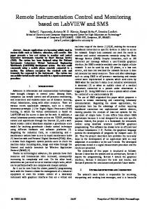
The choice of one of the above control criteria for each dam reservoir is intimately related to its location in the MAP system. In the Alqueva sub-system, the Alvito, Loureiro and Álamos reservoirs should be managed to minimize the Álamos PS energy costs. The Pisão reservoir and all the secondary reservoirs could work as low pass filters of canals flows. In the Pedrogão sub-system, all the reservoirs (S. Pedro and the secondary ones) should be managed according to energy cost criteria, since all PS deliver water directly to canals. The master controllers for the MAP dam reservoirs can be manually operated at the command center, due to the time (several days) required to change significantly the water surface elevation. On the other hand, the master controllers of the smaller reservoirs should be automatic, due to their number and faster dynamics (the water levels can take some hours to change significantly). Canals master controllers - The control criteria of the canal master controllers are to maintain downstream water levels (near the gates), in order to assure: - the correct functioning of the gates; - a stock volume to respond rapidly to varying flow demands at the offtakes. Canal dynamics is however rather complex and is usually described by a onedimensional space model based on the St. Venant equations (Cunge et al. 1980), that relate the flow rates Q( x, t ) and the water levels h( x, t ) along the canal (both function of time t and space x ). Therefore, the design of a controller that verifies the above mentioned control criterion faces some difficulties mainly due to the high time delay between the upstream flow and the downstream water level. Many different approaches have been studied in the recent years (Molina & Miles 1996): predictive control, optimal control, classical frequency domain control, etc. The typical behavior of the flow rates Q( x, t ) and the water levels h( x, t ) within a canal pool subject to a master-slave control are presented in Figure 5. The figure presents the numerical simulation results for the Pisão canal, considering the following conditions: initial steady flow of 20 m3/s, a +5 m3/s step change of the downstream flow (at t = 0 ) and a 3.59 m downstream reference water level. The simulations were done with an unsteady flow open-channel model that solves the St. Venant equations using a finite difference implicit scheme and considering a computational space step of 150 m. The master controller was based on a Smith Predictor with downstream flow feed-forward (Smith 1957). The step change of the downstream flow originates an upstream traveling wave and a decrease of the downstream water level. The master controller counteracts imposing an upstream flow temporary higher than the desired downstream flow, which originates a downstream traveling wave in order to compensate the volume withdrawn downstream. After the downstream traveling wave reaches the end of the canal pool, the downstream water level starts to increase until it reaches the
target value and the flow along the canal stabilizes around the downstream imposed value. Flow Rate
30
Q (m3/s)
28 26 24 22
12 10.5
20 3
9 7.5 2.5
6 4.5 Space (km)
2 1.5 Time (hour)
3
1
1.5
0.5 0
0
Flow Level
3.8 3.6
h (m)
3.4 3.2 3 2.8
12 10.5
2.6 2.4 3
9 7.5 2.5
2 Time (hour)
1.5
1
3 1.5 0.5
0
6 4.5 Space (km)
0
Figure 5. Flow Rates and Water Levels Along a Canal with Master-Slave Control MAP SCADA SYSTEM The MAP SCADA (Supervisory Control And Data Acquisition) system is composed of: - field units, to collect local data (water levels, flow rates, etc) and command local equipment (gates, pumps, etc); - a command center, to supervise/manage all the field units; - a communication system, to link the field units between them and to the command center.
Field Units There are seven different types of field units in the MAP system: canal gates, canal bifurcations, flow meters, canal outlets, dams, dam reservoir outlets and pumping stations (see Figure 2). The following equipments compose each field unit: automation/control, surveillance, power supply, communication, actuators and sensors. Usually, a shelter protects the most sensitive equipment from the weather conditions and vandalism. Automation/control - All field units will be equipped with a PLC, programmed to collect data from local equipments, perform control actions on the actuators and communicate with the command center. A data panel linked to the PLC will permit a human operator to access the field unit and command locally the actuators. Surveillance - For security reasons, the direct access to the field units should be restricted only to credentialed staff. Therefore, each field unit should have a specific access control system linked to the local PLC. In some field units (dams and pumping stations), its considered also important to install a set of fixed or remote operated CCTV cameras connected to a local video server that transmits automatically the images to the command center. This way the command center has a visual/acoustic contact with the field units, which can be helpful in different scenarios: intrusion, flood alarm, remote control of a machine (eg. gate, pump, etc). Power supply - All the field units will be generally supplied by the national electrical power network (EDP). Actuators - Along the MAP field units the following actuators will be installed: - gates, to control the flow/water levels along the canals and discharges in dam reservoirs; - valves, to control flow in pumping stations and regulate ecological flows in dams; - pumps, to pump water to higher levels. Sensors - A set of sensors will be needed on each field unit to evaluate the state of the system: - water level sensors, in the canals (up and downstream of each pool, to control the water levels and to compute gate discharged flow) and in the reservoirs (to evaluate the available water volumes); - flowmeters, at the canal and dam reservoir outlets and pumping stations to control the flows;
- vibrations sensors, in the pumping stations to protect the pumps against high vibrations. Command Center The command center will be located in the EDIA main building at Beja (see Figure 1), with the following functions: master control of the reservoirs, monitoring of all field units and to record and analyze all collected data. The command center will be constituted by a LAN (Fast Ethernet, TCP/IP) that connects the following machines (powered by a redundant UPS): - two redundant SCADA servers, to collect data from the PLCs and distribute it through the LAN; - two or more SCADA viewers, to allow human operators to view and interact with the data distributed by the servers and perform control actions; - one SCADA Internet-Gateway PC, to support a WEB page with on-line data from the servers, allowing this way access to the system via INTERNET; - one database PC (equipped with CD-ROM writer) for data recording; - one surveillance PC, for accessing the CCTV servers installed at the field units; - one central PC, to monitor the vibrations protection and condition monitoring systems installed at the pumping stations; - one LAN/WAN Management PC, for monitoring/management the MAP communication system; - one PC for remote setup and programming the field units equipment (eg. PLCs, UPSs, flowmeters, etc); - two or more printers, for reports and alarms registration; - a bridge, to connect the command center LAN to EDIA’s main LAN; - bridges/routers, to connect the command center LAN to the field units; - a video projection system, that permits the visualization in a big screen of all applications running on the computers linked to the LAN eg. SCADA diagrams, graphics, CCTV images, etc. Communication System The MAP communication system has to guarantee the communication between: - field units and the command center (FU/CC), so the command center can supervise and remote control the field units. Voice transmission between FU/CC is also important to permit a vocal contact between a CC operator and a local FU operator; - field units (FU/FU), so the downstream master controllers may transmit reference flows to the upstream slave controllers; - secondary reservoirs and field units (SR/FU), so the master controllers of the secondary reservoirs may specify on-line the desired demands to the water outlets slave controllers.
Since the secondary reservoirs are located generally at some distance (several km) from the water outlets and the frequency of communication is rather low (around 4 calls per day), the SR/FU communication may be done via PSTN or radio modem. Several different solutions for the FU/FU and FU/CC communication problems were studied, being the three most representative ones here presented: 1) Radio Trucking + ISDN, where all field units have a radio trucking modem connected to the PLCs to communicate between them. Each field unit communicates with the command center via the correspondent adduction unit (Dam or P S). Each Dam and PS has a copper Ethernet (TCP/IP) LAN (eg: 10BaseT) that connects all the local equipment (PLC, CCTV server, etc). A local router connects the LAN and an analog telephone to the command center via ISDN BRI. At the command center a modular bandwidth manager links an ISDN PRI to three analog telephones and to the CC LAN via an E1 router. 2) Ethernet + Leased Lines, where all the field units are linked by three separated single mode fiber optic Ethernet (TCP/IP) LANs (eg:10BaseFL): - one for the all the field units upstream Alvito Reservoir, with a total length around 70 km (50 km along the canals/siphons, 10 km underwater in the Álamos and Loureiro reservoirs and 8 km underwater in the Loureiro-Alvito Tunnel). - one for all field units downstream Alvito reservoir, with a total length 100 km installed along canals/siphons. - one for all field units of the Pedrogão sub-system, with a total length around 80 km installed along canals/siphons. The three LANs are connected to the command center in a star configuration. The first two LANs are connected through routers (at the Álamos PS and Alvito dam) via 2Mbps leased lines and the Pedrogão LAN is connected through a bridge via a 4 km fiber optic cable installed along a public road to Beja. All the LANs have ISDN routers installed at the end nodes, to provide communication backup in case of fiber optic failure. Each field unit has a copper Ethernet LAN (eg: 10BaseT) that connects all the local equipment (PLC, CCTV server, VOIP telephone, etc) to the fiber optic LANs through a media converter. Three VOIP telephones are connected to the CC LAN to permit vocal communication with the field units. 3) Ethernet + Microwave Radio links, where all the field units are linked by three separated single mode fiber optic Ethernet LANs as in the previous solution. The three LANs are connected with the command center in a ring
configuration using the following three redundant microwave radio links (working on a licensed frequency): Pisão Dam – Command Center (14 km), Alvito Dam – Loureiro/Alvito Tunnel (10 km) and Álamos PS – Pedrogão PS (26 km with a retransmiter). The above mentioned fiber optic link between Pedrogão LAN and the command center makes also part of the ring. Different kind of networks can be used to implement this ring like: Fast Ethernet, PDH, SDH, etc. A SDH ring may be interesting to explore with a telecommunication company. The Radio Trucking solution corresponds to a very simple and cheap communication system. However the implementation of this solution needs a field analysis of the local radio signal strength. According to previous tests done in the Alqueva area by a radio trucking company, the radio signal is generally sufficient although at some field units there is no signal at all. The Ethernet based communication systems represent a more modern solution, with several advantages over the radio trucking solution: high flexibility and reliability, good quality video transmission, redundancy and short time responses. The Ethernet + Microwave Links solution corresponds additionally to a totally private communication system with a very high redundancy. Economical Analysis The economical analysis presented, was based on the following assumptions: - a 60 year analysis period (first 30 years for start-up/building the system + 30 years full operation) with a 5% constant rate of interest; - all the costs presented include investment and maintenance costs and are reported to the year 2000; - the pumping costs were excluded from the electrical energy costs; - the life range of the equipments used. The costs relative to the Field Units, Command Center, Man Labour and Electrical Energy to run the system are estimated in 11130 (1000 Euros). The total costs of the SCADA system for each of the three different communication systems above mentioned are: Costs (1000 Euros) Common Communic. System Total
Radio Trucking + ISDN 11130 1400 12530
Ethernet + Leased Lines 11130 3800 14930
Ethernet + Microwave Links 11130 4300 15430
MAIN CONCLUSIONS Low-cost real-time instrumentation promises a revolution in improved water management in the water delivery open-channel systems. Today, real-time monitoring and control systems are within the cost range of almost all water user groups, including irrigators, canal companies and water districts. For the present case study, the main conclusions are: - since the estimate of the MAP total cost is around 1500 million Euros, the SCADA system represents approximately just 1% of the total costs; - although the Ethernet based SCADA systems are approximately 20% more expensive than the Radio Trucking solution, the technical advantages of the Ethernet solutions justify this difference. - SCADA system will permit to reduce conveyance losses and waste, to increase ability of meeting real-time demands by the water users and to reduce operation and labor costs. ACKNOWLEDGEMENTS The present study was supported by EDIA (Empresa de Desenvolvimento e InfraEstruturas do Alqueva, S.A.). The authors acknowledge to EDIA all the elements for the paper. The authors also acknowledge the contribution of Engineer Paulo Flores for the presented economical analysis results. REFERENCES Clemmens, A.J. (1987) - Delivery system schedules and required capacities. In Planning, operation, rehabilitation and automation of irrigation water delivery systems (ed. Zimbelman, D.D.), ASCE, New York, pp. 18-34. Cunge, J.A., Holly, F.M.Jr. e Verwey, A. (1980) – Practical Aspects of Computational River Hydraulics. Pitman Publishing Ltd., London. Molina, L.S. & Miles, J.P. (1996) – Control of an Irrigation Canal. Journal of Hydraulic Engineering (A.S.C.E.), 122(7):403-410. Smith, O.J.M. (1957) - Closer control of loops with deadtime. Chem. Engrg. Progress, 53:217-219.