Young's and Wensel's equations are the most basic theories of wettability related to ... modification of wettability with surface geometric texture which consists of ...
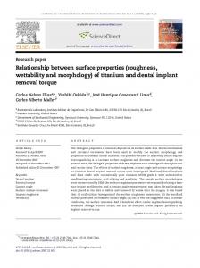
CONTROL OF WETTABILITY WITH SURFACE TEXTURING AND ITS APPLICATION Nobuyuki Moronuki, Kentaro Ryu and Arata Kaneko Tokyo Metropolitan University, 1-1 Minami-Ohsawa, Hachiohji, Tokyo 192-0397, JAPAN 1. Introduction Textured solid surface can provide various functions. Modification of wettability is the typical example, which is expected to provide hydrophobic or hydrophilic surface character for various situations. Young’s and Wensel’s equations are the most basic theories of wettability related to surface geometry. Extended explanation on periodically grooved surface was demonstrated both theoretically and experimentally by Oliver et al. [1]. Bico [2][3] also demonstrated the modification of wettability with surface geometric texture which consists of micro pillar array. Wettability can be also modified with coating of low surface-energy material such as PTFE [4] independently of the surface geometry. However, there is little approach that suggests a design methodology of surface texture to obtain intended wettability combining the effect of surface geometry and coating, especially considering the effect of gravity. The goal of this study is to establish such a design method. This paper aims to make clear the effect of patterned hydrophilic/hydrophobic pattern by coating on the wettability, including the effect of gravity. Then an application is demonstrated. 2. Definition of wettability Wettability is often referred as the contact angle of liquid droplet as the measure of characteristics for hydrophilic or hydrophobic surface. However, contact angle is not the only parameter to decide the wettability. CJ. Kim et al [4]. evaluated the flow resistance of microchannel with the sliding angle of water droplet on tilted surface. Sliding angle is the effective parameter for the evaluation of adhesive force between liquid and solid, which is sometimes important in practice. Actually, the relationship between the contact angle and sliding shown in Fig.1 has not been made clear. This, in this paper, both of the contact angle and sliding angle are employed for the evaluation of wettability.
Contact angle θa
Droplet
θb
Hydrophilic Sliding angle
Hydrophobic
Correspond ?
αb
αa
Fig.1 Background and problem Water drop
Receding Advancing angle angle θrec θadv Tilt α
Surface properties Wettability
Sliding angle
Fig.2 Experiments in this study 3. Experiments Figure 2 shows what done in the experiment. Firstly, Line-and-space pattern of hydrophilic and hydrophobic region was prepared on silicon substrate. Hydrophobic regions were produced by sputtering PTFE, and hydrophilic regions were produced by oxidation of silicon surface with SPM (H2SO4:H2O2=3:1) solution after the lithography and lift-off process. The thickness of the PTFE layer was less than 10nm and the original roughness of the substrate was less than 1nm. Thus, the effect of the surface geometry is
negligible and the effect of wettability only can be discussed. Hereafter, these patterns are referred as “PTFE/SiO2 texture”. The specifications of the pattern are summarized in Table 1. Secondary, the sliding angle and contact angle were measured using the setup shown in Fig.3. In order to evaluate the effect of droplet volume, a motorized micro-syringe was used and the shape of the droplet was analyzed using a CCD camera and capture board. The tilt angle was given by inclining the whole system. The conditions are shown in Table 2. Sliding direction was set parallel to the texture line. In addition to the sliding angle, the advancing angle and the receding angle were analyzed in order to investigate the detail of the phenomenon. Table 1 Properties of fabricated PTFE/SiO2 textures p Line width of PTFE and SiO 2 w Different ratio Constant ratio SiO 2 PTFE SiO2 No PTFE p-w No w p-w w 1 100 750 5 100 100 2 250 600 6 250 250 3 500 350 7 500 500 PTFE SiO 2 4 750 100 8 750 750 unit : µm
Syringe PC
Controller
M
Capture board CCD
Z-stage
M
Sample
Droplet
Light
Z-stage Tilt t
Microscope M
Table 2 Experimental conditions Liquid Pure water Droplet volume 20-70 [µl] Inclining speed 0.5-1.0 [deg/sec]
XY-stage Inclining unit
Stationary unit
Fig. 3 Setup for experiments
Sliding angle
deg.
Contact angle
Deg.
4. Results and discussions w=500µm p=1mm Figure 4 shows the relationship between θrec. θadv. droplet volume and sliding angle 120 (bottom) and the contact angle (top) of θadv. 100 sliding droplet on the PTFE/SiO2 PTFE 80 textures respectively. Sliding angles on 60 w=500µm PTFE and SiO2 without texture were θrec. 40 also shown. For PTFE, there is a 20 tendency that sliding angle decreased SiO 2 0 with the increase in droplet volume, 80 while that of SiO2 is almost constant. w P=850µm PTFE w=750µm 70 Droplets did not slide down when their w=500µm volume was less than 20µl because the 60 w=250µm strong surface force. When the volume 50 w=100µm PTFE SiO2 becomes larger, they slipped down due SiO2 40 to the effect of increased mass. 30 It was found from sliding angle point of view that the droplet adhered to PTFE 20 surface stronger than that of SiO2, 10 which seem to be the opposite in terms 0 of contact angle. As shown in the upper 10 20 30 40 50 60 70 80 figure in Fig.4, the advancing angle of Droplet Volume µl PTFE is larger than 90 degrees. Fig. 4 Sliding angle and contact angle vs. drop volume
However, it was found that the hysteresis of contact angle, θadv.-θrec., of PTFE is the largest in the case of PTFE. This fact suggests the work necessary to move the droplet on PTFE surface is larger and thus the sliding angle became large. It was also found that applying the texture the sliding angle can be set at desired value between PTFE and SiO2 surface depending on the area ratio of PTFE/SiO2 and droplet volume. In addition to the ratio of PTFE/SiO2 pattern, the width is also one of the design parameters. Figure 5 shows another results in which the pattern width was changed while keeping their ratio at constant. It was found that the sliding angle slightly decreased with the increase in the pattern width. These results indicate that both the area ratio of hydrophilic/hydrophobic region and the width of patterns should to be specified appropriately in the design of wettability. The profiles of sliding droplets were also observed from the normal direction of the surface using another microscope. It was found that the advancing line of the droplet was arc-shaped but the receding line was undulate exactly with the pitch of hydrophilic/hydrophobic line as shown in Fig.6. This was due to the difference of the wettability or drag force between PTFE and SiO2. The amplitude of this undulation varied depending on the line width. It is seen that the amplitude or drag height H increased almost linearly with the increase in PTFE line width. To elucidate this phenomenon, various force components should be taken into account such as volumetric force and surface force. This is, of course, one of the important future works. However, this type of wettability pattern can be applied for the self-assembling of fine particles.
60
p=2a PTFE SiO 2
40
PTFE W100 w=100 µm W250 w=250 µm W500 w=500 µm W750 w=750 m 系 µ列 SiO2系 列
30
1.0 1000
Receding line
0.8 800
w=100µm H
10 10
20 20
30 40 50 60 30 40 50 60 Droplet Volume V µl
70 70
80 80
Fig. 5 Effect of texture design on sliding angle
S lid in g
w=750µm
00
H
Water Water
0.2 200
10
Water
0.6 600 0.4 400
20 0
1.2 1200 mm
50
w
Drag height H
deg.
70
Sliding angle α
80
0 0
100 200 300 400 500 600 700 800 100 200 300 400 500 600 700 800 PTFE line width w µm
Fig.6 Profile of receding line of the droplet
5. Application of wettability pattern to continuous convective assembling of fine particles We applied the wettability pattern to so-called “continuous convective assembling of fine particles”. Figure 7 shows the principle. Drawing the patterned substrate from the suspension that include fine particles at specific angle, the particles gathered selectively on the hydrophilic regions due to the meniscus force between the particles while evaporation. In this process, the difference of contact angles between hydrophilic and hydrophobic region should be large as possible to gather them only on the hydrophilic region. Thus, in this experiment, octa-decyltrichlorosilane self-assembly monolayer (OTS-SAM) was used for hydrophobic material of which static contact angle was 105 degrees. The condition of this experiment corresponds to the extreme on the right side in Fig. 4 and 5 because the droplet volume is considered as infinite. Therefore the assembling process was affected by behavior of the receding line shown in Fig. 7. Figure 8 shows the photos of particles
Drawing direction
assembled on different hydrophilic region Drawing Evaporation width and pitch. It was found that the Particles particles were assembled with closest packing in monolayer on hydrophilic region. However, it is also seen that edge profile of Suspension assembled area is more continuous in the Hydrophilic area case of 70µm width while that of 35µm is Hydrophobic area discontinuous or no particles on the region. This is because receding undulation is larger for the texture of 70µm so that much more particles are supplied from hydrophobic region onto the hydrophilic region. These results are well explained by the former Suspension results and discussion. The assembled Fig.7 Continuous convective assembling of fine particles can be applied in various fields such particles as photonic crystal. w=35µm p=50µm
w=70µm p=100µm
Hydrophobic(OTS)
5µ m Fig.8 Assembled fine particles on OTS/SiO2 textures of different width and pitch 6. Conclusions For the purpose of establishing the design methodology of surface texture to obtain intended wettability, influences of droplet volume and hydrophilic/hydrophobic pattern on sliding angle were investigated. The relationship among them indicated the possibility of controlling wettability by designing texture appropriately. Continuous convective assembling of fine particles was carried out as the application of droplet sliding on hydrophilic/hydrophobic alternate lined texture. Influences of line width and pitch were shown to have relation with assembling rate of particles in intended place on substrate. References [1] Oliver J. F. et al, The Apparent Contact Angle of Liquid on Finely-Grooved Solid Surface, Journal of Adhesion, 8 (1977), 223-234. [2] Bico J., Marzolin C. and Quere D., Pearl drops, Europhysics letters, 47-2 (1999), 220-226. [3] Bico J., Thiele U. and Quere D., Wetting of textured surfaces, Colloids and Surfaces, A: Physicochemical and Engineering Aspects 206 (2002), 41-46. [4] Kim J., Kim CJ., Nanostructured Surfaces for Dramatic Reduction of Flow Resistance in Droplet-Based Microfluidics, MEMS Conference, IEEE, (2002) ,479-482.